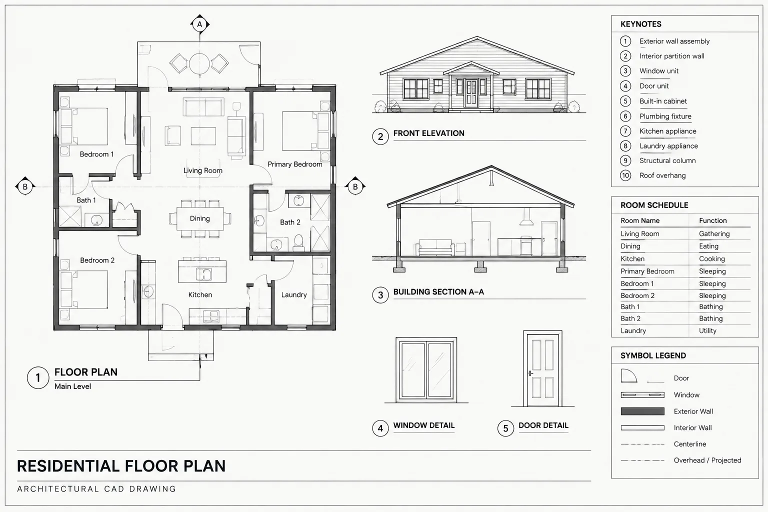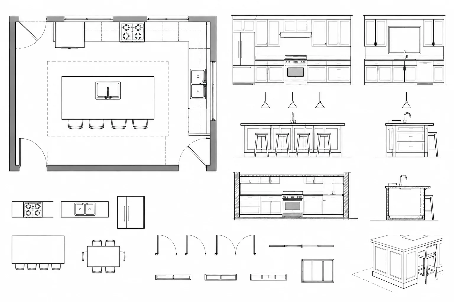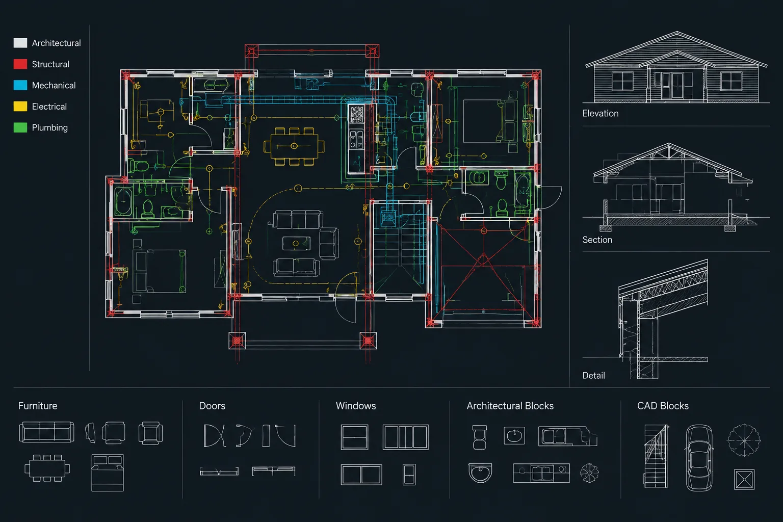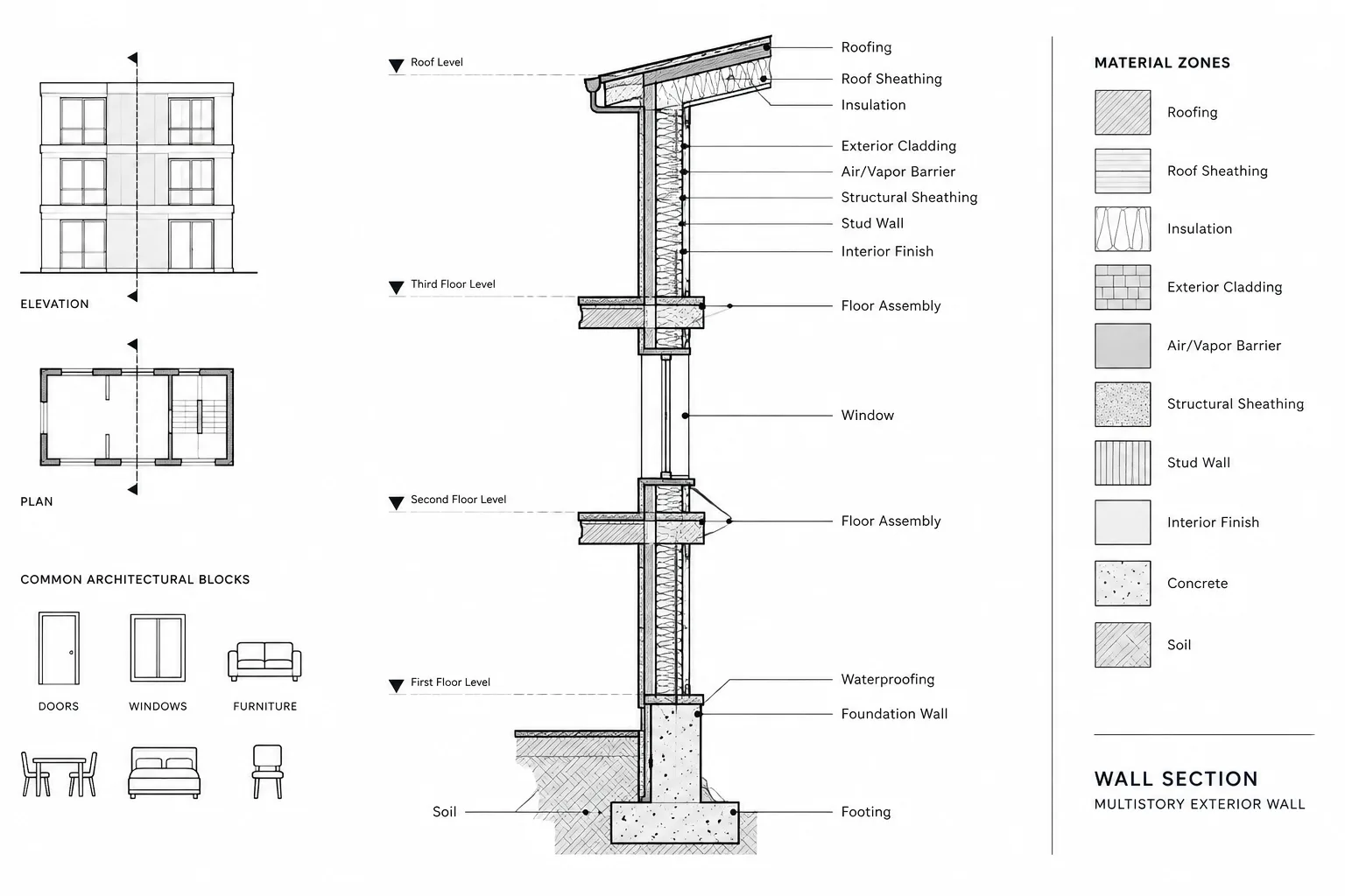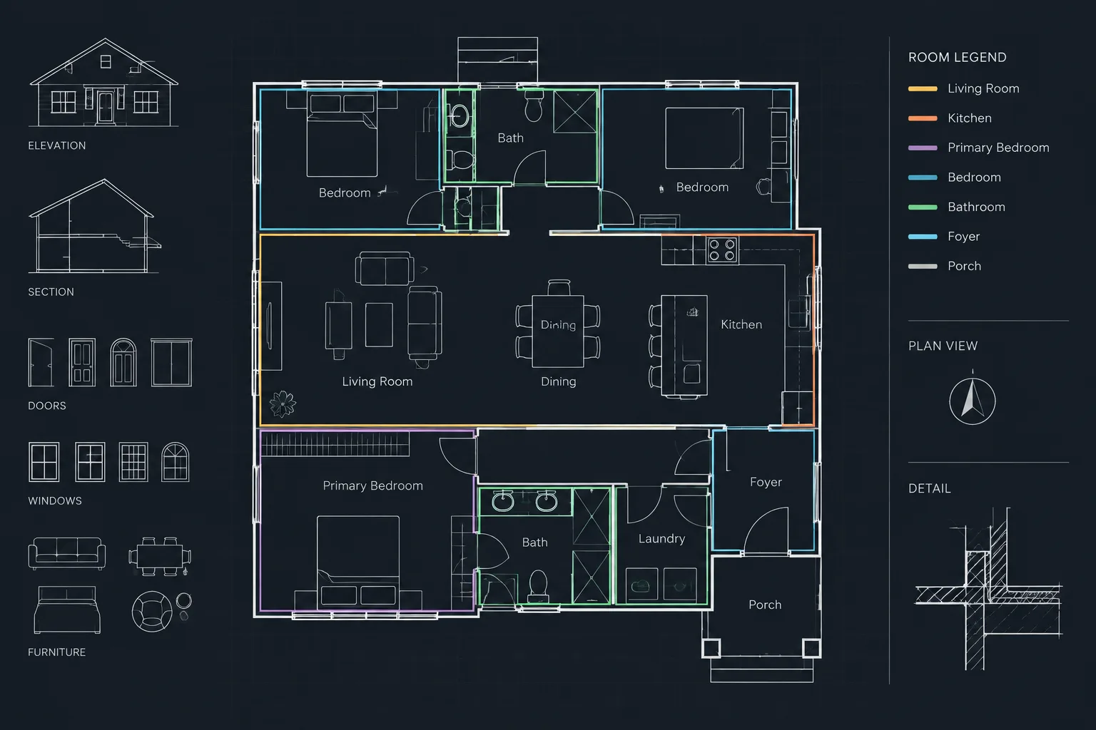
Accurate room areas depend on more than selecting a command and reading a value. The boundary must represent the project’s agreed measurement method, remain coordinated with the floor plan, and support a result that another team member can verify.
This guide explains a practical workflow for room area calculations in AutoCAD, from defining the measurement reference and creating closed polylines to linking labels, reviewing exclusions, and checking revised drawings. The goal is not merely to obtain an area value, but to create an auditable relationship between the plan geometry, the calculation boundary, and the reported information.
Room area calculations in AutoCAD can appear straightforward: draw a boundary, read its area, and place a label. In practice, unreliable results often come from inconsistent measuring rules, open polylines, duplicate geometry, incorrect drawing units, or boundaries that no longer match the floor plan.
A dependable workflow treats each area boundary as controlled drawing data rather than temporary construction geometry. The drafter must first define what is being measured, then create clean closed objects, connect those objects to labels or schedules, and verify the results whenever the plan changes.
Define the measurement purpose before drawing boundaries
There is no single room-area boundary that serves every purpose. A design team may need areas for space planning, finish quantities, programming, leasing, facility management, or regulatory documentation. Each use can apply different rules at walls, columns, shafts, recesses, and shared partitions.
Before tracing rooms, document the project’s measurement convention. Questions to resolve include:
- Does the boundary follow the finished wall face, partition centerline, or another defined reference?
- Are columns, shafts, built-in cabinets, and wall projections included or excluded?
- Are open-plan zones measured separately even when no physical wall divides them?
- How are double-height spaces, stairs, voids, and floor openings handled?
- Which source controls when architectural, leasing, and consultant backgrounds differ?
Do not assume that a CAD area automatically represents a code, leasing, or contractual area. Those classifications depend on the governing method selected for the project. Record the method in project instructions or drawing notes instead of relying on team memory.
Confirm drawing units and geometry scale
An area value is only meaningful when the source geometry uses the intended units. Before creating boundaries, check a known building element and confirm that the measured distance agrees with the project’s dimensional system. A file inserted or referenced at the wrong scale can produce plausible-looking plans with unusable area totals.
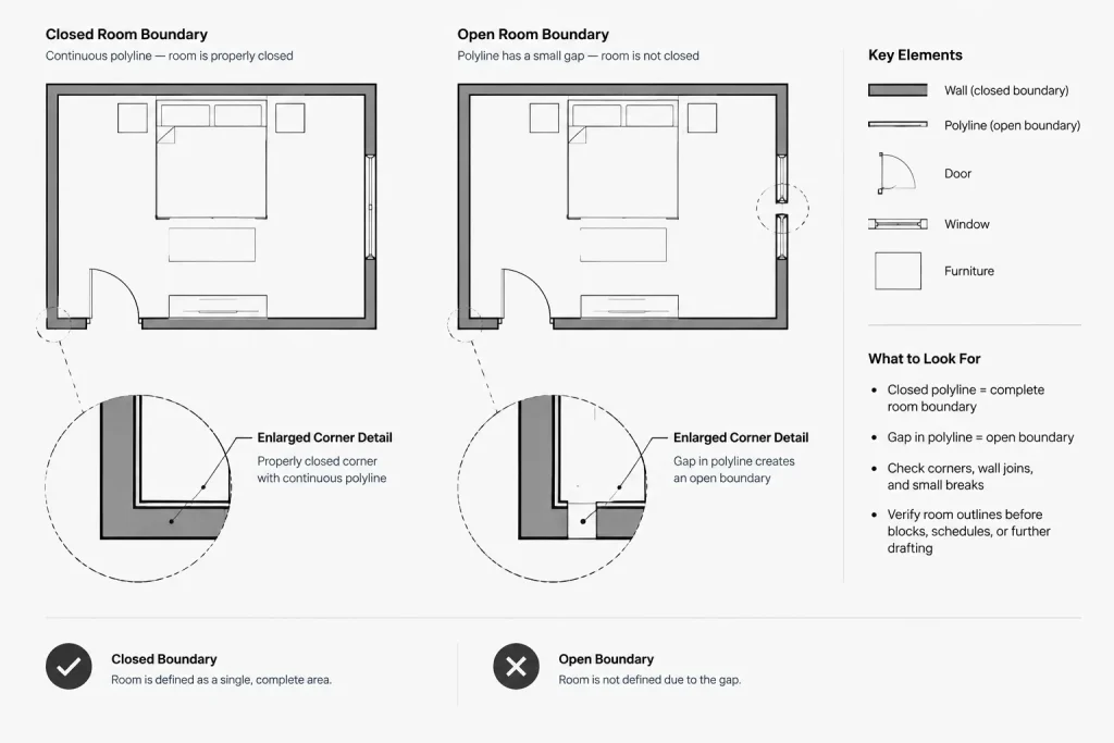
Also confirm whether the working file represents the building at full size in model space. Sheet viewport scale should control printed presentation; it should not be used to compensate for incorrectly scaled model geometry.
Area formatting requires its own decision. The drawing may store geometry in one base unit while labels display a larger square unit. Establish the conversion and rounding method once, then apply it consistently. Avoid manually converting some rooms while using automated values for others.
Create a dedicated area-boundary layer
Place room boundaries on a clearly named, non-plotting layer reserved for area calculations. Keeping them separate from walls, room outlines, finish hatches, and annotation makes them easier to audit and protects the architectural linework from accidental edits.
A useful area layer should be easy to identify on screen without dominating the plan. Teams can also use separate layers when distinct boundary methods must coexist, such as programming areas and finish areas. Layer names should communicate the measurement purpose rather than using a vague label such as miscellaneous or calculation.
Build clean closed polylines
A closed polyline is generally the most manageable source object for a room calculation. It can be selected, edited, inspected in Properties, and associated with an area label. A collection of loose lines may visually enclose a room but does not provide the same dependable object-level control.
Trace deliberately
For simple spaces, draw the polyline directly along the approved measurement reference. Use object snaps to connect corners accurately, but avoid snapping to unrelated furniture, hatches, ceiling elements, or consultant geometry.
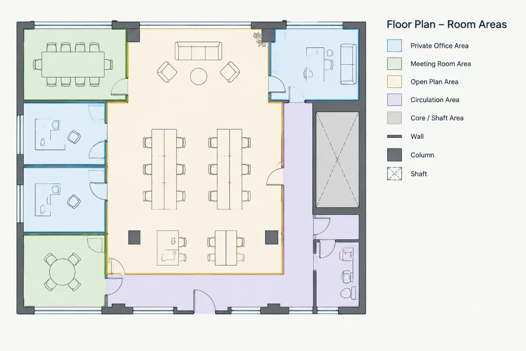
The BOUNDARY command can create a polyline from an enclosed region, but the result should always be reviewed. Dense plans may contain tiny gaps, overlapping wall lines, door graphics, or hidden objects that cause the generated boundary to leak into adjacent spaces or follow the wrong edge.
Close the object properly
A polyline whose last vertex visually meets its first vertex is not necessarily flagged as closed. Check the object’s Closed property or use an appropriate polyline-editing operation. This distinction matters because later edits can expose a gap that was previously difficult to see.
Handle internal exclusions intentionally
A room with a shaft, opening, or excluded zone may require more than one object. One approach is to maintain an outer boundary and separate inner boundaries, then calculate the difference. Another is to construct a single outline that traces around the exclusion. Choose a method the team can understand and audit.
Do not use a hatch as the only record of the area definition. Hatches can help visualize included regions, but their associative behavior and island detection can change when surrounding geometry is edited. Retain explicit boundary objects as the calculation source.
Choose how area values will be reported
| Method | Best use | Main caution |
|---|---|---|
| Properties palette | Quick inspection and spot checks | The value is not automatically documented on the drawing |
| AREA command | Independent verification or temporary calculations | Point-by-point measurement can differ from the stored boundary |
| Object-linked field | Labels that should follow a specific boundary object | The display must be updated and checked after geometry changes |
| Manual text | Exceptional cases with controlled external calculations | The text can become disconnected from the current plan |
| Extracted object data | Schedules and broader area audits | Layer discipline and object selection must be consistent |
For a small plan, inspecting the polyline area in Properties may be sufficient during design. For issued room labels or schedules, object-linked fields can reduce transcription errors. A field can reference the area property of a selected polyline and apply formatting, but it should not be treated as self-verifying. Changes may require field updates or drawing regeneration before the displayed text reflects the current object.
When labels are manually entered, establish a review procedure that compares each label with its current source boundary. Manual values should never be copied from an earlier plan without checking the revised geometry.
Keep boundaries coordinated with plan revisions
Area objects often become outdated because they look like secondary graphics. A wall moves, but the non-plotting boundary remains in its previous location. The label may still display a valid area for the wrong shape.
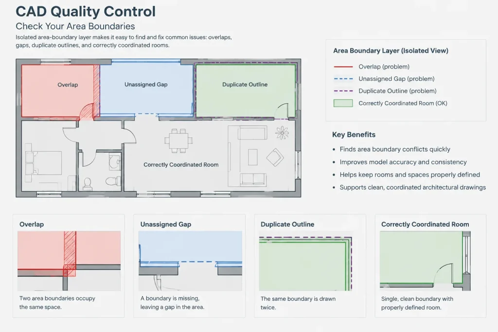
Include area boundaries in the normal plan-editing process. When partitions, columns, shafts, or fixed casework change, review the affected rooms before considering the revision complete. Isolate the area layer periodically and compare its edges against the architectural plan.
Object-linked labels help with numeric updates only when the referenced polyline itself has been corrected. Automation cannot identify that a boundary is geometrically obsolete.
Quality-control checks for room areas
Inspect individual boundaries
- Confirm that every measured room has one clearly identifiable source boundary.
- Check that each primary boundary is closed and free of self-intersections.
- Look for duplicate polylines stacked in the same location.
- Verify curved segments and angled walls rather than approximating them unintentionally.
- Confirm that exclusions are handled according to the selected measurement method.
Review the plan as a system
- Isolate all area layers and look for gaps, overlaps, and unassigned spaces.
- Compare adjacent boundaries at shared partitions to confirm that the chosen reference is consistent.
- Check room names and numbers against the area labels or schedule.
- Review unusually large or small values rather than assuming they are correct.
- Compare subtotals with an independently measured overall zone where that comparison is appropriate.
Check displayed values
- Update fields before plotting or exporting the drawing.
- Confirm the intended square-unit conversion and rounding convention.
- Make sure labels have not lost their object references.
- Check that copied labels do not still point to boundaries in other rooms.
- Review the final PDF, because a correct model-space value is not useful if the label is clipped or unreadable on the sheet.
A practical room-area workflow
A controlled production sequence can be summarized as follows:
- Confirm the project’s measurement purpose and written boundary rules.
- Verify the drawing units and model scale against known geometry.
- Create dedicated non-plotting layers for each required area category.
- Draw or generate closed polylines and inspect their paths.
- Add linked labels or record verified values using the project’s chosen method.
- Coordinate room identifiers between plans, tags, and schedules.
- Isolate the boundaries and review gaps, overlaps, exclusions, and duplicate objects.
- Update calculations after plan revisions and before each drawing issue.
- Perform a final visual and numeric check in both the DWG file and plotted output.
Common mistakes to avoid
Do not assume that a visible enclosure is a valid closed object. Avoid tracing over finish hatches without knowing which edge controls the measurement. Do not mix wall-centerline and finished-face methods within the same area category. Refrain from exploding useful boundary polylines into loose segments, and do not move room labels without confirming which object they reference.
Most importantly, do not present calculated values as universally defined areas. CAD can calculate the geometry accurately, but it cannot decide which measurement convention applies. Reliable room area calculations in AutoCAD depend on combining clean geometry with a documented project method and repeatable quality control.
Make the area boundary part of the drawing record
A reliable area calculation should be traceable. A reviewer should be able to identify the controlling polyline, understand why it follows a particular wall reference, confirm how exclusions were treated, and compare the reported value with the current floor plan.
This traceability becomes especially important when several area categories appear in one project. Programming, finish, leasing, and other calculations may use different boundaries even when they describe the same room. Separate layers, clear naming, and documented measurement rules help prevent one category from being mistaken for another.
Prepare room areas for team review
Before handing off the drawing, isolate the calculation layers and inspect the boundary network without the distraction of annotation, furniture, or hatch patterns. Then restore the complete plan and confirm that each boundary still aligns with its intended architectural reference.
- Identify the source boundary associated with every reported room area.
- Confirm that linked labels reference the intended objects.
- Flag any values produced outside the drawing so reviewers know they require separate coordination.
- Record unresolved assumptions involving wall references, openings, shafts, or open-plan zones.
- Check the plotted sheet as well as the model geometry.
A clean polyline is only one part of quality control. The final result must also use the correct measurement convention, remain synchronized with revisions, and communicate clearly in labels or schedules.
Frequently asked questions
Why can a room look enclosed but fail to produce a dependable area?
Visible wall lines may contain small gaps, overlaps, duplicate segments, or geometry at different elevations. The apparent enclosure may also include door graphics, hatches, or unrelated objects. Create and inspect a dedicated closed boundary rather than relying only on the visual appearance of the plan.
Should room areas be measured to the wall face or wall centerline?
The correct reference depends on the project’s stated measurement purpose and governing method. Select the convention before tracing boundaries, document it, and apply it consistently across the relevant area category.
Are object-linked fields automatically accurate after a plan revision?
No. A field can report the property of its referenced object, but it cannot determine whether that object still follows the revised walls. Correct the boundary first, then update and review the displayed field.
Can a hatch be used as the room-area source?
A hatch may help visualize an included region, but it should not be the only record of the measurement boundary. Explicit polylines are generally easier to isolate, inspect, edit, and audit when the plan changes.
How should shafts or other excluded zones be handled?
Use a documented method that clearly distinguishes the outer room boundary from internal exclusions. The chosen geometry should make the subtraction understandable to another drafter or reviewer without relying on an undocumented manual adjustment.
Why might a correct model-space area still be reported incorrectly?
The source geometry may be correct while the label uses an unintended unit conversion, rounding rule, stale field value, broken reference, or manually entered number. Review both the boundary and the displayed output.