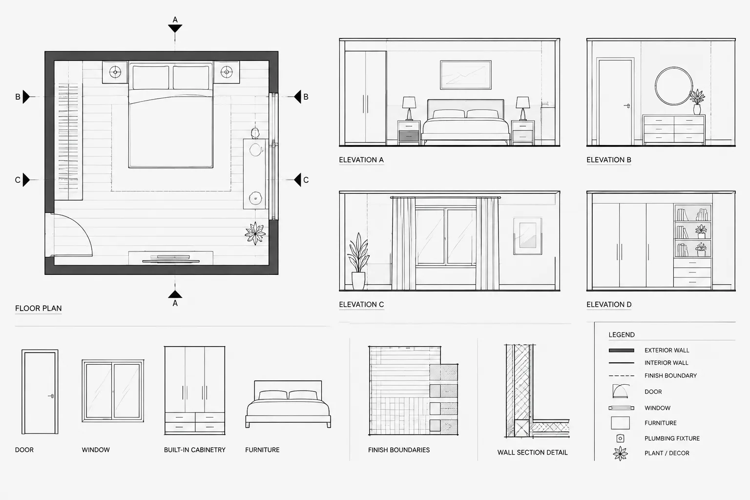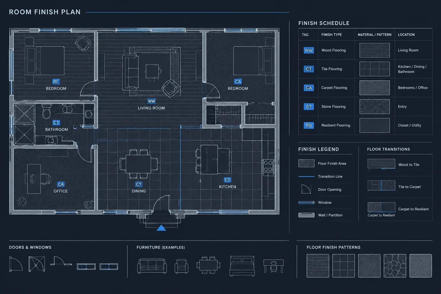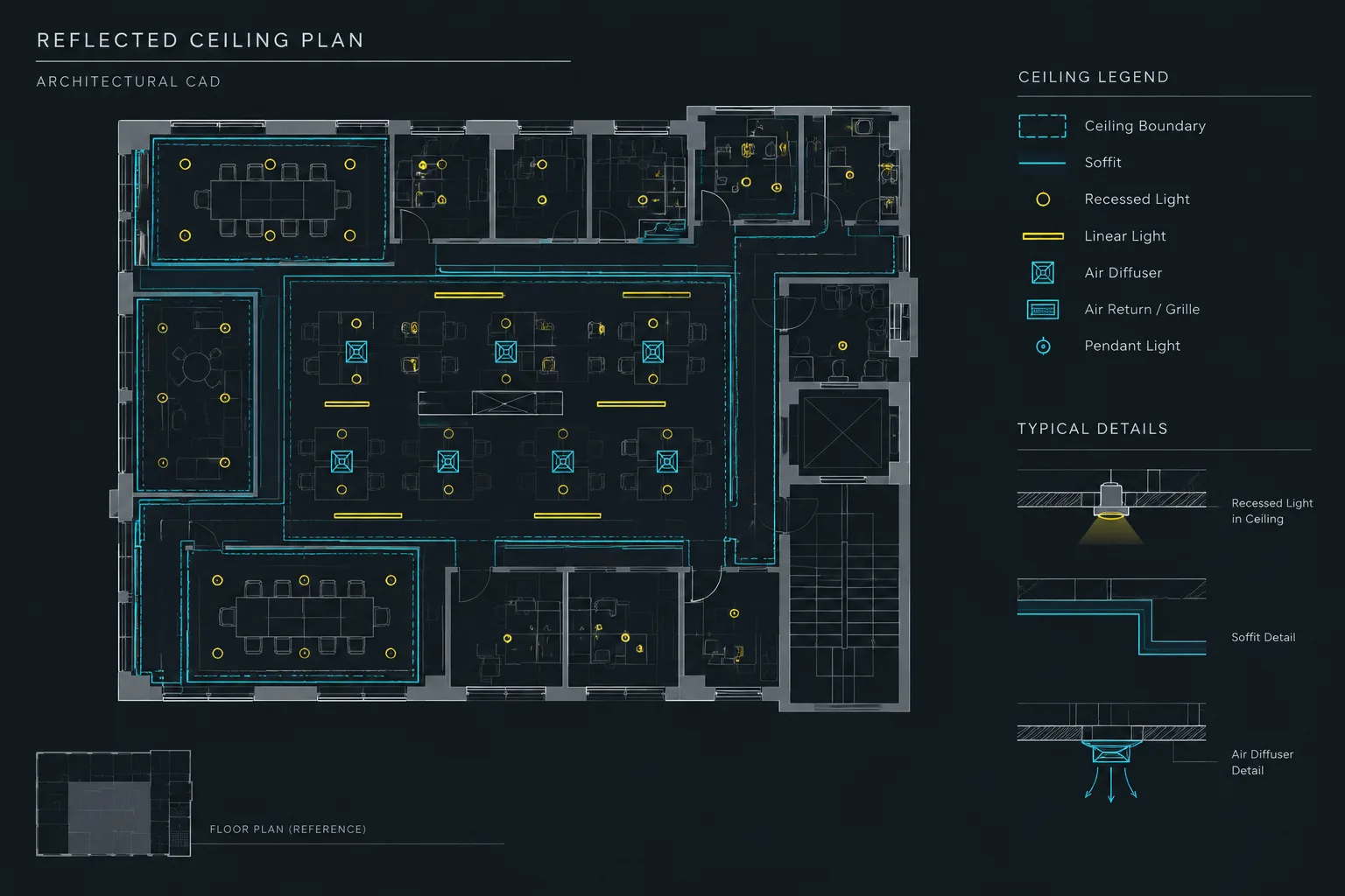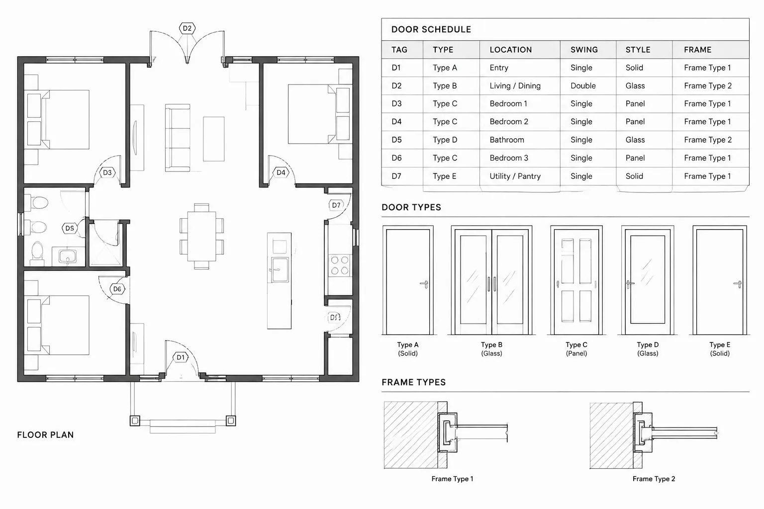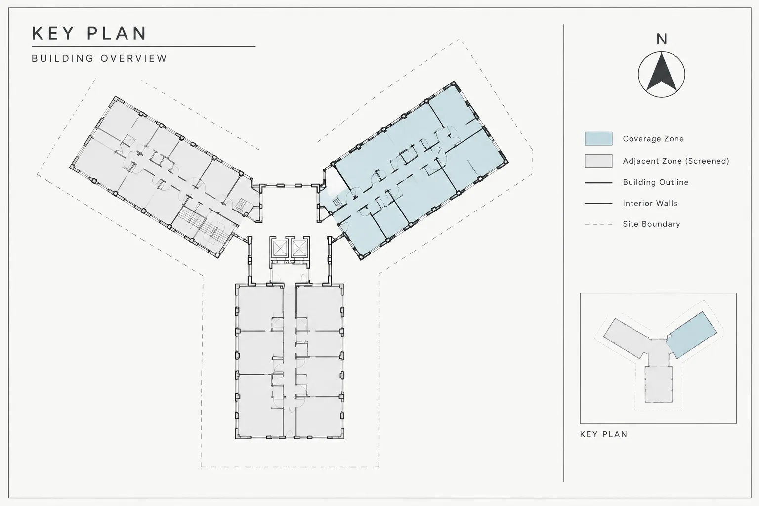
Architectural key plans in CAD support drawing-set navigation by connecting each partial plan to the larger project. Their value depends less on graphic complexity than on coordinated coverage, recognizable geometry, consistent naming, and reliable plotting.
This guide explains how to establish a controlled source, simplify plan geometry, represent sheet extents, coordinate orientation, and review repeated key plans as the drawing set changes. Use the workflow as a drafting and quality-control framework, then adapt the graphic conventions to the project and office standards.
A key plan is a small orientation diagram that shows where a drawing view fits within a larger building, floor, or site. It is especially useful when a project is divided into several plan sheets, wings, zones, phases, or buildings. A well-made architectural CAD key plan helps readers understand sheet coverage without searching through the entire drawing set.
Although a key plan is usually simple, it must remain coordinated with the plans it represents. Outdated boundaries, inconsistent area names, and mirrored orientation can make the diagram misleading. The best workflow treats the key plan as controlled project information rather than decorative sheet content.
What an Architectural Key Plan Should Communicate
The key plan should answer a few immediate questions: Which part of the project is shown on this sheet? How is that area oriented? What are the neighboring areas? Which floor, building, or phase is represented?
Depending on the project, a key plan may include:
- A simplified building or site outline
- A highlighted sheet coverage area
- Adjacent coverage areas or divisions
- Area, wing, building, or phase labels
- A north arrow or another approved orientation reference
- Match lines or zone boundaries when they help explain the split
- A floor or level identifier
- A small title describing what the diagram represents
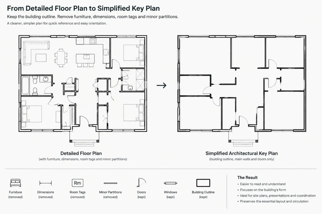
Not every item belongs in every key plan. The diagram should contain only the information needed to locate the view. Doors, furniture, dimensions, room tags, finish patterns, and minor wall offsets usually create unnecessary visual noise.
Key Plan, Overall Plan, and Vicinity Map Are Not the Same
| Graphic | Primary purpose | Typical content |
|---|---|---|
| Key plan | Locates a drawing area within the project | Simplified project outline, coverage highlight, area labels, orientation |
| Overall plan | Shows the project as a coordinated plan view | Architectural geometry, major references, annotations, and broader design information |
| Vicinity map | Locates the project within its surrounding area | Nearby roads, blocks, landmarks, or other geographic context |
| Site plan | Documents the arrangement of buildings and exterior work | Property context, access, paving, landscape, utilities, grading, or other project-specific information |
A reduced overall floor plan does not automatically become a good key plan. If the reduction makes walls and annotations merge into a dark mass, create a separate simplified diagram instead.
Choose a Reliable Source for the Diagram
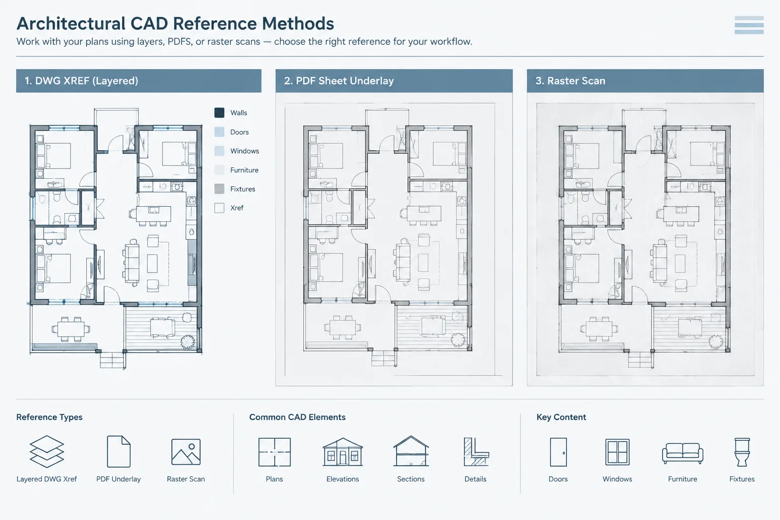
Begin with coordinated project geometry. The source might be an architectural base plan, a controlled external reference, or a dedicated diagram file derived from the current plan. Avoid tracing a plotted sheet when reliable DWG geometry is available, because the traced version can become disconnected from later design changes.
There are several practical ways to manage the source:
- Dedicated key-plan file: Useful when many sheets share the same diagram and area structure.
- Referenced project base: Keeps the underlying outline connected to a coordinated drawing, provided unnecessary layers can be controlled.
- Controlled block: Effective for a compact diagram used repeatedly within one drawing set.
- Sheet-specific linework: Acceptable for a limited project, but it creates more opportunities for separate copies to drift apart.
The right method depends on project size, team structure, and office standards. Whichever method is selected, identify one source as the maintained master rather than allowing every sheet to contain an independently edited version.
Simplify the Building Without Changing Its Meaning
Copying every plan element into the key plan produces a fragile and cluttered graphic. Reduce the source to recognizable exterior outlines, major courtyards, connecting links, and meaningful area divisions. Interior partitions should appear only when they are essential to understanding the building organization.
Simplification should not distort the project. Preserve the relative position of wings, major offsets, and circulation links. A reader familiar with the overall plan should be able to recognize the key plan immediately.
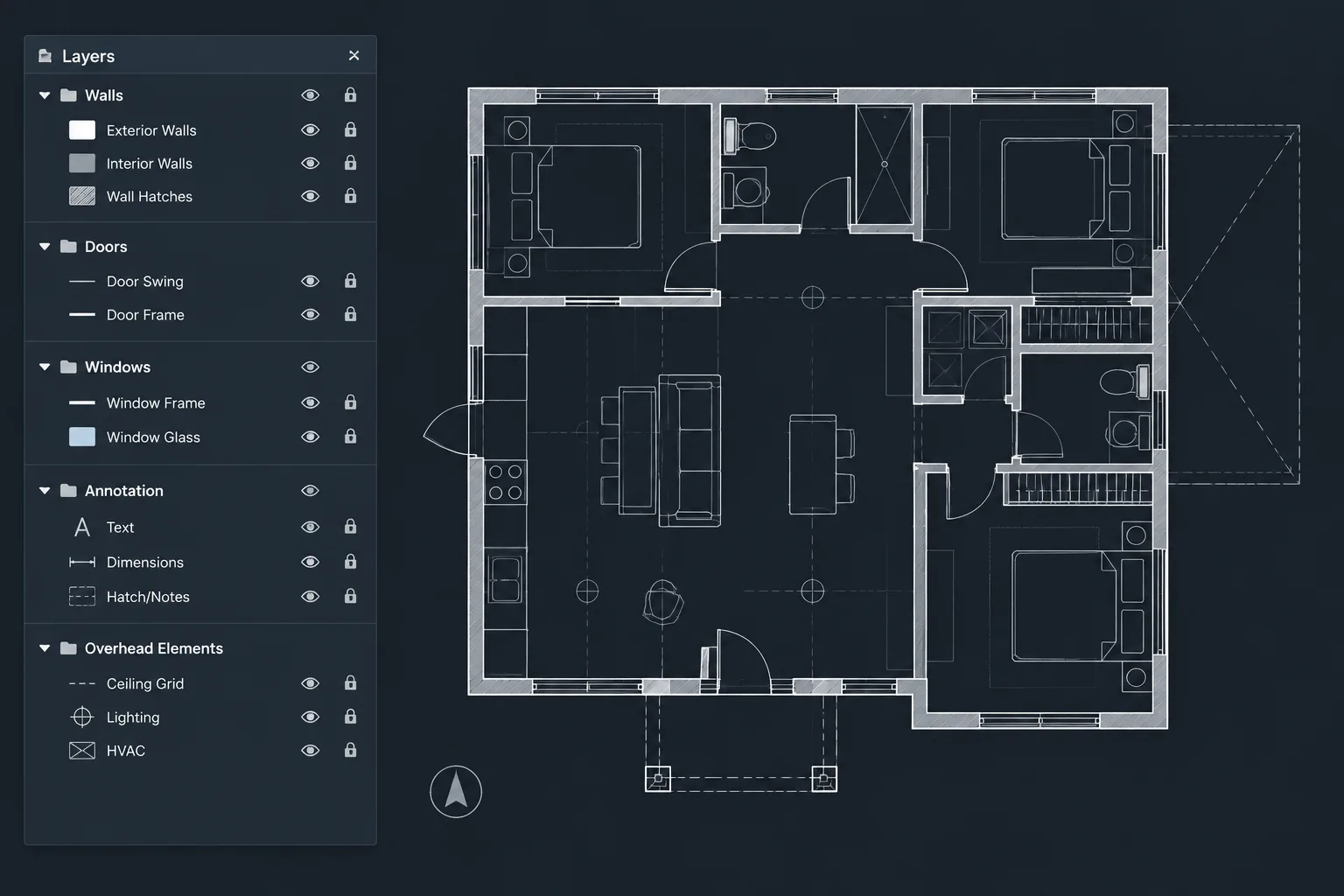
Use a Small, Purpose-Built Layer Set
Separate the diagram into functional layers so its display can be adjusted without editing objects individually. A typical organization may distinguish:
- Background building outlines
- Highlighted coverage
- Area boundaries or match lines
- Labels
- Orientation symbols
- Optional screened context
Use project-approved layer names and plotting conventions. Avoid assigning appearance through random object overrides when layer-based control can provide a more predictable result.
Define Sheet Coverage Before Applying Graphics
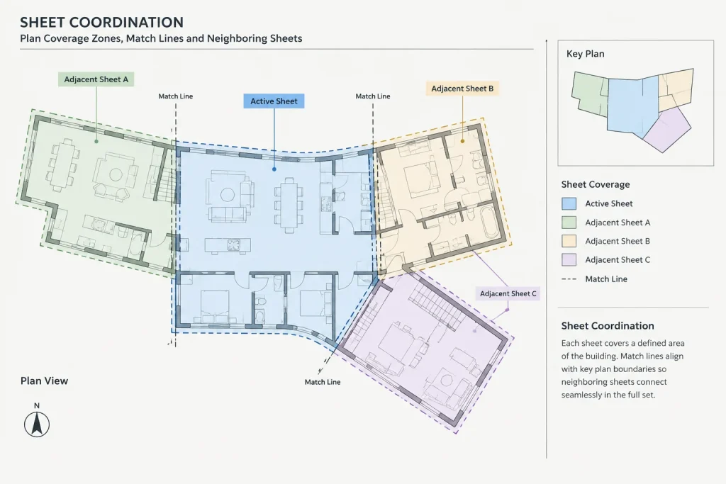
The highlighted region must represent the actual extent of the plan view on the sheet. Do not assume that a wing name or structural grid range matches the viewport boundary. Compare the key plan directly with the viewport, crop, match lines, and adjacent sheets.
Coverage can be shown with a solid outline, screened fill, hatch, heavier boundary, or another consistent graphic device. The highlighted area should remain legible in both color review files and monochrome plots. If color is used, test whether the distinction survives the project’s final plotting method.
For irregular sheet divisions, use a closed polyline or similarly controlled boundary rather than a loose collection of segments. Closed boundaries are easier to revise and reduce the chance of gaps in hatches or fills.
Keep Orientation Consistent with the Drawing View
Orientation errors are particularly confusing because a diagram can look plausible while pointing the reader in the wrong direction. Decide whether the key plan follows project north, true north, or the orientation of the main plan viewport. The choice should match the project’s drawing convention and be applied consistently.
If different sheets rotate plan views for readability, determine whether the key plan rotates with each view or remains fixed throughout the set. Both approaches can work, but the graphic must make the relationship unambiguous. An orientation symbol should not be copied from another sheet without confirming that it still points correctly.
Build a Reusable Key Plan Assembly
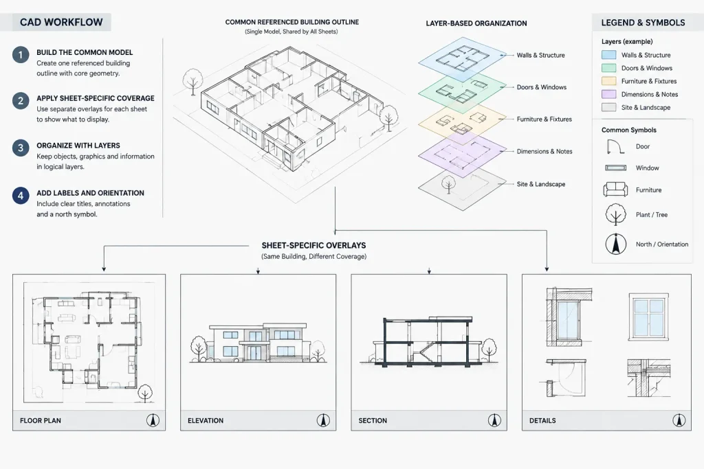
A reusable assembly can include the base outline, area divisions, labels, orientation symbol, and a controlled method for highlighting coverage. Depending on the project, this may be managed as an external reference, a block, or a combination of referenced geometry and sheet-specific overlays.
Keep sheet-specific highlighting separate from the common background when practical. This allows the master outline to update across the set while each sheet retains its own coverage indication. If the entire diagram is placed in a block, establish a logical insertion point and confirm that labels, hatches, and linework behave correctly after insertion.
Model Space or Paper Space?
A key plan can be placed in model space and viewed through a viewport, or assembled directly in paper space. A model-space source is helpful when the diagram must maintain a controlled relationship to project geometry. Paper-space placement can simplify sheet composition when the graphic is purely diagrammatic.
A hybrid method is also common: maintain the project outline in a referenced model-space file, then add sheet-specific titles or highlights in the sheet drawing. The important issue is not the location alone, but whether the source, scale, plotting behavior, and update responsibility are clear.
Coordinate Labels and Area Names
Area labels should use the same terminology found in sheet titles, match-line references, drawing indexes, and plan callouts. Avoid informal abbreviations that appear nowhere else in the set. If a building area changes name during design, search for the old name across all related key plans and sheet annotations.
Text must remain readable at the final plotted size. Do not rely on zooming within a PDF to rescue labels that are too small or crowded. Review the diagram on a test plot or at an equivalent on-screen print preview.
Quality-Control Checklist
- Confirm that the building outline reflects the current coordinated plan.
- Verify that the highlighted region matches the sheet’s actual view coverage.
- Compare match lines and neighboring areas with adjacent sheets.
- Check the floor, building, wing, and phase labels.
- Verify the orientation symbol against the plan viewport.
- Confirm that fills and screening remain distinguishable in the final plot style.
- Look for clipped labels, broken boundaries, missing references, and hatch display problems.
- Check that repeated key plans use the same graphic hierarchy and terminology.
- Remove unnecessary plan detail that reduces clarity.
- Review the diagram after any major plan split, rotation, or sheet renaming.
Treat the Key Plan as Part of Drawing Navigation
A key plan works best when it is coordinated with match lines, view titles, sheet references, drawing indexes, and area names. Together, these elements form a navigation system for the drawing set. If one element uses different terminology or coverage logic, readers must interpret the discrepancy themselves.
The goal is not to create a miniature floor plan. It is to provide a fast, dependable answer to where the reader is within the project. A simplified master source, clearly defined coverage, consistent orientation, and routine plot review will make the architectural CAD key plan useful throughout design, coordination, and drawing issue workflows.
A Practical Coordination Sequence
Key-plan production is easier to manage when decisions are made in a deliberate order. Confirm the maintained project source before simplifying geometry. Establish the drawing-set divisions and actual viewport coverage before creating highlights. Resolve orientation before placing symbols and labels. Apply graphic hierarchy only after these relationships are stable.
This sequence helps prevent a common drafting problem: polishing a diagram before confirming that it represents the correct area. A visually consistent key plan can still be wrong if its boundary, label, or orientation was derived from an earlier sheet arrangement.
Assign Ownership and Revision Triggers
The project team should understand who maintains the common outline and who verifies sheet-specific coverage. Clear ownership reduces the risk of several drafters updating separate copies without coordinating the master diagram.
Key plans should be reviewed whenever changes affect drawing navigation. Relevant triggers include revised plan splits, renamed areas, rotated viewports, altered match lines, relocated sheet views, and changes to the building or site configuration. Treating these events as coordination triggers is more dependable than waiting for a final drawing review.
Separate Shared Information from Sheet-Specific Information
The project outline, common area divisions, and established names usually belong to the shared key-plan source. Coverage highlighting, sheet-specific emphasis, and certain view notes may need to remain within the individual sheet file. Keeping these responsibilities distinct makes updates easier to trace.
When repeated diagrams disagree, compare their sources rather than correcting only the visible symptom. An incorrect highlight may result from an outdated overlay, while an incorrect outline may indicate that the common source has not been refreshed.
Review the Navigation Chain
A key plan should not be checked in isolation. Follow the reader’s path from the drawing index to the sheet title, view title, key plan, match line, and adjoining-sheet reference. Terminology and coverage logic should remain consistent throughout that chain.
Plot review is also essential. Confirm that background geometry remains visible without competing with the highlighted area, that boundaries do not disappear under the plot style, and that labels remain readable at the intended output. If the diagram works only when enlarged on screen, its sheet presentation needs further refinement.
Common Problems and Corrective Actions
- The highlight does not match the viewport: Compare the closed coverage boundary with the actual crop, match lines, and adjacent views rather than relying on an area name.
- The diagram appears mirrored or rotated: Verify the source orientation, viewport rotation, and orientation symbol as a coordinated group.
- The key plan is too dense: Remove annotations and interior geometry that do not help readers identify the building area.
- Repeated sheets show different outlines: Trace each instance back to its source and replace uncontrolled copies with the maintained assembly.
- The fill disappears or becomes too dominant: Review layer properties, hatch behavior, screening, and the final plot method together.
- Area names conflict: Compare the labels with sheet titles, indexes, match-line references, and current project terminology.
Before issue, review the key plan as navigation information rather than as an isolated CAD graphic. The final question is whether a reader can identify the displayed area, understand its relationship to neighboring areas, and move through the drawing set without resolving avoidable inconsistencies.
Frequently Asked Questions
What is an architectural key plan in CAD?
It is a simplified orientation diagram showing where a drawing view or sheet coverage area belongs within a larger floor, building, site, phase, or project arrangement.
Should a key plan be copied from the full floor plan?
A coordinated plan can provide the source geometry, but the resulting diagram should be simplified. Retain recognizable outlines and meaningful divisions while removing details that do not support orientation.
Should every sheet have a separately edited key plan?
Independent copies are difficult to coordinate. A maintained common source with controlled sheet-specific highlighting generally makes revisions easier to manage and review.
Can a key plan be placed in paper space?
Yes. Paper-space placement can work for a diagrammatic graphic, while model-space or referenced geometry may be preferable when the outline must remain connected to project geometry. The chosen method should make source control and plotting behavior clear.
How should coverage be highlighted?
Use a consistent graphic method that remains distinguishable under the final plot conditions. The boundary should correspond to the actual drawing view rather than an assumed wing, grid range, or area label.
When should a key plan be updated?
Review it after changes to plan geometry, sheet divisions, viewport orientation, match lines, area names, phases, or drawing references. Any change that affects navigation can make an existing diagram outdated.
Why does a key plan look clear on screen but fail in print?
Screen color, zoom, and display settings can conceal weak lineweight contrast, crowded labels, or ineffective screening. Evaluate the key plan using the intended plot style and output presentation.