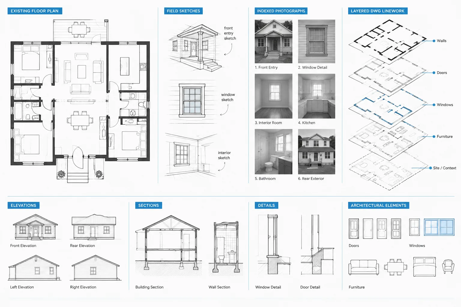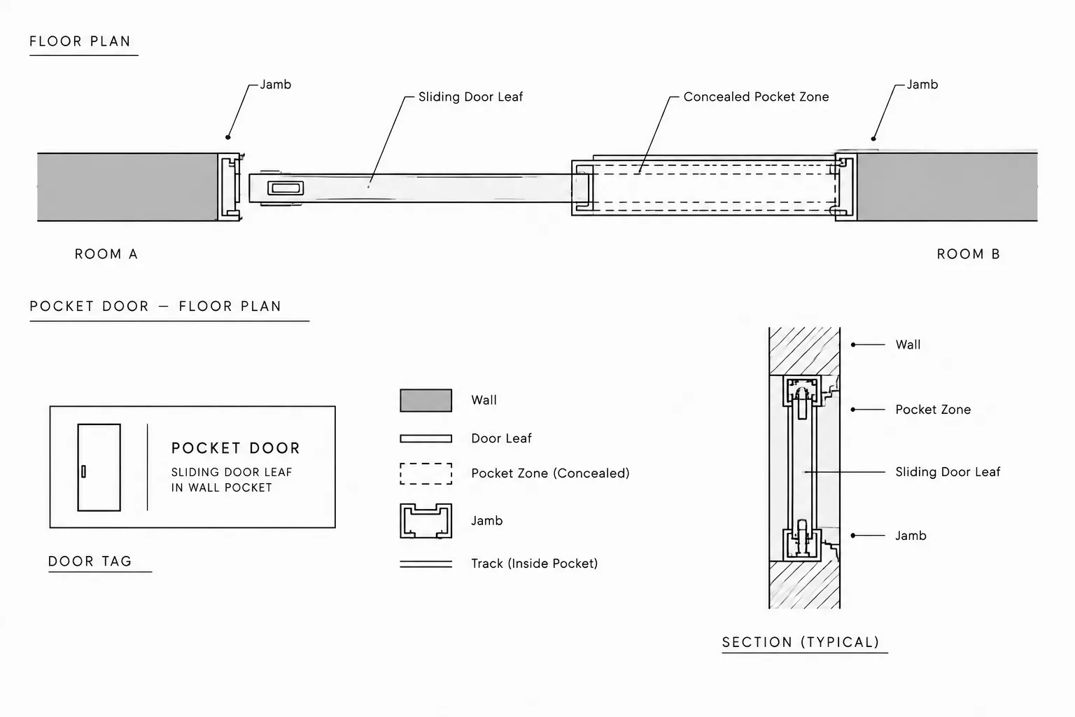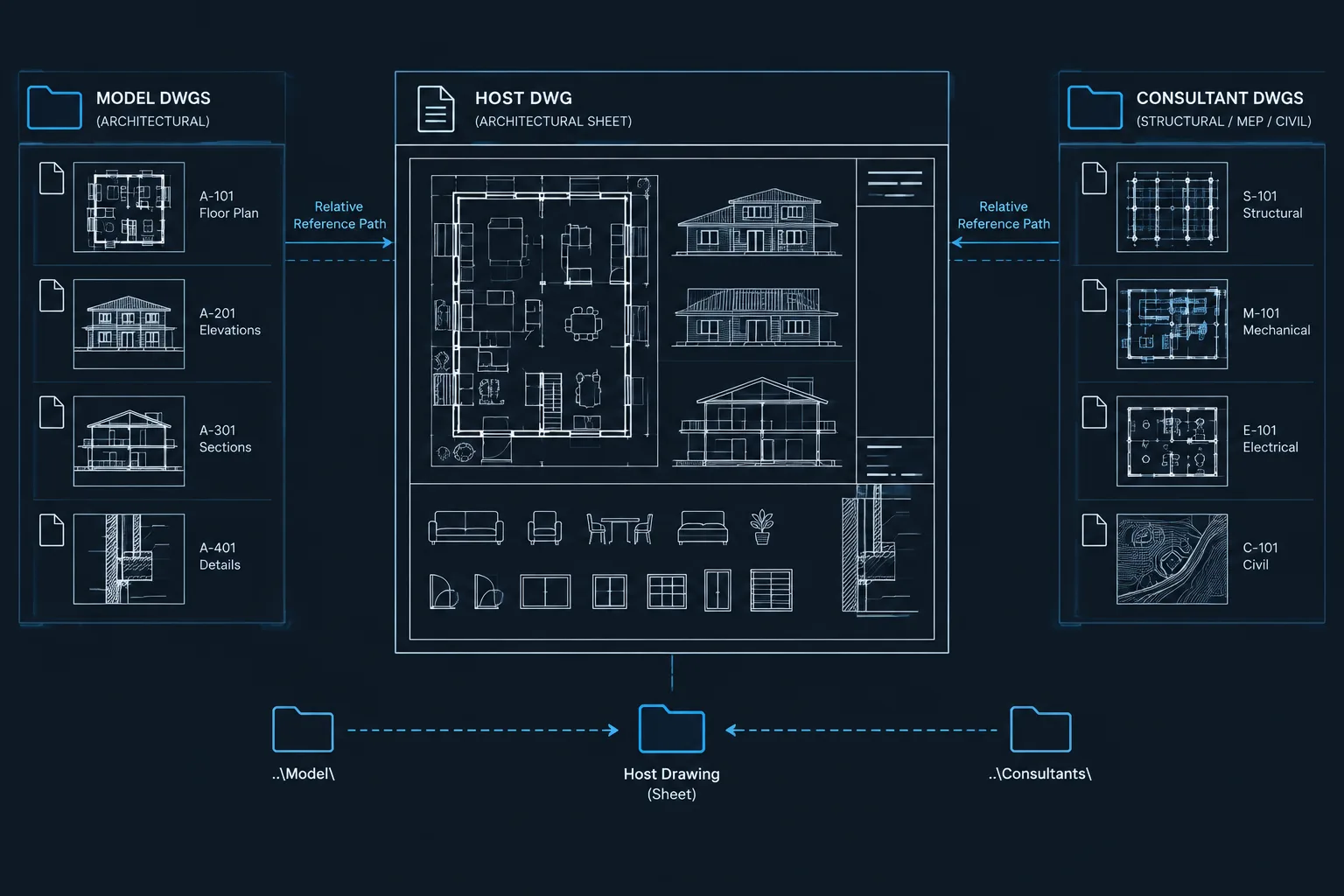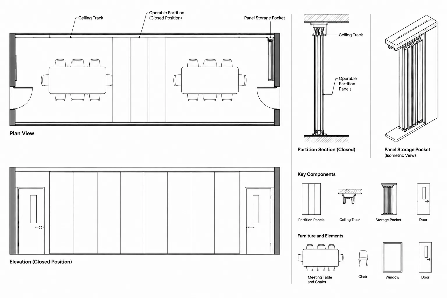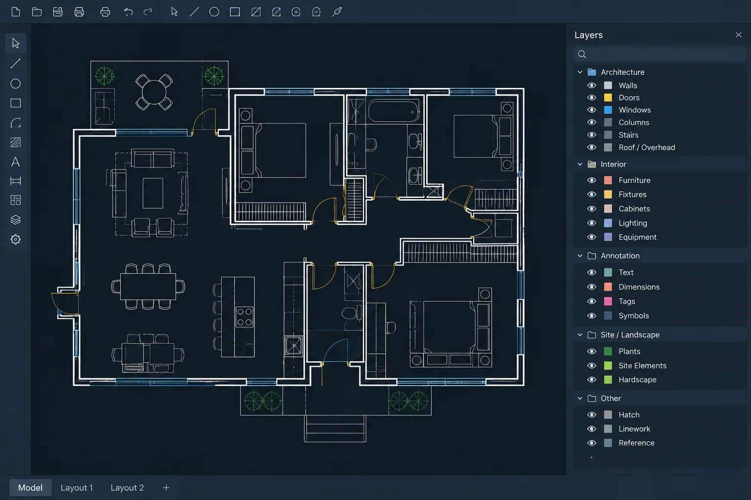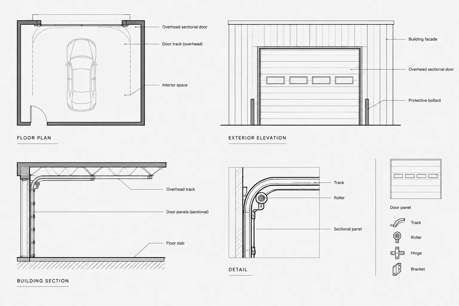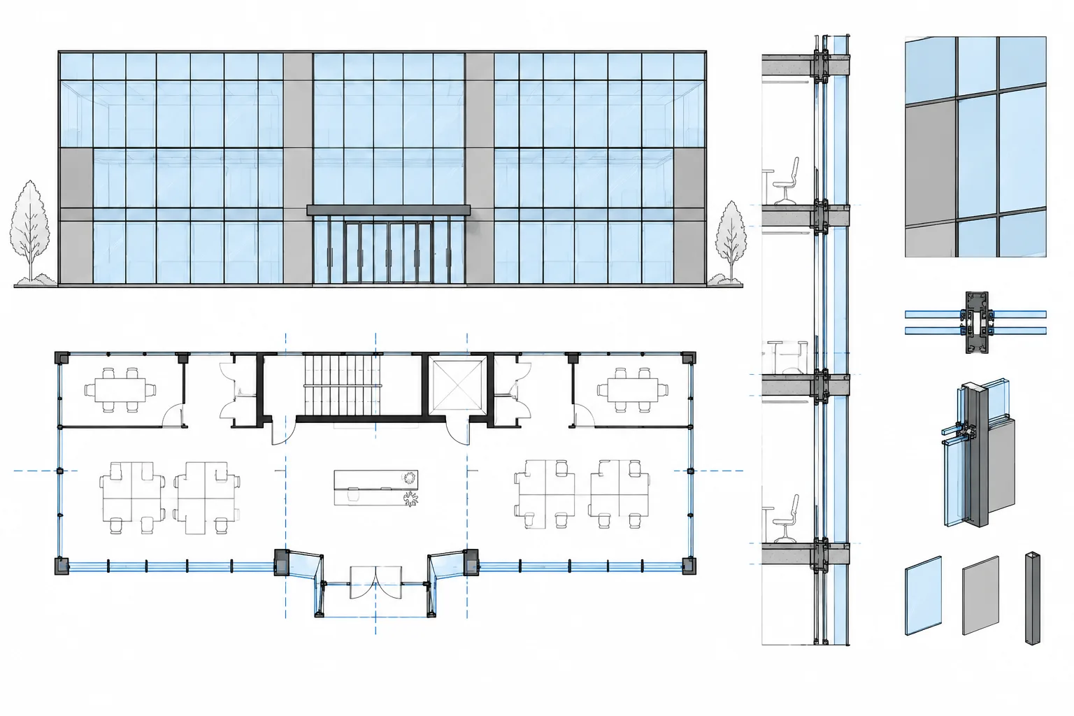
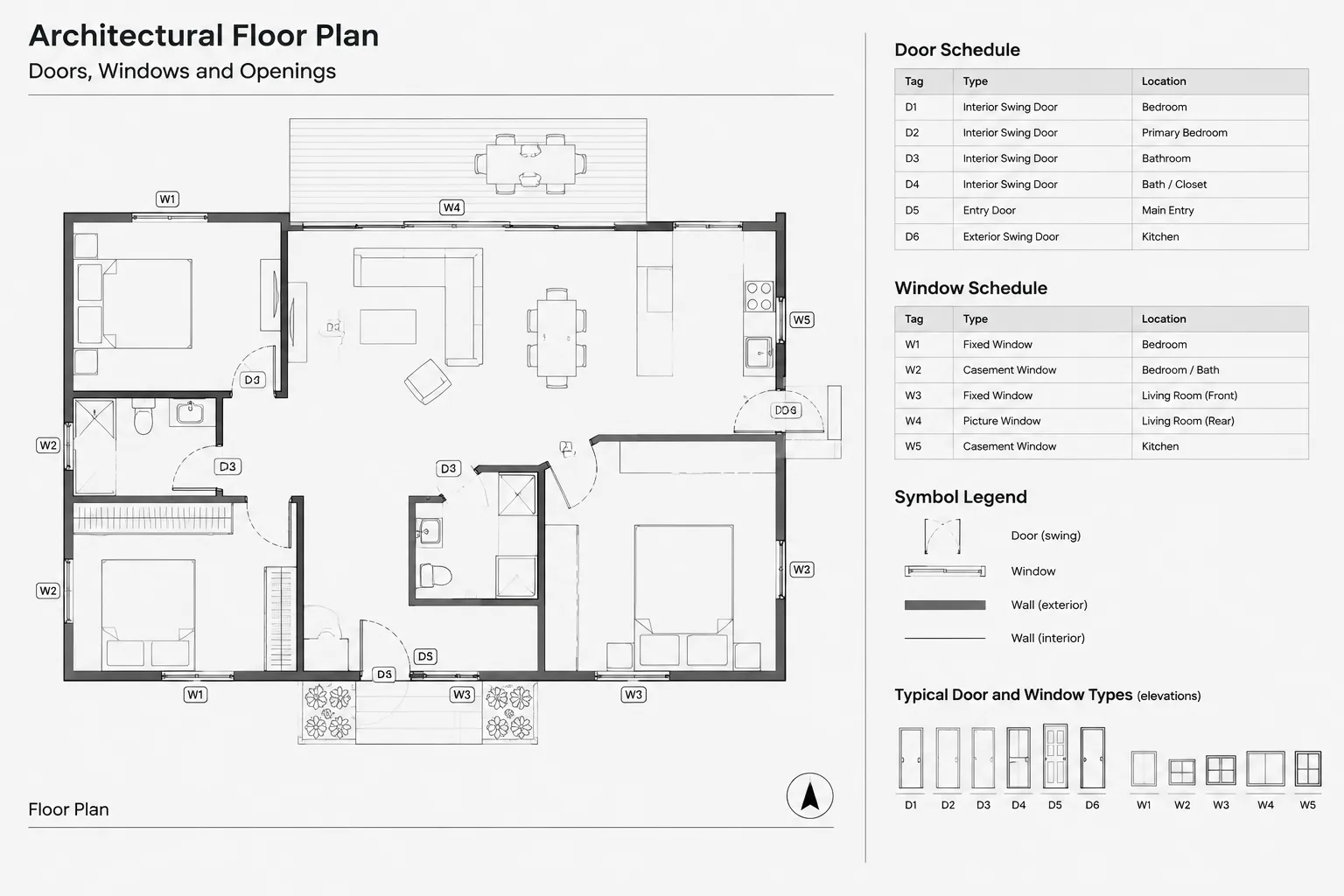
Door and window tags are small annotations with a large coordination role. Their identifiers connect openings in plans and elevations with schedules, details, and other project records. This guide explains how to establish tag logic, build controlled CAD symbols, place them clearly, and review them throughout drawing revisions.
Door and window tags may look like simple bubbles or polygons, but they connect several parts of an architectural drawing set. A tag identifies an opening on a plan or elevation, directs the reader to a schedule, and helps the project team track changes. When tags are placed inconsistently or edited independently from schedules, coordination errors can spread quickly.
A reliable tagging workflow is not based on appearance alone. It depends on a clear identification system, predictable placement, controlled CAD content, and regular comparison with plans, elevations, details, and schedules. The goal is for every tag to answer one question without ambiguity: which scheduled door or window does this symbol identify?
What a Door or Window Tag Represents
A tag is a drawing reference, not the door or window itself. Its displayed value usually points to an identifier in a corresponding schedule or project database. The identifier may represent an individual opening, a repeated type, or another project-specific classification.
Door and window identification systems are not always the same. A project might identify each door opening individually while assigning windows by type. Another project may use unique identifiers for both. Existing buildings, phased work, tenant areas, and multiple structures can require additional prefixes or classifications.
Before drafting tags, confirm what the identifier means on that project. Do not assume that a window tag always means a type or that a door identifier always follows a room number. The drawings, schedules, specifications, and project requirements must use the same logic.
Choose the Identification Strategy Before Tagging
Tagging becomes difficult when identifiers are improvised while plans are being annotated. Establish the project convention before placing large numbers of tags.
| Question | Coordination purpose |
|---|---|
| Does the identifier represent an opening or a type? | Determines whether repeated components share a tag value. |
| Are prefixes used? | May distinguish buildings, levels, phases, or component categories. |
| How are paired or grouped openings handled? | Prevents separate leaves or units from being tagged inconsistently. |
| How is existing work distinguished from new work? | Supports renovation and phased drawing coordination. |
| Where is the identifier controlled? | Clarifies whether the schedule, plan, or another project record is the primary source. |
The convention should be documented in the project drafting instructions or drawing notes. It should also allow reasonable changes without forcing the entire set to be renumbered unnecessarily.
Build Tags as Controlled CAD Symbols
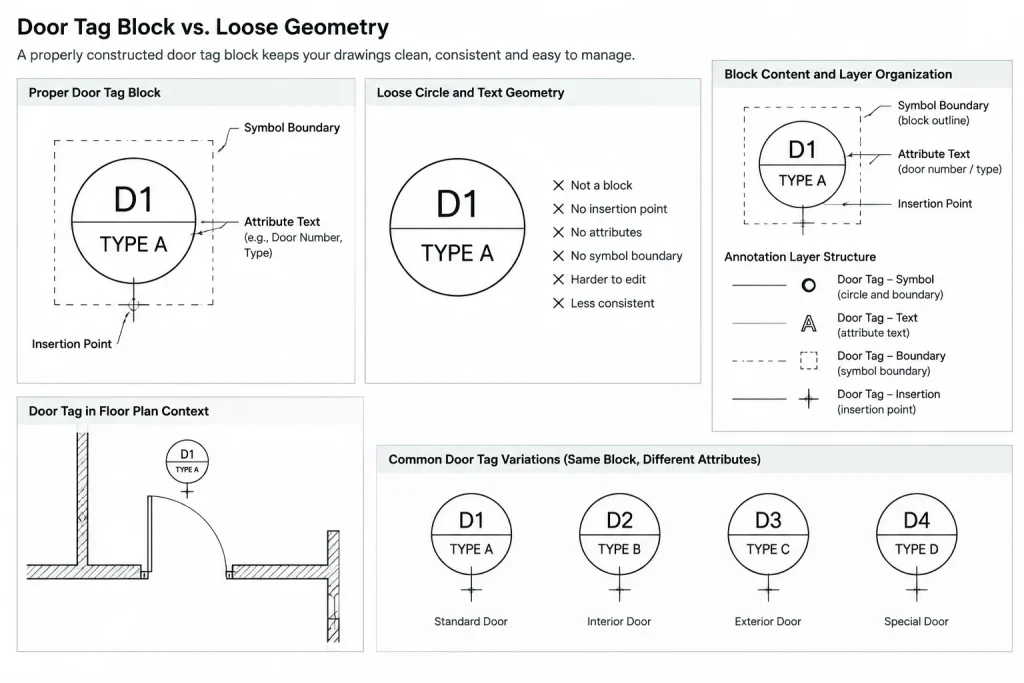
Door and window tags are usually best managed as blocks rather than loose circles, lines, and text. A block provides a consistent symbol, insertion point, text relationship, and editing method. Attributes can store the displayed identifier and, when useful, supporting information that does not need to be visible.
A practical tag block should include:
- A clear insertion point that supports predictable placement.
- A symbol boundary that remains legible at the intended plotted scale.
- An attribute or controlled text object for the identifier.
- Text alignment that accommodates expected identifier lengths.
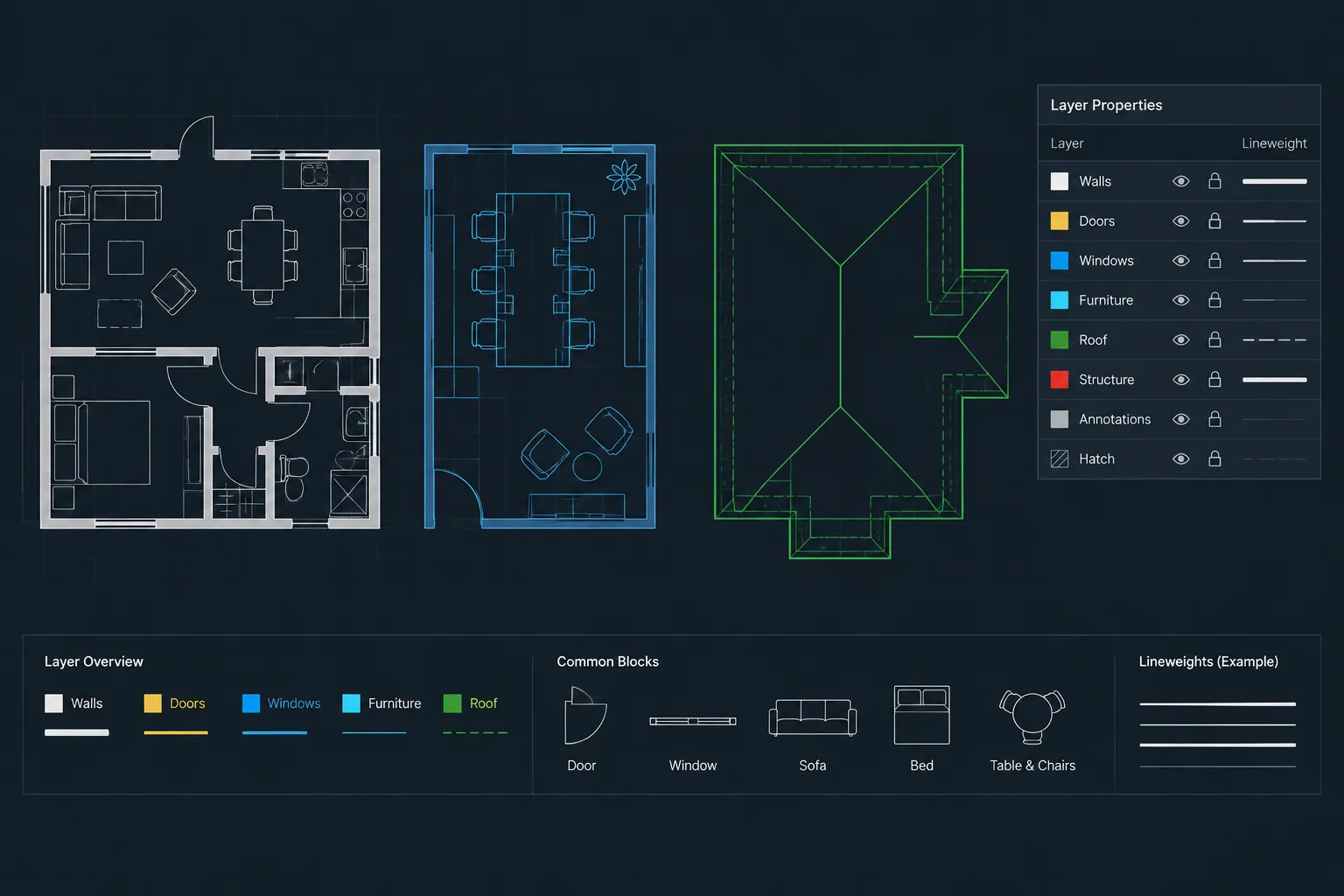
- Objects assigned to appropriate layers and properties.
- A defined orientation rule for plan and elevation use.
Avoid filling a tag with information already shown in the schedule. Adding size, material, operation, rating, or hardware data can make plans crowded and create more fields that must be coordinated. Display only what readers need to locate the related schedule entry unless the project has a documented reason for showing more.
Separate Symbol Geometry from Identification Data
The visible outline and the tag value serve different purposes. Keeping them separate within a block makes it easier to update graphics without altering identifiers. It also reduces the risk of accidentally deleting the text while stretching or moving the symbol.
If attributes are used, adopt a stable attribute naming convention. Changing attribute definitions after many tags have been placed can require additional synchronization and checking. Test the block in a temporary drawing before adding it to a project template or shared library.
Place Tags for Clarity, Not Just Proximity
A tag should be close enough to its opening to be understood without covering walls, dimensions, room names, equipment, or other annotations. Consistency is helpful, but rigid placement rules can fail in congested plans. Readability should take priority.
Door Tag Placement
Door tags are commonly placed near the associated opening, but the exact location depends on wall geometry, swing graphics, dimensions, and nearby notes. The tag should not be mistaken for a room tag or hardware reference. For paired doors, communicating devices, sidelights, or openings with multiple leaves, verify whether the schedule treats the assembly as one opening or several records before placing tags.
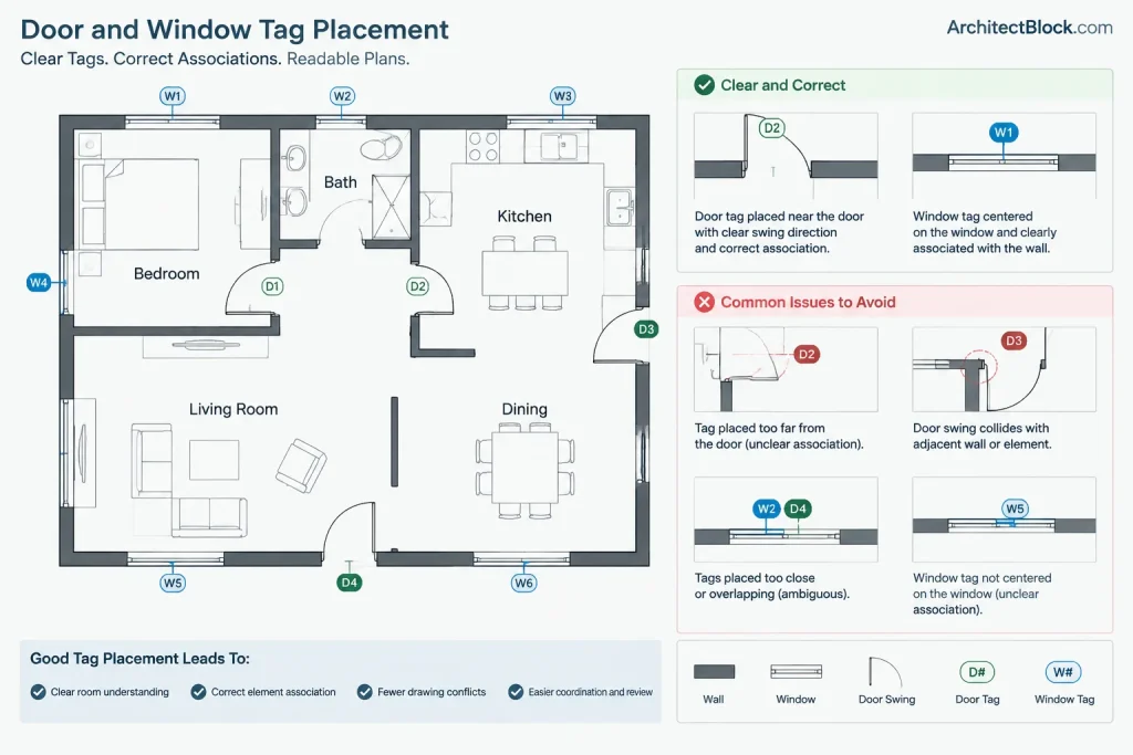
Do not rely on the swing arc alone to connect a distant tag to a door. If crowded geometry makes the association unclear, reposition surrounding annotations or use the project’s established leader convention.
Window Tag Placement
Window tags may appear in plans, exterior elevations, interior elevations, or enlarged views. Determine which view is the primary tagging location. Repeating the same tag across several views can improve navigation, but every repeated instance becomes another item that must remain coordinated.
In elevations, place tags so they do not obscure mullions, operation symbols, level references, or material annotations. Where several windows occur in a regular arrangement, do not assume one nearby tag clearly applies to all of them. Use a documented grouping method or tag each opening as required by the project convention.
Use Layers and Annotation Behavior Deliberately
Place tags on dedicated annotation layers rather than on door, window, or wall geometry layers. Separate layers allow tags to be shown, hidden, or overridden for different sheet purposes without affecting the architectural model graphics.
Door and window tags may use separate layers when the project benefits from independent visibility control. A smaller project may use a shared opening-tag layer if that remains clear and manageable. Layer names should follow the project’s established naming framework rather than introducing an isolated convention.
If tags are annotative, confirm that the required annotation scales are assigned and that the symbols appear correctly in every relevant viewport. If they are non-annotative, confirm that their model-space or paper-space workflow produces the intended plotted size. Mixing methods without a plan often causes duplicated, missing, or incorrectly scaled tags.
Coordinate Tags with the Schedule
A tag is only useful when its identifier matches a schedule record. Coordination should be a deliberate comparison, not an assumption based on visual similarity.
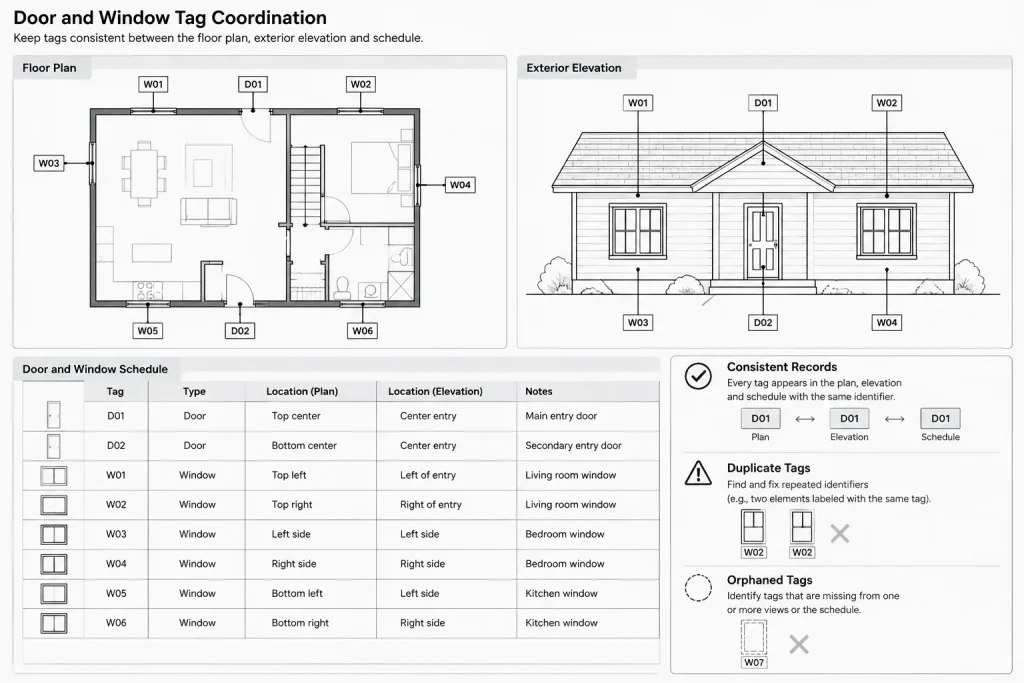
Use a repeatable sequence:
- Confirm that each tagged opening has a corresponding schedule entry.
- Check that every scheduled opening appears in the appropriate drawing view.
- Search for duplicate identifiers that should be unique.
- Review repeated type tags to confirm that the represented components are actually equivalent.
- Compare opening location, type, handing, operation, and other relevant information with the schedule and details.
- Check demolished, removed, or relocated openings for obsolete tags.
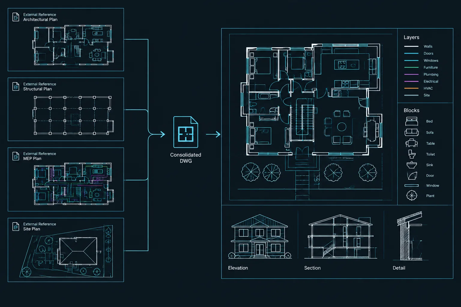
- Review references shown in enlarged plans, elevations, and details.
CAD data extraction or attribute reports can assist with counting and finding duplicate values when tags are structured consistently. However, an automated list cannot determine whether a tag points to the correct opening. Visual review remains necessary.
Handle Plan Changes Without Losing Control
Design revisions commonly add, remove, relocate, or change openings. A safe revision workflow updates the geometry, tag, schedule, and related views as one coordinated task.
When copying a tagged door or window, immediately decide whether the copied opening needs a new identifier or intentionally shares a type identifier. Blindly copying tags is a common source of duplicates. Similarly, deleting opening geometry does not necessarily delete a separate annotation block, so search the surrounding area for orphaned tags.
Renumbering should be controlled. Before changing an identifier, locate all places where it appears, including schedules, plans, elevations, sections, details, keynotes, and consultant backgrounds. A value that looks unused on one floor plan may still be referenced elsewhere.
Common Tagging Problems
- Duplicate unique identifiers: Often caused by copying an opening and its tag together.
- Orphaned tags: The opening was removed or moved, but its annotation remained.
- Unscheduled openings: A plan tag exists without a matching schedule row.
- Unplaced schedule records: The schedule contains an identifier that cannot be found in the drawings.
- Ambiguous grouping: One tag is placed near several openings without showing which components it covers.
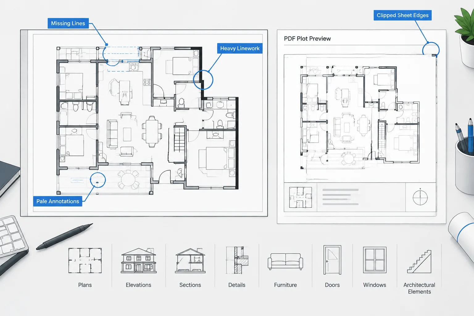
- Unreadable plotted tags: Symbols look acceptable in model space but collide or shrink in sheet viewports.
- Inconsistent orientation: Rotated tags slow plan reading or conflict with the project’s text convention.
- Manual text over blocks: Separate text can drift away from the symbol or be edited without updating stored data.
Final Quality-Control Checklist
- Confirm that door and window identification conventions are documented.
- Verify that tag values match schedule identifiers exactly.
- Check for duplicate, blank, and obsolete tag values.
- Review paired, grouped, and repeated openings carefully.
- Confirm that tags are associated with the intended opening.
- Check tag visibility and scale in every issued viewport.
- Look for collisions with dimensions, swings, room tags, and other notes.
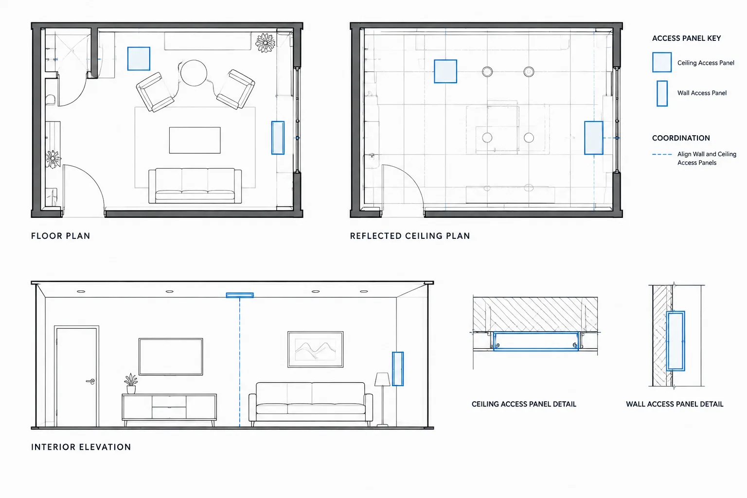
- Compare plans with elevations, sections, enlarged views, and details.
- Remove unused tags and resolve schedule entries that cannot be located.
- Plot or publish a review sheet rather than relying only on the model-space display.
Well-coordinated door and window tags make a drawing set easier to navigate and reduce uncertainty during review. The most reliable workflow treats each tag as part of a connected information system rather than as an isolated graphic. Establish the identification logic first, use controlled CAD symbols, place them clearly, and review tags and schedules together whenever openings change.
Define Responsibility for Tag Data
A coordinated workflow should identify where door and window information is controlled and who is responsible for reviewing changes. When several drawings or team members can edit the same identifier independently, conflicting values can remain unnoticed until a formal drawing review.
Project procedures should distinguish between the authoritative identifier and the repeated graphic references to that identifier. The schedule may serve as the primary project record, or the project may use another controlled source. Whatever method is selected, plans, elevations, details, and schedules should follow the same convention.
Review Tags in Drawing Context
Tag checks should include more than a search for matching text. A correct identifier can still be attached to the wrong opening, obscured by another annotation, or repeated in a view where its meaning is unclear. Review each tag in the sheet and viewport context in which readers will encounter it.
- Association: Confirm that the symbol clearly identifies the intended door, window, or grouped assembly.
- Legibility: Check the plotted symbol, text alignment, orientation, and surrounding annotation.
- Record matching: Compare the displayed value with the corresponding schedule entry or controlled project record.
- View coordination: Verify repeated references in plans, elevations, sections, and enlarged views.
- Revision status: Remove obsolete references and resolve new, relocated, or changed openings.
Treat Exceptions as Documented Decisions
Renovation areas, grouped openings, repeated types, and phased work may not fit the usual tagging pattern. Avoid solving these conditions with improvised text or one-off symbols. Record the exception in the project drafting instructions and apply it consistently wherever the condition appears.
This approach makes quality control easier because reviewers can distinguish an intentional exception from a drafting error. It also helps future editors understand why a tag differs from the surrounding convention.
Frequently Asked Questions
Should door and window tags use the same identification system?
Not necessarily. Door identifiers may represent individual openings while window identifiers may represent types, but the method depends on the project. Define each system before tagging and make its meaning clear in the schedules and drawing conventions.
Should tags be blocks or separate lines and text?
Controlled blocks are generally easier to place, edit, and review consistently. Attributes can hold identifiers while the block maintains the symbol boundary, insertion point, alignment, and layer behavior.
Where should a door or window tag be placed?
Place it close enough to make the association clear without covering opening graphics, dimensions, room information, or other notes. If proximity is not sufficient, follow the project’s established leader or grouping convention.
Can one tag identify several openings?
Only when the project convention clearly defines that grouping. The schedule and drawings must agree on whether the tag represents an assembly, a repeated type, or an individual opening.
How should copied tags be handled?
Review the copied identifier immediately. A copied opening may require a new unique value or may intentionally retain a shared type value. Do not assume the copied tag is correct without checking the identification strategy.
Can attribute extraction replace visual review?
No. Structured tag data can help locate blanks, duplicates, and unmatched values, but it cannot confirm that a symbol points to the correct opening or remains readable on the issued sheet.
What should be checked after an opening changes?
Review the opening geometry, tag, schedule entry, and every related plan, elevation, section, detail, or enlarged view. Also check for obsolete tags left behind after geometry is moved or deleted.