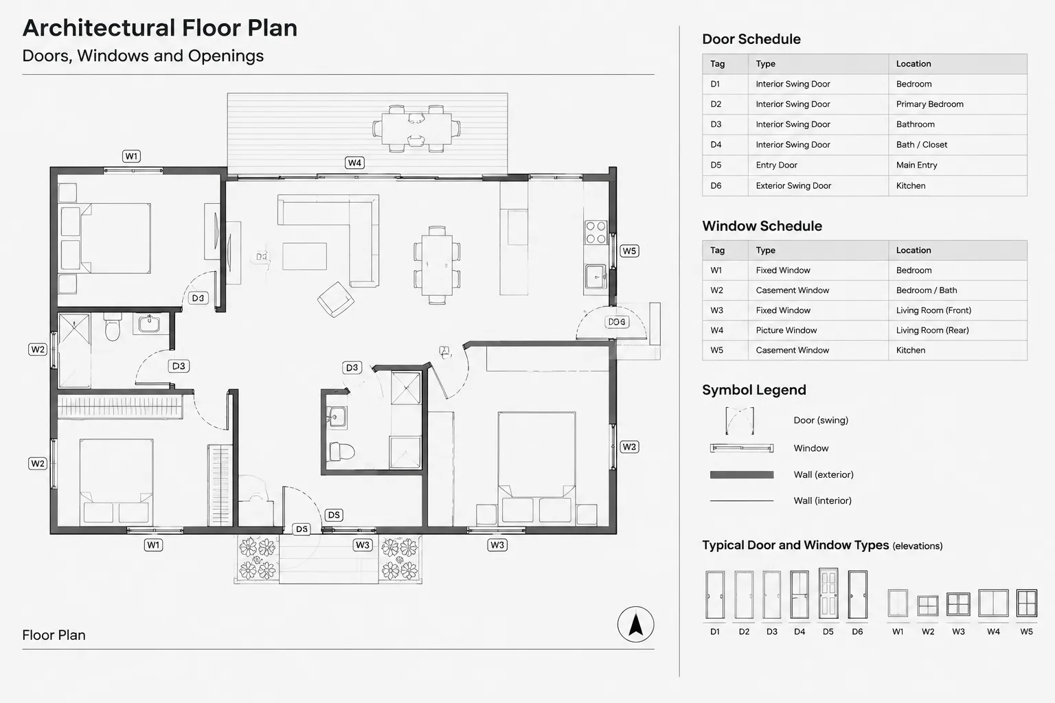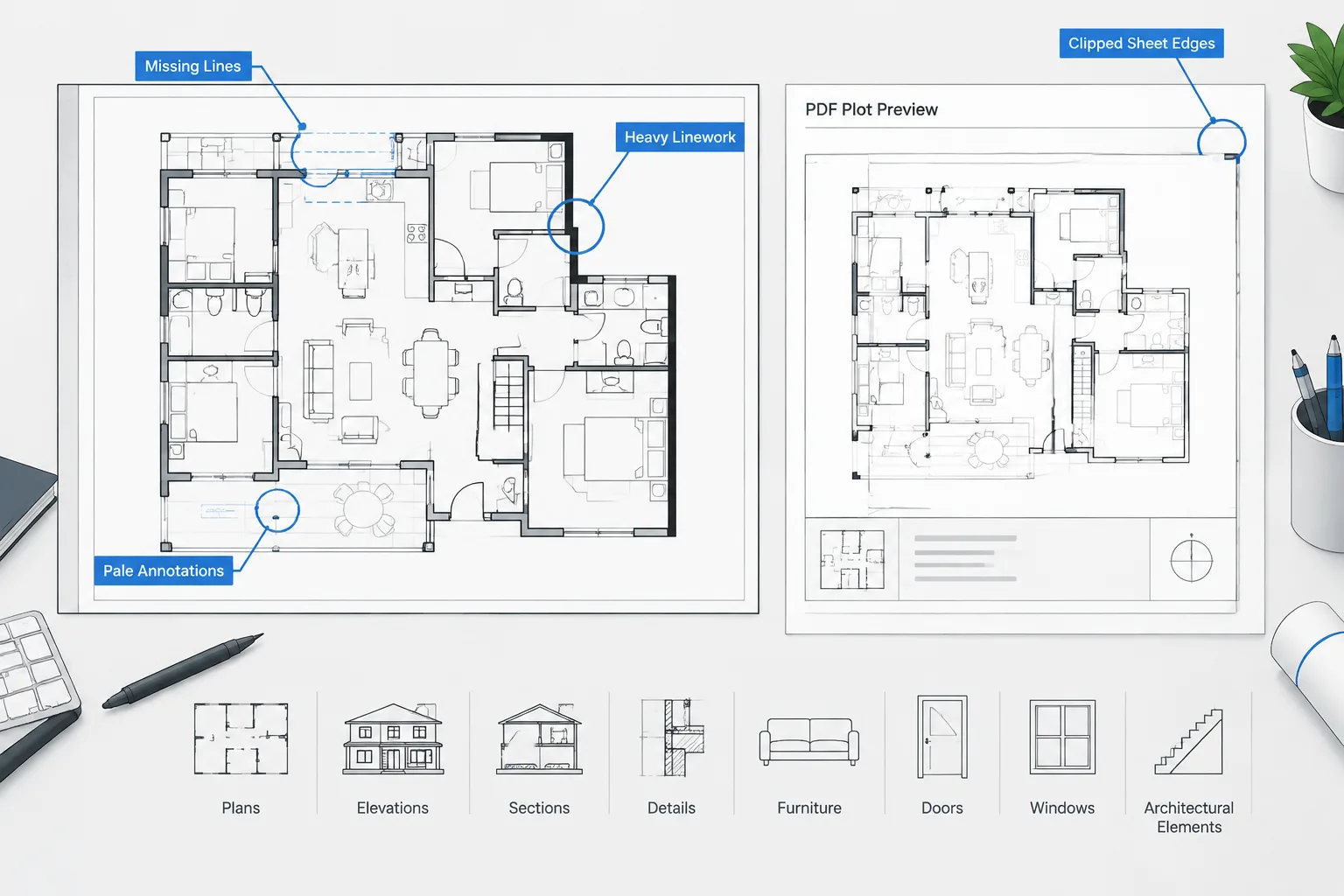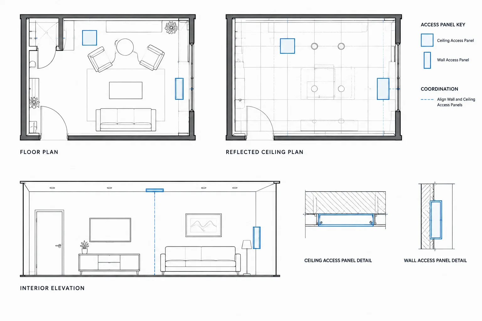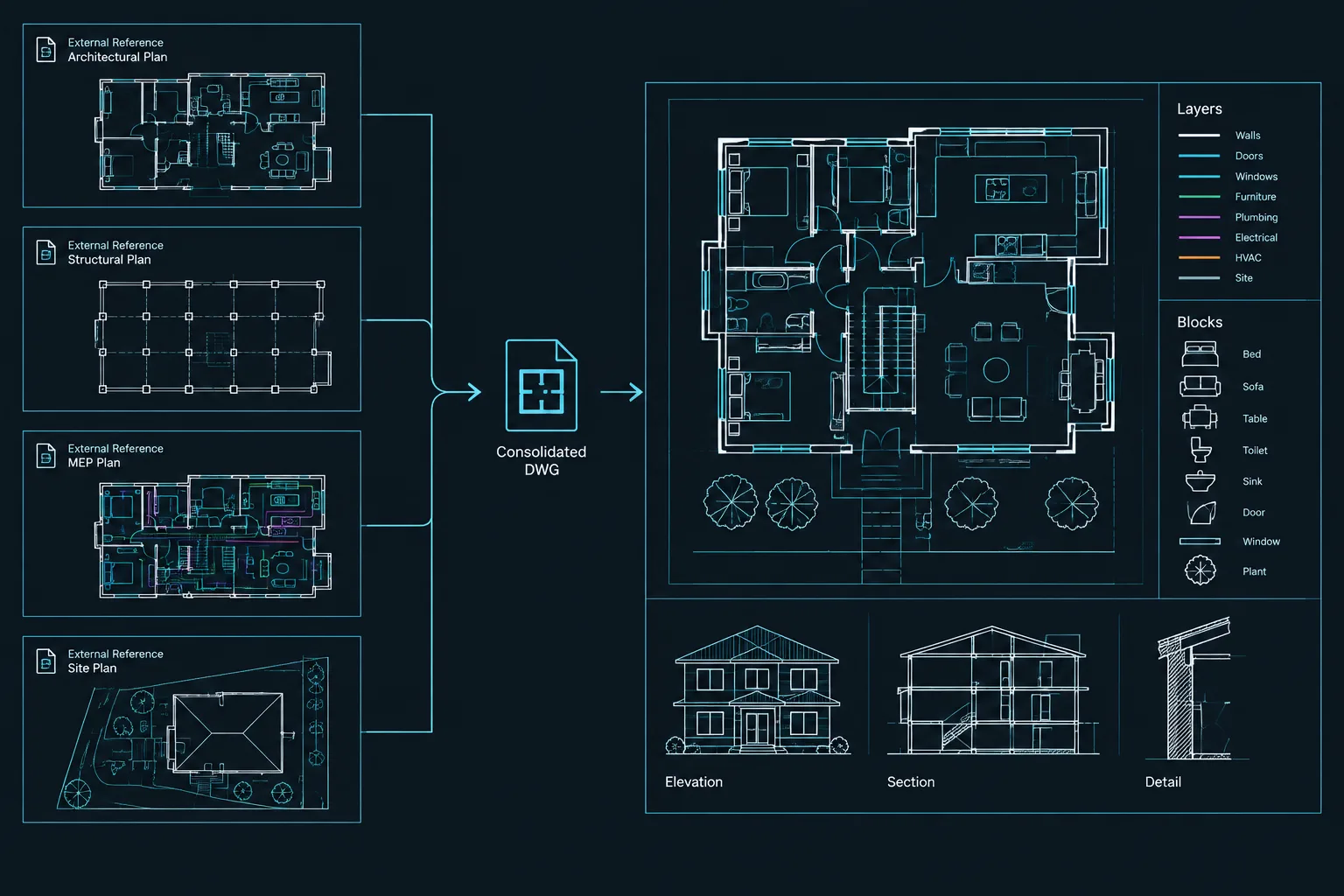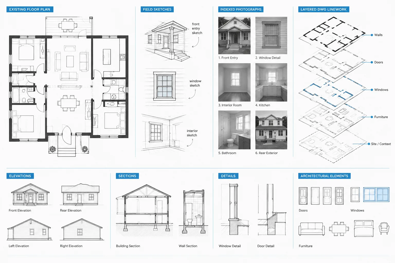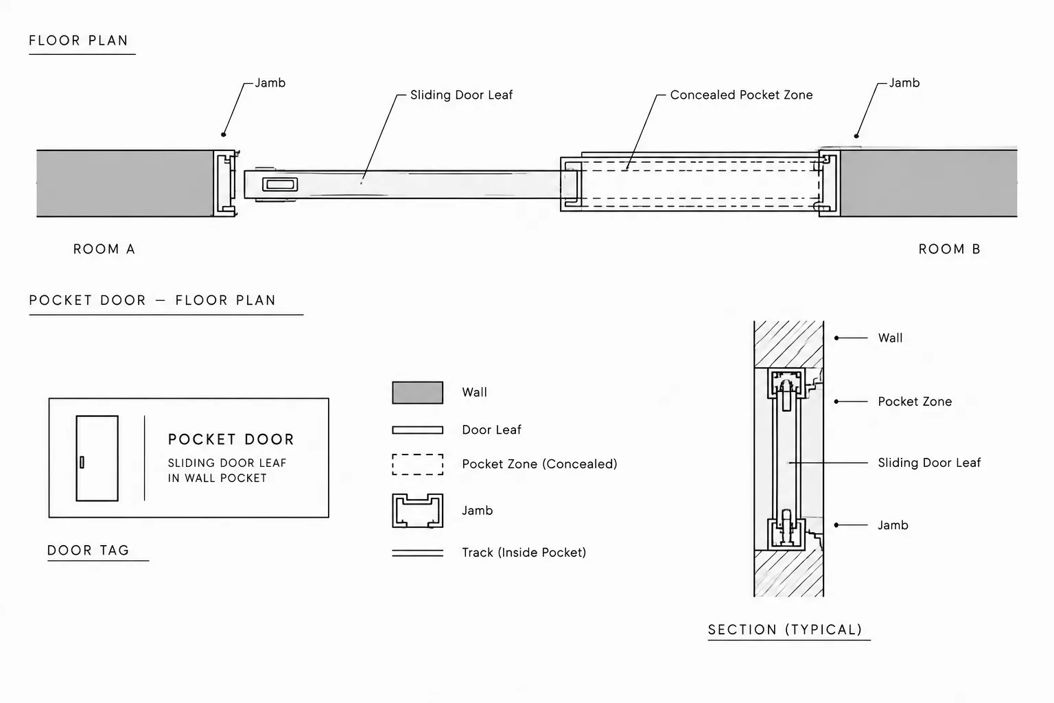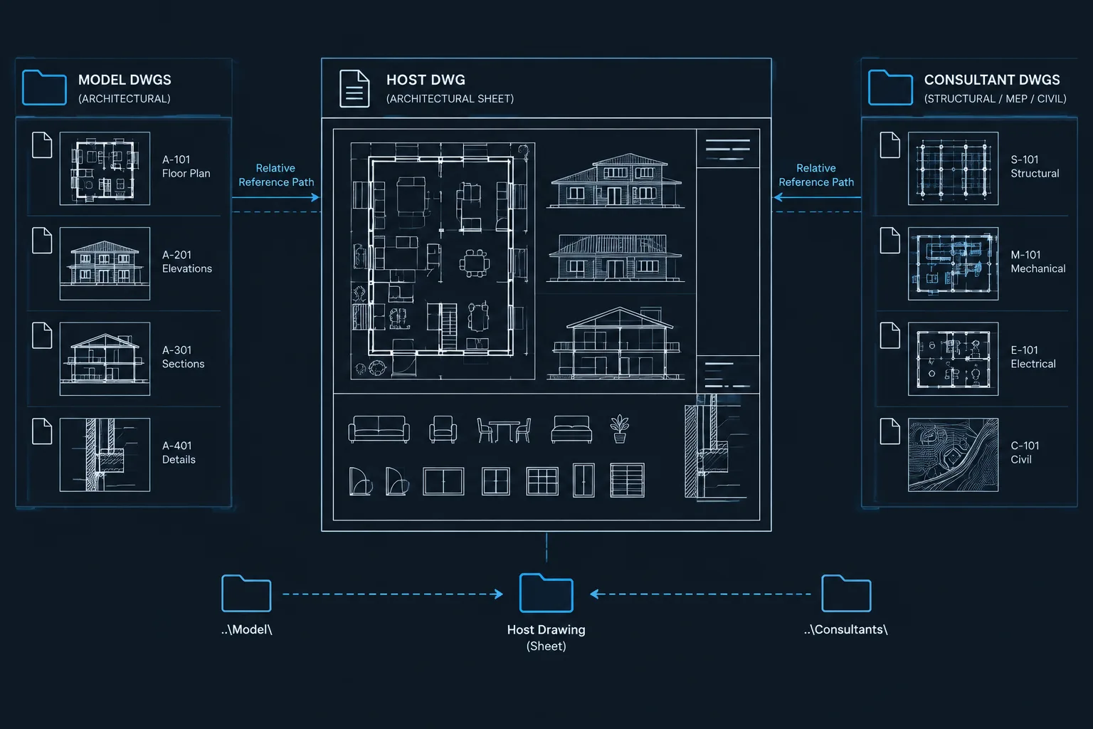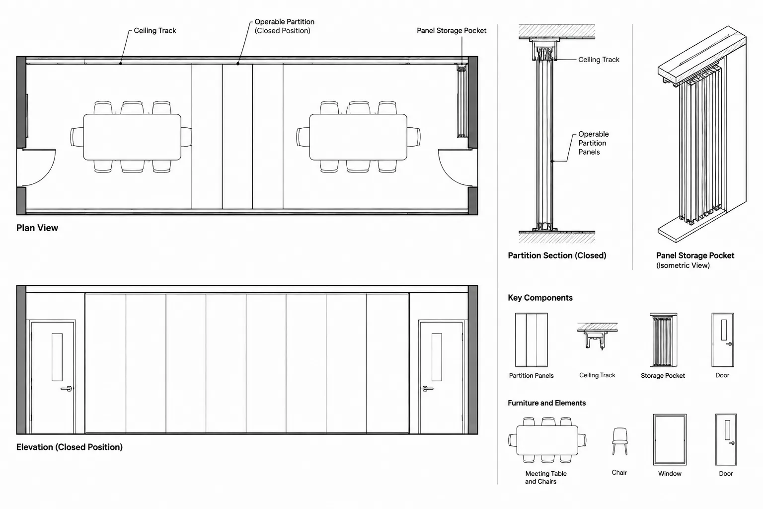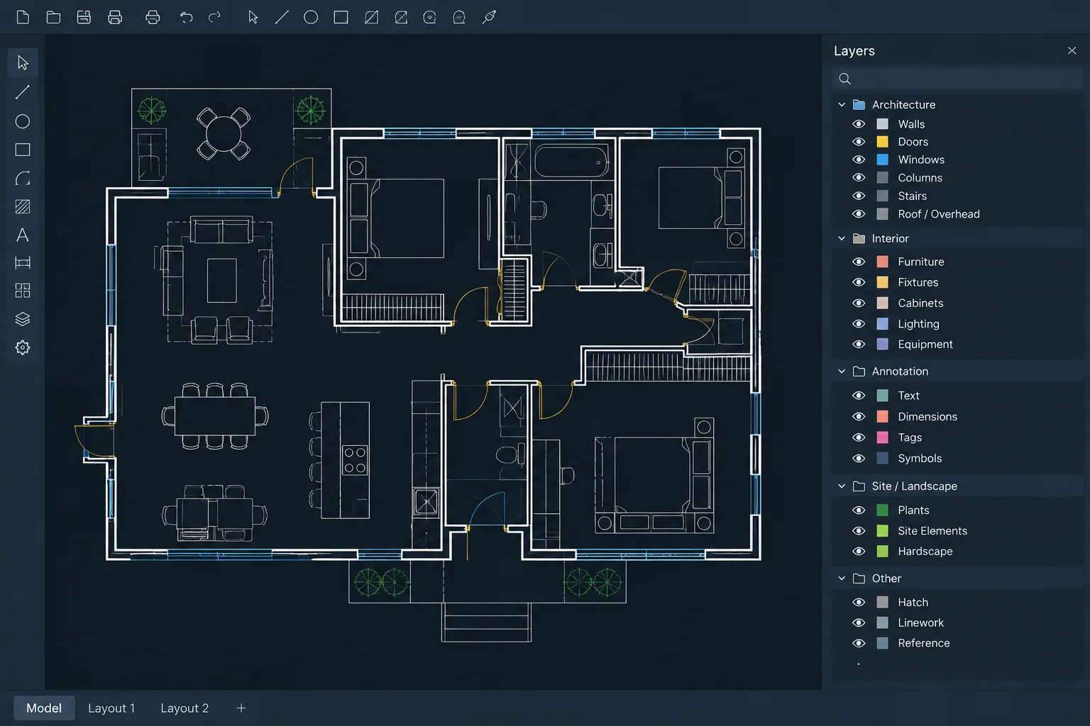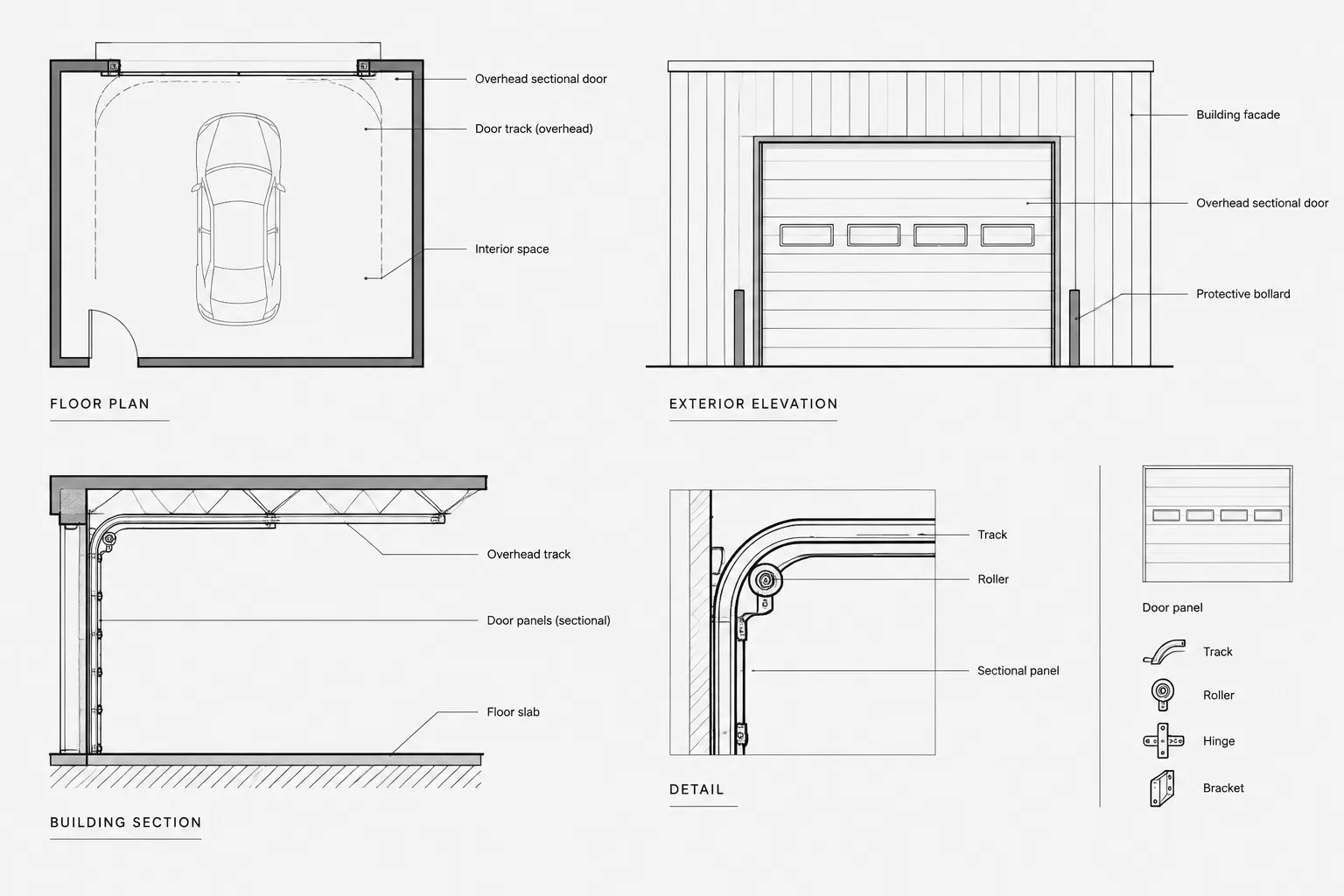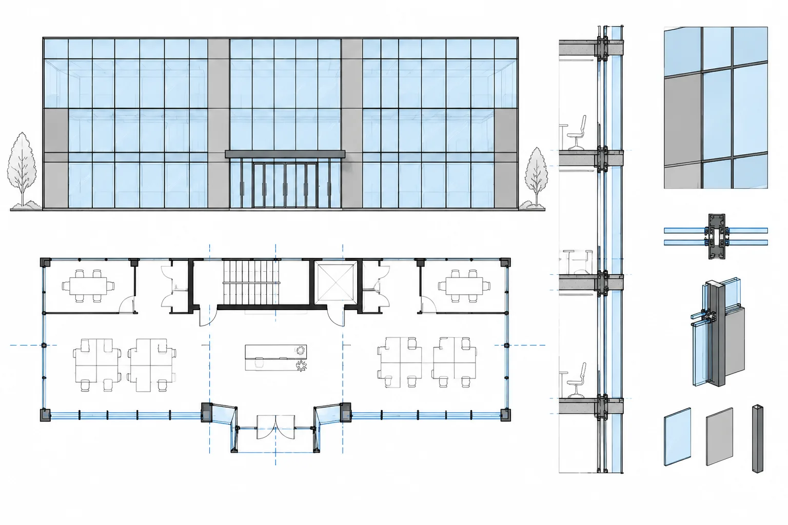
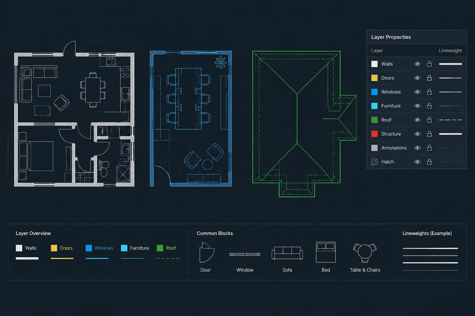
Reusable architectural blocks depend on more than accurate geometry. Their internal layers and object properties determine whether doors, fixtures, furniture, symbols, and annotations respond correctly after insertion into a project drawing.
This guide explains how Layer 0, ByLayer, and ByBlock interact within an AutoCAD block. It also provides a practical framework for choosing the appropriate behavior, auditing inconsistent blocks, and keeping a shared DWG library predictable.
Architectural block problems often begin with a simple property decision. A door symbol may refuse to match the surrounding plan, a furniture block may plot too heavily, or one component inside a fixture may remain the wrong color after insertion. These issues are frequently caused by the relationship between Layer 0, ByLayer properties, ByBlock properties, and the layer on which the block reference is inserted.
Understanding that relationship is essential when building or cleaning a reusable DWG library. It allows one block definition to respond predictably in different drawings without forcing users to edit its internal geometry each time.
The four parts of block property behavior
To diagnose a block correctly, separate four concepts that are easy to confuse:
- Object layer: The layer assigned to a line, arc, hatch, text object, or other entity inside the block definition.
- Object properties: Properties such as color, linetype, and lineweight assigned directly to that internal entity.
- Block reference layer: The layer on which the inserted instance of the block is placed.
- Block reference properties: Any direct property overrides applied to the inserted block reference.
A block can therefore contain objects on several layers while the block reference itself sits on another layer. Changing the insertion layer does not automatically move every internal object to that layer. The result depends on how the objects in the definition were constructed.
What Layer 0 does inside a block
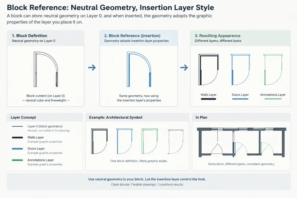
Layer 0 has special behavior when used for geometry inside a block definition. If an internal object is on Layer 0 and its relevant properties are set to ByLayer, it can visually follow the layer of the inserted block reference.
For example, a generic chair block built with Layer 0 geometry can be inserted on a furniture layer. Its geometry then displays according to the furniture layer’s assigned properties. The same definition could be inserted on a demolition-furniture layer and respond to that layer instead.
This makes Layer 0 useful for generic block geometry that should take on the graphic identity of its insertion layer. It does not mean that every object in every block should be placed on Layer 0. Components that need an independent layer identity may belong on dedicated layers.
Why inserting every block on Layer 0 is usually unhelpful
A well-built Layer 0 block gains its flexibility from the layer of the block reference. If the reference is also left on Layer 0, the block no longer participates clearly in the project layer structure. It may be harder to isolate, freeze, plot, or manage by architectural category.
A more useful workflow is to create appropriate internal behavior and then insert each block on a project layer that describes its role, such as furniture, plumbing fixtures, door tags, or equipment.
What ByLayer means
ByLayer tells an object to use the color, linetype, or lineweight assigned to its own layer. For ordinary model-space geometry, this is the foundation of consistent CAD standards. Changing a layer property can update all eligible objects assigned to that layer.
Inside a block, ByLayer still refers to the internal object’s layer. If the object is on a named layer, it uses that named layer’s properties. If it is on Layer 0, the special block behavior allows it to follow the block reference’s insertion layer.
For most general architectural block geometry, Layer 0 combined with ByLayer is a dependable starting point. It keeps the definition neutral and allows the project layer system to control its appearance.
What ByBlock means
ByBlock allows an internal object to receive a property from the block reference rather than directly from its internal layer. If the corresponding block-reference property has not been overridden, the final appearance may continue to be governed by the reference’s layer.
This behavior can be useful when selected parts of a block need to respond to a property assigned to the entire inserted block. It can also introduce confusion because users may not realize that a reference-level override is controlling internal geometry.
ByBlock should therefore be used deliberately rather than as a default replacement for ByLayer. Before adopting it in a shared library, confirm that the expected editing workflow is clear to everyone who will use the block.
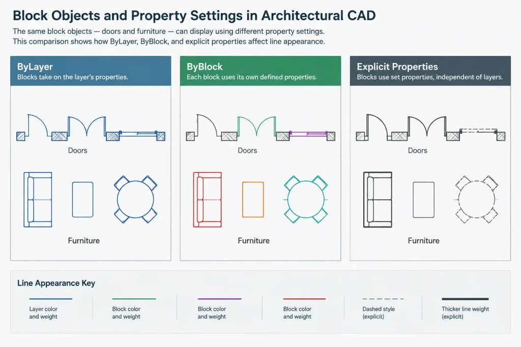
Common configurations compared
| Internal setup | Typical result | Practical use |
|---|---|---|
| Layer 0 with ByLayer properties | Geometry generally follows the block reference’s insertion layer | Generic symbols, furniture outlines, fixtures, and other reusable components |
| Named internal layer with ByLayer properties | Geometry follows that named layer, regardless of the reference layer | Components requiring independent visibility or plotting control |
| ByBlock property | Geometry can respond to a property assigned to the block reference | Controlled exceptions where reference-level overrides are intentional |
| Explicit object property | Geometry retains the assigned color, linetype, or lineweight | Limited special cases that must remain visually fixed |
The table describes general behavior, but block nesting and property overrides can make the final result more complex. Test representative blocks in the same environment used for project production and plotting.
When named layers belong inside an architectural block
Using Layer 0 for all geometry can make a simple block flexible, but more complex architectural components may need internal layer separation. A block might include plan graphics, overhead information, clearance zones, annotation, or non-plotting construction geometry. Keeping these parts on dedicated layers can provide useful visibility control.
Before adding named layers to a library block, ask:
- Does the component need to be hidden independently from the rest of the block?
- Must one part use a different linetype or plotting treatment?
- Will the internal layer names fit the receiving project’s layer conventions?
- Could the same result be achieved more clearly with separate blocks or external annotation?
Named internal layers travel with the block definition when it enters another drawing. Poorly named or unnecessary layers can clutter the receiving file, so internal layer complexity should provide a real coordination benefit.
A reliable workflow for building library blocks
1. Decide what the insertion layer should control
Start with the intended user experience. Determine whether the complete block should adopt one project-layer appearance or whether selected components require independent control.
2. Set neutral geometry intentionally
For geometry intended to follow the insertion layer, place it on Layer 0 and set color, linetype, and lineweight to ByLayer. Check every object rather than assuming all selected geometry shares the same properties.
3. Keep necessary internal layers purposeful
Assign a named layer only when the internal component genuinely needs separate control. Use project-compatible naming where possible, and avoid importing unrelated layers from source drawings.
4. Review annotation separately
Text, attributes, tags, and other annotation may require behavior different from the visible component outline. Check their style, layer, orientation, and plot appearance independently. Do not assume that geometry settings are automatically appropriate for text.
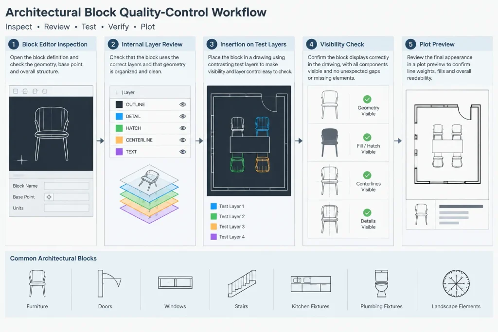
5. Test on contrasting layers
Insert the finished block on several test layers with visibly different properties. Confirm that neutral geometry follows the insertion layer, fixed components remain fixed, and named internal layers respond as intended.
6. Test visibility and plotting
Freeze or turn off relevant layers to verify which parts disappear. Then review a plotted or previewed sheet using the project’s actual plotting method. A block that looks acceptable on screen may still have inconsistent lineweight or linetype output.
How to troubleshoot a block that will not match its layer
When a block remains the wrong color or lineweight, changing its insertion layer repeatedly may not solve the problem. Use a structured inspection:
- Confirm the layer of the block reference.
- Check whether the block reference has direct color, linetype, or lineweight overrides.
- Open the block definition and inspect the layers of its internal objects.
- Look for explicit object properties instead of ByLayer or intentional ByBlock settings.
- Check nested blocks, because the unexpected object may belong to a separate definition.
- Inspect hatches, attributes, and text individually; they may not share the outline’s settings.
- Retest after editing the definition to confirm that existing references update as expected.
A frequent mistake is selecting only the visible outer lines while missing smaller objects, solid fills, or overlapping geometry with different properties. Isolating and inspecting internal components can expose these exceptions.
Quality-control rules for shared DWG libraries
Consistency matters more than forcing every block into a single construction method. A library should establish a documented approach for simple symbols, layered components, annotation blocks, and nested assemblies.
- Use Layer 0 and ByLayer for neutral geometry that should follow the insertion layer.
- Use named internal layers only when they provide necessary visibility or graphic control.
- Use ByBlock selectively and document why it is needed.
- Avoid accidental hard-coded properties that bypass layer management.
- Test blocks in a clean drawing as well as in a representative project file.
- Verify screen display, layer visibility, and plotted output before publishing a block.
Layer 0, ByLayer, and ByBlock are not competing settings. They are different tools in a property-control system. When their roles are planned, architectural blocks remain flexible, easy to classify, and predictable across drawings. When they are mixed without intent, even a simple symbol can become difficult to manage.
A simple way to predict block appearance
When a block looks wrong, trace property control from the visible object outward. First inspect the entity inside the definition, then its internal layer, the properties of the inserted block reference, and finally the layer containing that reference. This sequence helps reveal where the displayed color, linetype, or lineweight originates.
The most maintainable setup is usually the one with the fewest intentional exceptions. Neutral geometry can follow the insertion layer, while components needing separate visibility or graphic treatment can remain on purposeful named layers. Direct overrides and ByBlock behavior should have a clear reason rather than being remnants of earlier editing.
Questions to ask before approving a library block
- Classification: Does the block reference sit on a project layer that clearly describes the object?
- Inheritance: Does geometry intended to be neutral actually respond to the insertion layer?
- Exceptions: Are fixed properties, named internal layers, and ByBlock settings deliberate?
- Completeness: Have hatches, attributes, text, fills, and nested definitions been inspected as well as outlines?
- Portability: Will the block introduce unnecessary layers or confusing property behavior into another drawing?
- Output: Has the block been checked both on screen and through the project plotting workflow?
This review separates block-definition problems from project-layer problems. It also makes corrections easier to document, repeat, and apply consistently across an architectural CAD library.
Frequently asked questions
Should all geometry inside an architectural block be on Layer 0?
No. Layer 0 is useful for neutral geometry intended to follow the block reference layer. Named internal layers remain appropriate when parts of the block require independent visibility or graphic control.
Why does a block stay the same color after I move it to another layer?
The internal objects may be on named layers, use explicit color assignments, or respond to a block-reference override. Nested blocks, hatches, text, and attributes may also have properties different from the visible outline.
Is ByBlock the same as ByLayer?
No. ByLayer obtains the relevant property from the object’s layer. ByBlock allows an internal object to respond to a property assigned at the block-reference level. Their results can appear similar in some situations, but the control path is different.
Can one block contain both ByLayer and ByBlock objects?
Yes, but the mixture should be intentional and documented. Otherwise, users may have difficulty understanding why only part of an inserted block responds to a reference-level property change.
Why do named internal layers appear in the receiving drawing?
Layers used by objects within a block definition become part of the drawing that receives the definition. This is why reusable blocks should avoid unnecessary or poorly named internal layers.
What should I inspect first when a block plots incorrectly?
Start with the block reference layer and its direct property overrides. Then inspect the internal entities, including their layers and property assignments. Finish by checking nested content and reviewing the block with the project’s actual plotting method.