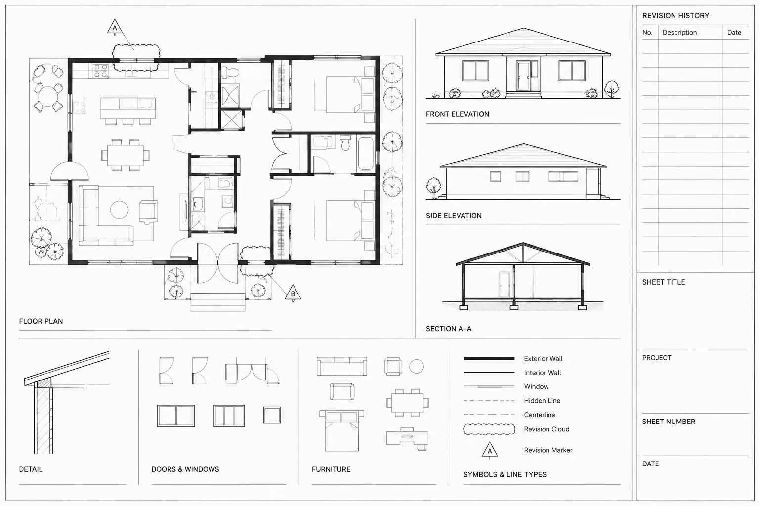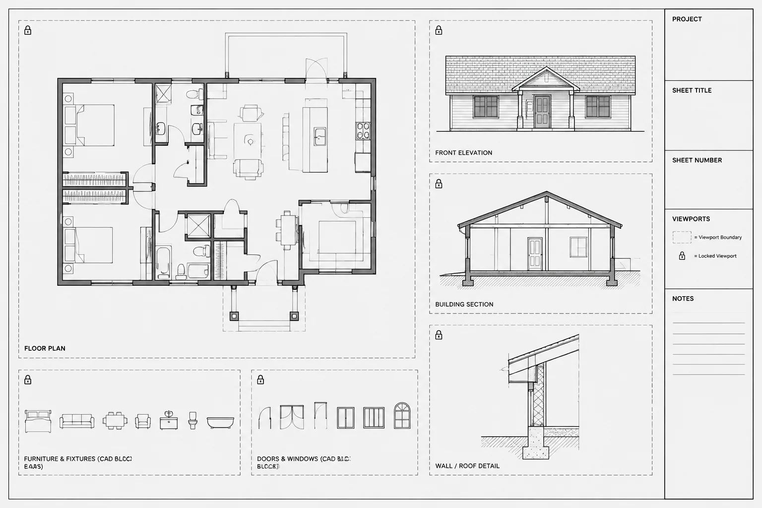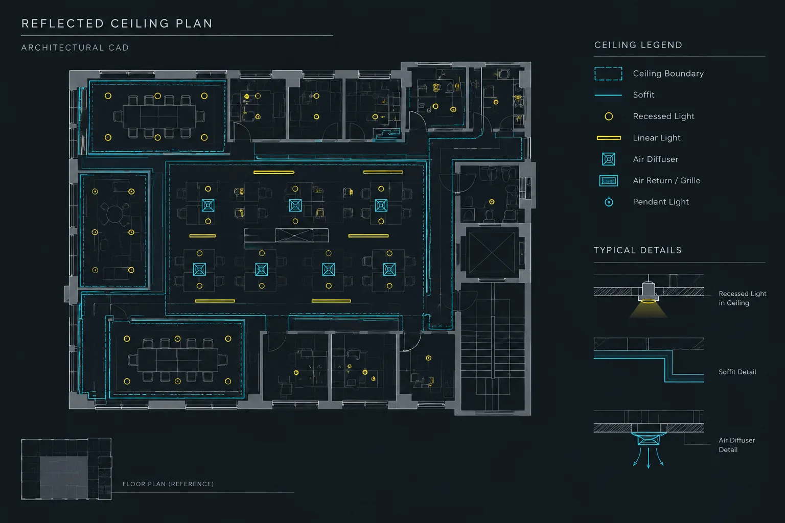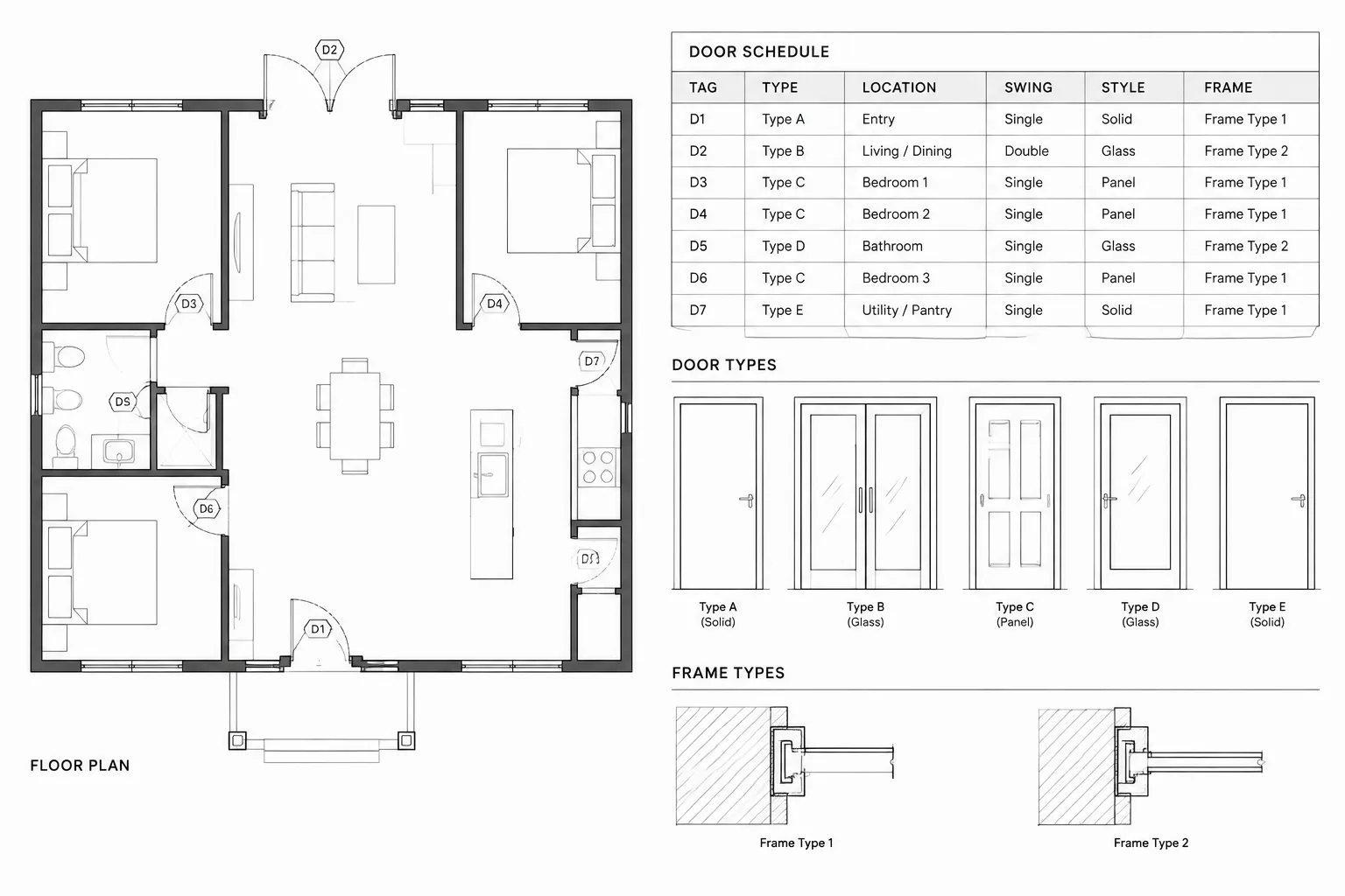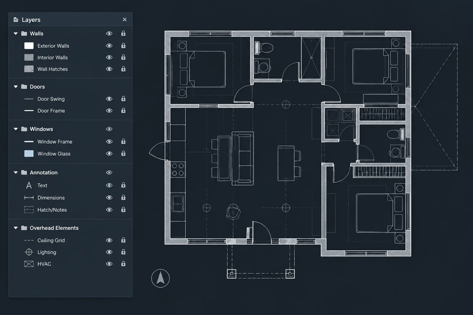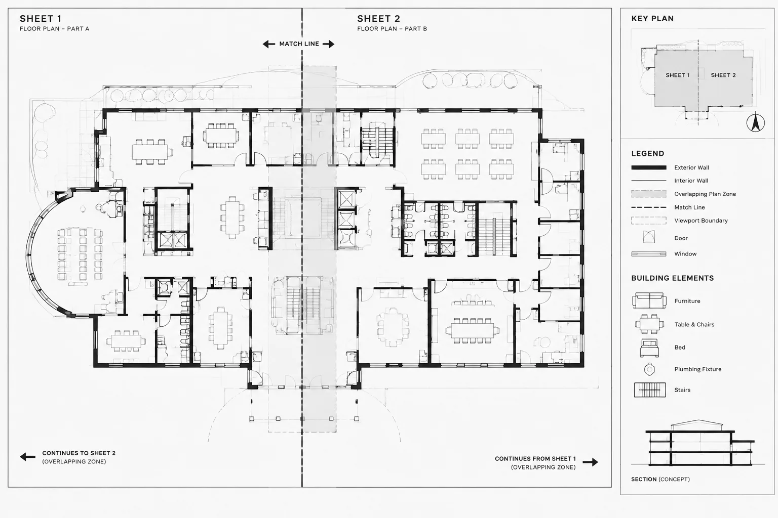
Splitting a large architectural plan is a sheet-organization task, not a reason to divide the building geometry into disconnected drawings. A successful layout lets readers move between partial plans without losing their position, while allowing the drafting team to coordinate changes from a shared source.
This guide covers the decisions behind effective match lines: where to divide the plan, how much contextual overlap to retain, how to reference the continuation, and how to manage viewports and annotation without creating conflicting information.
Large floor plans often cannot be shown clearly on a single sheet at the project’s chosen drawing scale. Reducing the plan may make dimensions, room tags, door numbers, and wall details difficult to read. A better solution is to divide the building into partial plan views and connect those views with architectural CAD match lines.
A match line is more than a graphic boundary. It tells the reader where a plan continues, identifies the related view or sheet, and helps the drafting team maintain continuity across separate drawings. If the split is poorly located or inconsistently managed, walls can appear to stop unexpectedly, dimensions may be repeated, and revisions can be missed on one side of the division.
This workflow explains how to divide a large plan while preserving one coordinated building model, clear sheet navigation, and dependable drawing output.
Start with One Coordinated Floor Plan
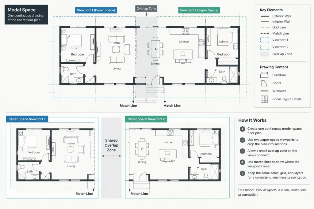
The safest approach is to maintain the complete floor plan as continuous geometry in model space. Partial plans should normally be presentation views of that shared plan rather than separate copies of the building.
Copying each wing or zone into an independent file may seem convenient, but it creates coordination risks. A wall moved in one copy may remain unchanged in another. Door tags, grids, room boundaries, and consultant backgrounds can also drift apart. Using viewports, clipped references, or other controlled viewing methods allows multiple sheets to display the same underlying geometry.
Before creating partial views, confirm that the base plan has:
- A verified drawing origin and unit setup
- Stable external-reference paths where references are used
- Consistent column grids and floor-level identifiers
- Coordinated room, door, and window numbering
- A defined sheet scale appropriate for the required information
- Layer organization that supports viewport-specific display control
Choose Logical Plan Divisions
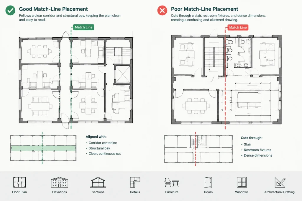
A match line should be placed where readers can easily understand how the two views connect. The shortest geometric split is not always the clearest drawing split.
Prefer recognizable building zones
Use major circulation paths, structural bays, building wings, expansion joints, courtyards, or other recognizable organizing features when practical. These elements help readers locate the continuation on the adjacent sheet.
Avoid cutting through dense information
Try not to place a division through stairs, elevators, restrooms, kitchens, complex millwork, equipment rooms, or crowded door groups. Splitting these areas can separate dimensions from the objects they control and make coordination with enlarged plans more difficult.
Do not treat the split as a construction joint
A drawing match line is a documentation device. It does not automatically indicate a physical joint, phase boundary, fire separation, property line, or material transition. If one of those conditions exists, show and label it independently according to the project’s documentation requirements.
Use an Overlap Zone Instead of a Hard Cut
Adjacent partial plans generally benefit from a modest overlap. The overlap provides visual context and allows the reader to confirm that corridors, grids, walls, and room sequences continue correctly.
The overlap should be large enough to show recognizable shared features without duplicating an excessive portion of the plan. Its appropriate extent depends on plan complexity, annotation density, scale, and office standards. Avoid adopting an arbitrary distance without reviewing the actual sheet composition.
Useful elements to include in the overlap may include:
- At least one shared grid line or another stable reference
- Continuous corridor or exterior wall geometry
- Room names or numbers needed for orientation
- Door openings near the plan division
- Key dimensions needed to understand continuity
- Section, elevation, or detail callouts close to the boundary
Overlap does not mean every annotation must appear twice. The goal is continuity, not duplication.
Place the Match-Line Graphic Carefully
The match-line symbol should be visually distinct from walls, grids, property lines, and hidden elements. Place it on a dedicated annotation layer so its visibility, lineweight, linetype, and plotting behavior can be controlled without changing building geometry.
A match line may be straight or stepped to follow a practical division between plan areas. Keep the path simple. An unnecessarily complex boundary is harder to compare between sheets and may create confusing pockets of duplicated or omitted information.
The line should be visible in the sheet view but should not conceal critical geometry. Background masks or wipeouts may improve legibility in limited locations, but they must be checked carefully because they can hide walls, dimensions, or symbols in plotted output.
Create Clear Continuation References
Each side of the split needs a direct reference to the corresponding plan view. The wording and graphic format should follow the project’s established callout convention. At minimum, the reader should be able to identify where the plan continues without searching through the entire drawing set.
A continuation label commonly communicates:
- That the drawing continues beyond the match line
- The identifying name or number of the adjacent plan area
- The sheet or view reference used by the drawing set
- The direction in which the referenced area lies
Orient labels for comfortable reading from the sheet’s normal viewing direction. If two plan areas are shown on the same sheet, reference the view as clearly as the sheet. A sheet number alone may not distinguish between multiple views.
Coordinate Viewports and Clipping Boundaries
In a paper-space workflow, create a viewport for each partial plan and align it to the same model-space coordinate system. Viewports should use the same scale unless there is a documented reason for a difference.
Do not align adjoining plans by eye. Use common grids, known geometry, or saved views to establish repeatable positions. Lock viewport display settings after alignment so incidental zooming does not change the published scale or crop.
Viewport clipping boundaries do not need to sit directly on top of the visible match line. The crop can extend beyond it to create the overlap zone. The match line explains the conceptual division, while the viewport boundary controls what appears on the sheet.
If external references are clipped in model space, review whether that clipping affects other sheets. A crop needed for one partial plan should not unintentionally remove information from another view. Sheet-specific viewport control is often safer than altering a shared reference solely for presentation.
Manage Annotation Across the Split
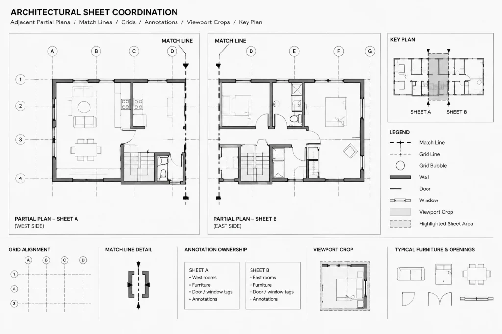
Annotation is usually the most difficult part of divided plans. A consistent ownership rule prevents duplicate or missing information.
| Drawing element | Recommended approach |
|---|---|
| Room tags | Show enough shared tags for orientation, but avoid competing duplicate tags in the overlap. |
| Dimensions | Assign each complete dimension string to one primary view where possible. |
| Door and window tags | Keep tags with the view that most clearly shows the opening and its surrounding context. |
| Grid bubbles | Maintain consistent grid identifiers and avoid unnecessary duplicate bubbles inside the overlap. |
| Section and elevation callouts | Confirm that references remain readable and point to the correct drawing after the plan is split. |
| General notes | Place view-specific notes with the responsible plan and set-wide notes in an appropriate common location. |
Avoid breaking a dimension string at the match line unless the documented condition genuinely requires separate dimensions. When a dimension must be repeated for orientation, verify that both instances report the same geometry and cannot be edited independently into disagreement.
Establish a Plan-Area Naming System
Large buildings may require several partial plans. Descriptive area identifiers are generally easier to coordinate than informal labels such as “left side” and “right side.” Names can relate to building wings, zones, quadrants, phases, or other stable project divisions.
Use the same area terminology in viewport titles, match-line labels, drawing indexes, issue notes, and team communication. If the building orientation changes on a sheet, directional names can become ambiguous. A key plan can resolve this by showing the entire building footprint and highlighting the area represented by each partial view.
Update Match Lines When the Plan Changes
Match lines should be reviewed whenever the building footprint, sheet scale, drawing scope, or annotation density changes. A division that worked during early design may later cut through a revised stair, tenant boundary, restroom group, or major equipment area.
When moving a match line, update both adjacent views as one coordinated task. Check the viewport crops, continuation labels, key plan, view titles, dimensions, tags, and callouts. Moving only the graphic line does not update the information controlled by the original split.
Quality-Control Checklist
Before issuing divided floor plans, compare the neighboring sheets side by side and verify the following:
- The same building geometry appears in the shared overlap
- No wall, opening, grid, or room is omitted between view crops
- Match-line labels point to the correct adjacent view and sheet
- Plan-area names agree with the drawing index and key plan
- Viewport scales, rotations, and layer states are intentional
- Dimensions are complete and are not misleadingly duplicated
- Door, window, room, and equipment tags remain coordinated
- Revision clouds and markers continue correctly across affected sheets
- Masks, wipeouts, and viewport boundaries do not hide required information
- The plotted PDF is readable at the intended output size
A final visual comparison is essential. Automated CAD checks may find missing references or layer problems, but they cannot fully judge whether a reader will understand where one partial plan ends and the next begins.
Build the Workflow Around Continuity
Effective architectural CAD match lines preserve the idea that the building is one coordinated plan, even when it must be presented on several sheets. Keep the base geometry continuous, divide the plan at recognizable locations, provide a useful overlap, and assign annotation deliberately. With clear continuation references and disciplined sheet checks, partial plans can remain easy to navigate throughout design, coordination, and construction documentation.
A Practical Way to Review the Finished Sheet Set
Review each partial plan first as an individual drawing and then as part of a connected sequence. The individual review confirms that the view is readable, while the sequence review reveals gaps, conflicting labels, inconsistent crops, and unclear transitions between sheets.
Begin at a recognizable feature near the match line and trace it into the adjacent plan. Follow walls, corridors, grids, openings, and nearby callouts as a reader would. If the continuation requires guesswork, improve the overlap, area identification, or reference label rather than relying on familiarity with the project.
Separate geometry control from presentation control
The building geometry, viewport crop, match-line graphic, and continuation label serve different purposes. Keeping these functions distinct makes revisions easier to diagnose. A missing wall may be a geometry or layer-display problem, while a missing area may result from the viewport crop. A confusing transition may instead be caused by the match-line annotation.
Check revisions across both views
A change near an overlap can affect more than the visible building elements. It may also alter dimensions, tags, callouts, masks, and the appropriate location of the match line. Treat neighboring partial plans as a coordinated pair whenever work occurs near their shared boundary.
Key principle: the reader should perceive one continuous building documented through several controlled views, not several separate plans that happen to resemble one another.
Frequently Asked Questions
What is the difference between a match line and a break line?
A match line identifies where a drawing continues in another plan view and normally includes a continuation reference. A break line indicates that part of an object or view has been omitted or shortened. Their graphics may vary by office convention, but their communication roles are different.
Should floor-plan geometry be trimmed at the match line?
Usually, the match line should not control or terminate the underlying building geometry. Keeping the plan continuous and using view-based cropping or display controls reduces the risk of gaps and conflicting copies.
Does a viewport boundary have to coincide with the match line?
No. The match line communicates the conceptual division to the reader, while the viewport boundary controls the displayed area. Extending the crop beyond the line can preserve useful context in the overlap.
Should annotations be duplicated in the overlap?
Only when duplication improves orientation without creating ambiguity. Assign important dimensions, tags, and notes to a primary view wherever practical, then use limited repeated information to help readers recognize the shared area.
When should a match line be relocated?
Reconsider its location when design changes, annotation growth, or sheet composition makes the existing division difficult to read. Moving it requires coordinated updates to both partial views and their associated references.
How can a key plan support split floor plans?
A key plan shows the relationship between each partial view and the overall building footprint. It is especially useful when area names, sheet orientation, or adjoining plan locations are not immediately obvious from the partial plan alone.