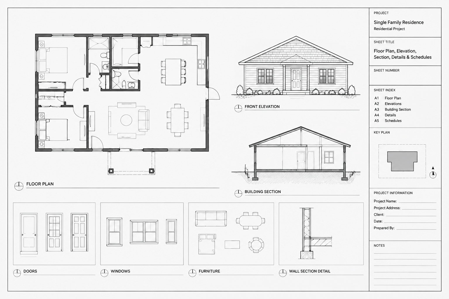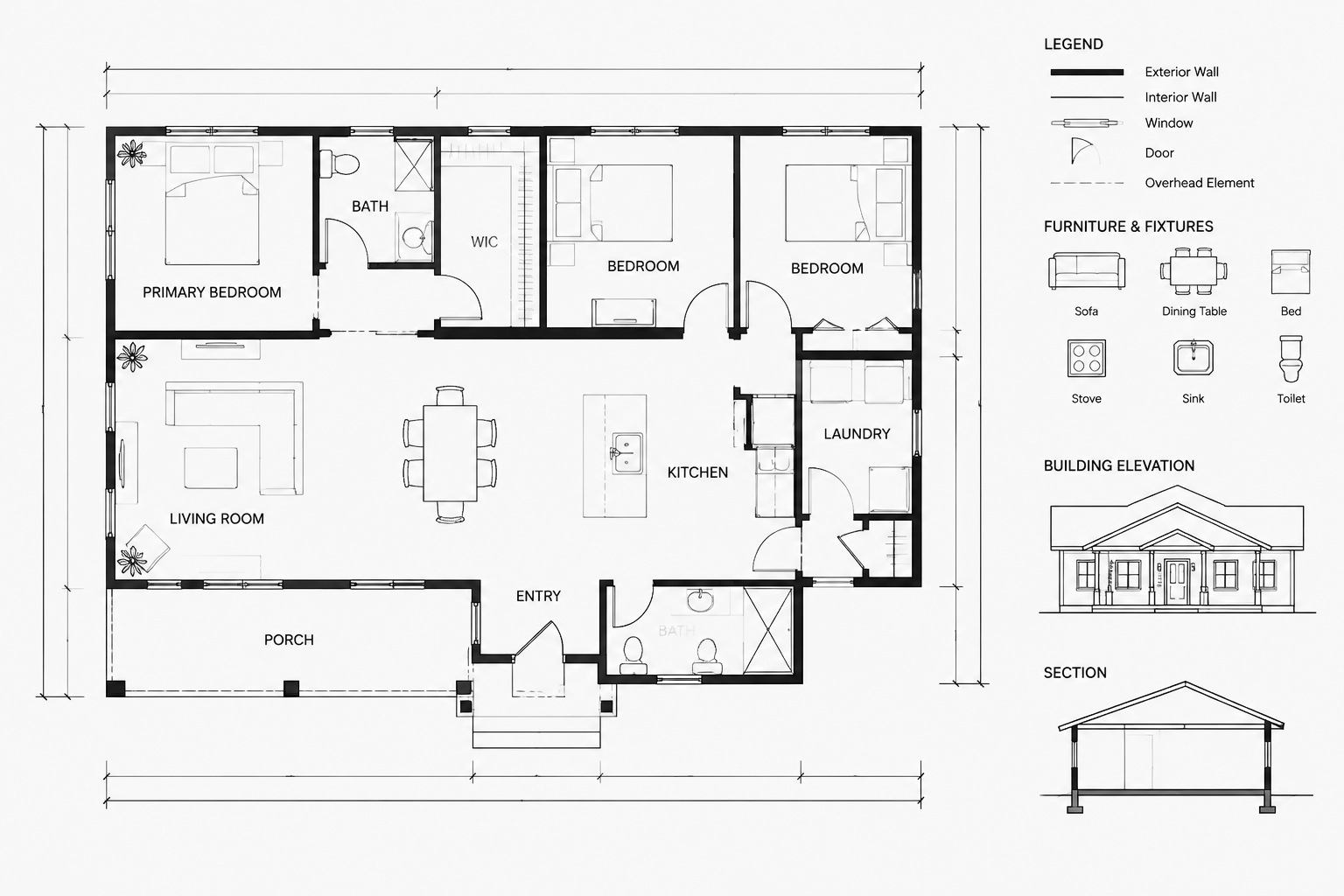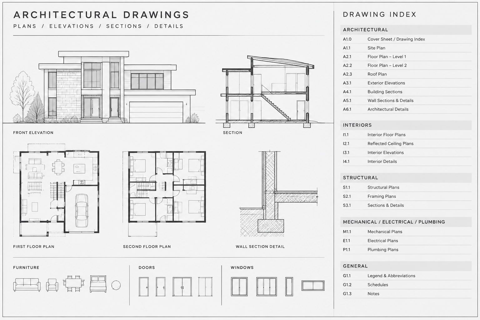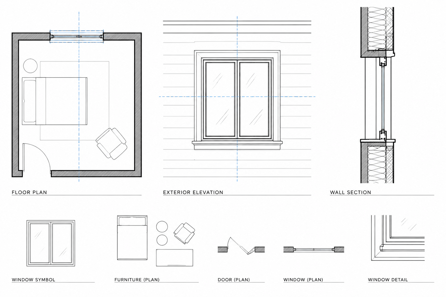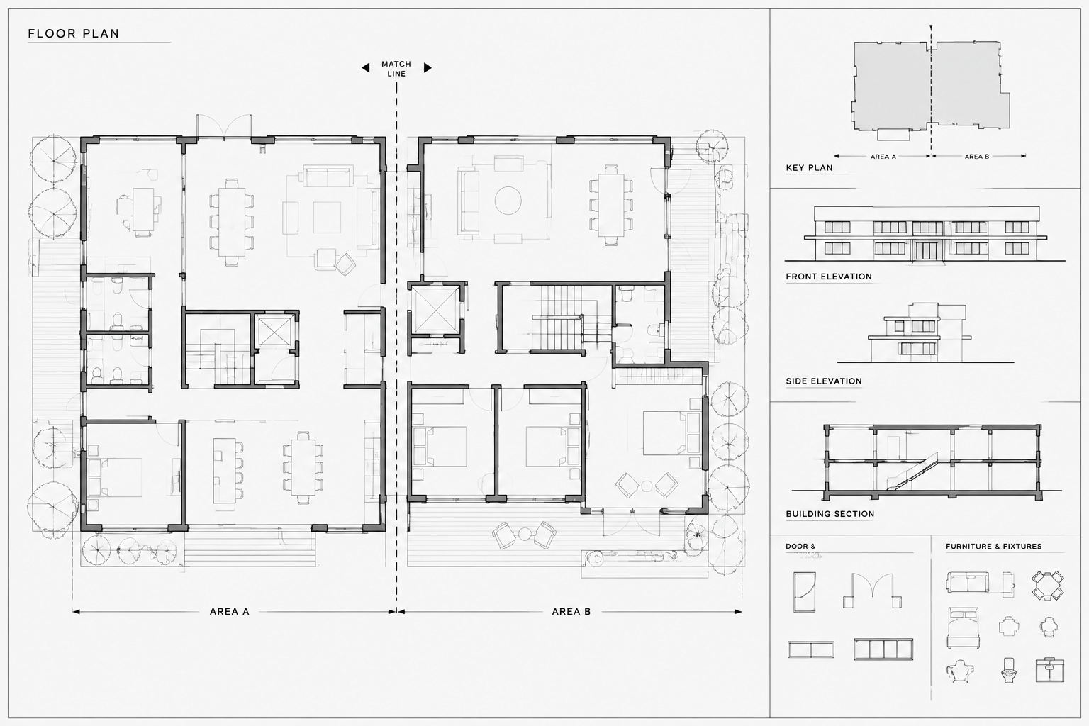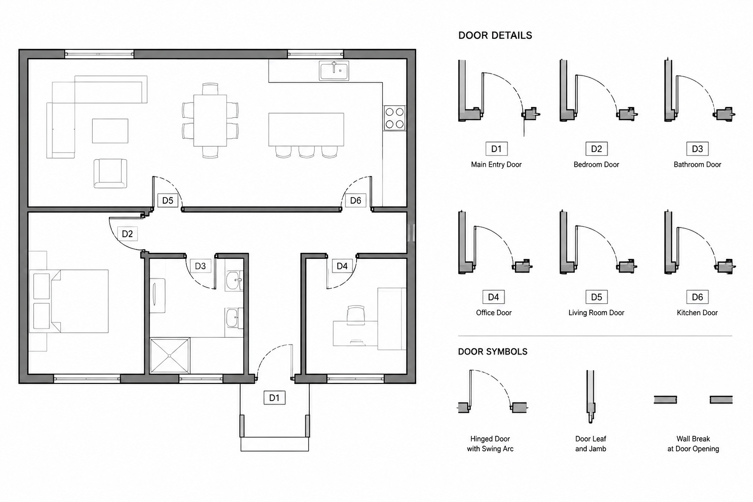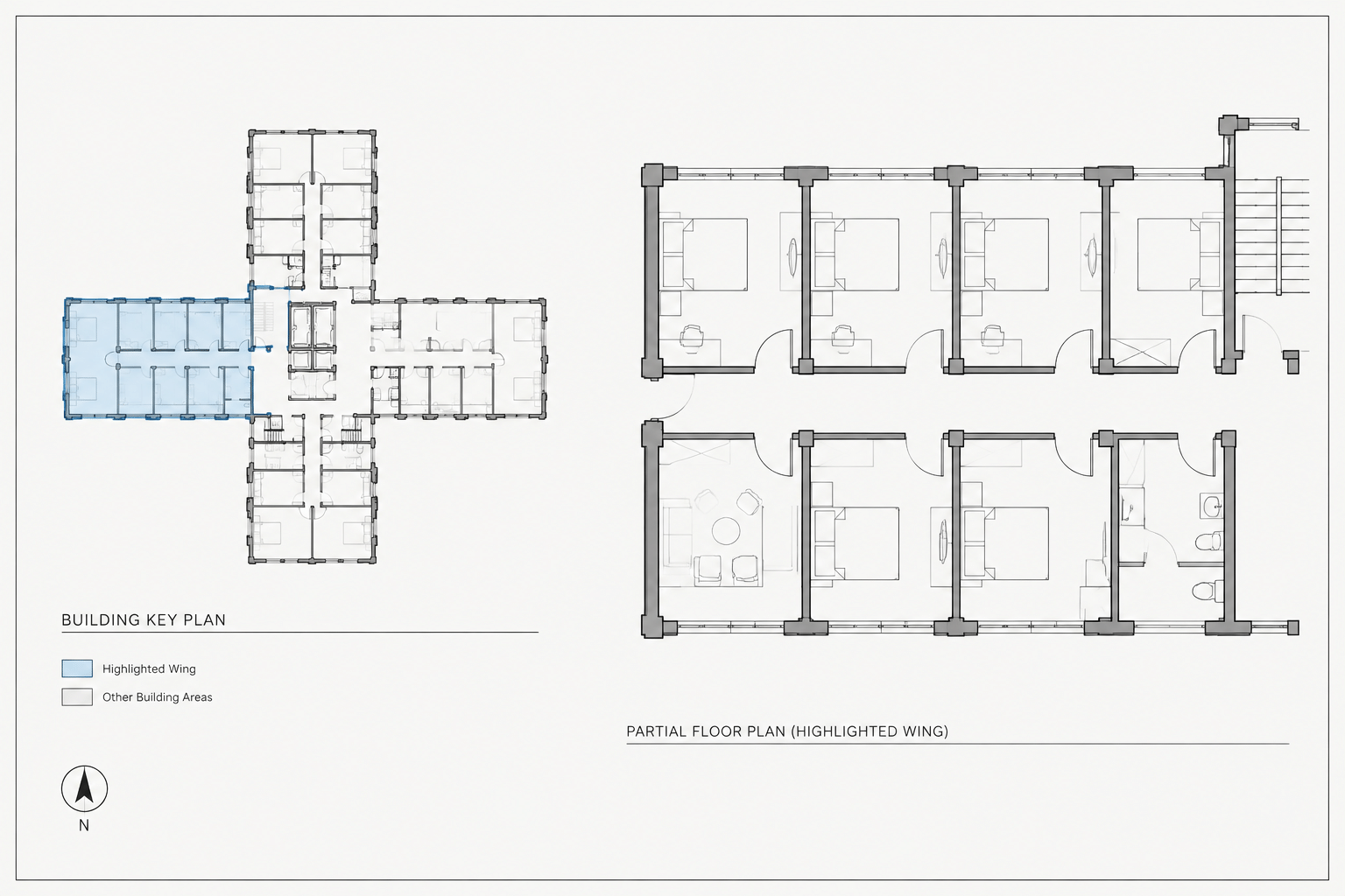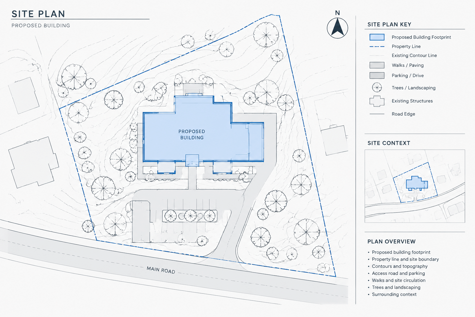
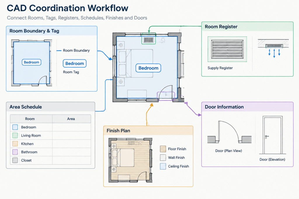
Room tags appear simple, but they often connect several parts of an architectural drawing set. A room name or number shown incorrectly on the floor plan can also affect finish plans, reflected ceiling plans, interior elevations, door schedules, signage information, and area summaries. For that reason, room tags should be treated as coordinated project data rather than isolated pieces of text.
A reliable workflow separates the visible room tag from the geometry used to calculate area. The tag communicates information to the reader, while a closed boundary defines the measurable region. Keeping those functions distinct makes it easier to revise layouts, check calculations, and control what appears on plotted sheets.
Decide What the Room Tag Needs to Communicate
Before building or placing tags, establish which information belongs in them. The answer depends on the drawing purpose and the office standard. A general floor plan may need only a room name and number, while a leasing plan or area plan may also display a calculated area. Finish information is often better placed in a separate finish tag or schedule rather than crowded into the primary room tag.
Common room-tag content includes:
- Room name
- Room number or identifier
- Calculated area when relevant to the sheet
- Finish references where the project workflow requires them
- Department, unit, zone, or occupancy description when useful
Avoid using the same visual hierarchy for every value. The room name and number usually need to be found quickly, while supporting data can be less prominent. Test the tag at its intended plotted scale rather than judging it only while zoomed in within model space.
Establish a Room-Numbering Logic Before Tagging
Room numbers should follow a project-wide system. The exact format can vary, but it needs to remain understandable as rooms are added, removed, or divided. Coordinate the numbering logic before extensive annotation begins, especially on projects with multiple levels, wings, tenant areas, or phases.
Renumbering a room is not just a plan edit. The same identifier may appear in door data, finish information, interior elevation references, equipment lists, and consultant documents. Maintain a simple room register or schedule that records the current room name and number. This provides a central review list and helps expose duplicates.
Do not assign permanent-looking numbers merely to fill unfinished plans. If planning is still fluid, use a clearly controlled preliminary method and replace it systematically when the project numbering structure is approved by the project team.
Create a Dedicated Area-Boundary Layer
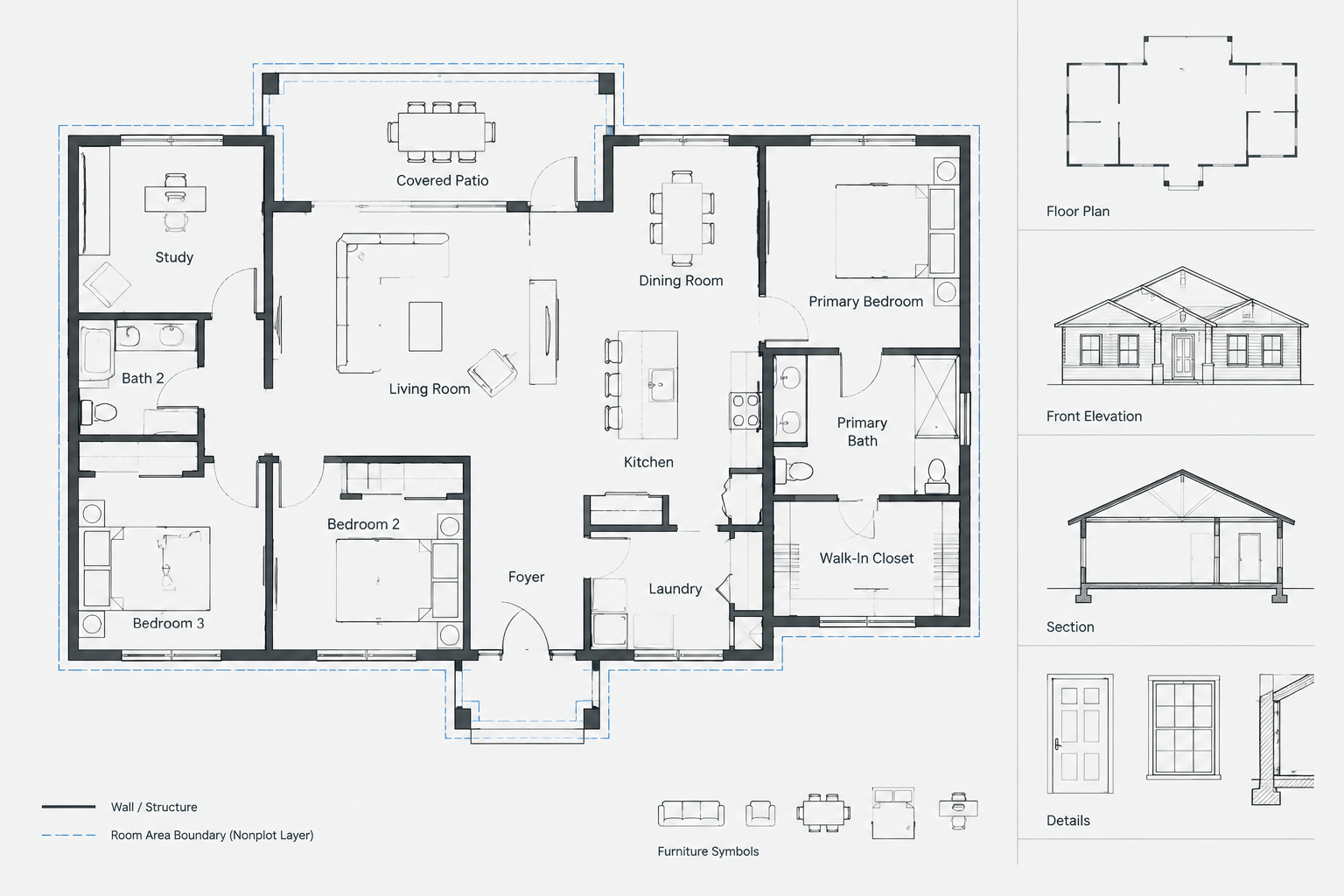
Area boundaries are working geometry and usually should not plot on the construction plan. Place them on a dedicated layer with a clear name, consistent color, and nonplot status where appropriate to the office CAD standard. Do not place boundaries on a general notes layer or hide them among wall lines.
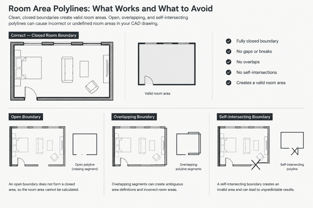
The boundary for each room should be a closed object rather than a collection of unrelated segments. Closed polylines are useful because they can be selected, checked, revised, and measured as single objects. They also make small gaps and overlaps easier to identify.
Keep boundary geometry independent from wall, door, casework, and hatch objects. Deriving an initial outline from nearby geometry may save time, but the resulting object should be cleaned before it becomes the room-area boundary. Door swings, trim lines, columns, cabinetry, and overlapping wall components can create unintended loops or fragments.
Define the Measurement Basis
Area can be measured to different reference lines, such as a wall face, centerline, lease line, or another project-defined boundary. These approaches do not produce interchangeable results. The correct method depends on the purpose of the drawing, contractual requirements, client instructions, and any standards governing the project.
Record the selected basis in the project drafting notes or CAD execution plan. Do not let individual drafters make room-by-room assumptions. If one room is measured to a finish face and another to a wall centerline, the resulting schedule may appear precise while being internally inconsistent.
Build Clean Boundaries from the Floor Plan
A practical room-boundary workflow is:
- Turn on the architectural layers needed to understand the enclosure.
- Reduce visual clutter by temporarily freezing unrelated furniture, annotation, ceiling, and equipment layers.
- Trace the required measurement line with a continuous polyline.
- Close the polyline and verify that the CAD application recognizes it as closed.
- Inspect recesses, columns, open connections, and wall offsets at a closer zoom.
- Place the finished boundary on the dedicated area layer.
- Calculate or extract the area only after the geometry has been checked.
Automatic boundary-generation tools can be helpful, but they should not replace inspection. Dense plans may contain tiny gaps, duplicate lines, nested outlines, or geometry imported from external references. A generated boundary can follow the wrong edge while still looking convincing at normal viewing scale.
Handle Open and Connected Spaces Deliberately
Open-plan spaces require a documented decision about where one room or functional area ends and another begins. A change in floor finish, ceiling treatment, furniture zone, departmental responsibility, or planning grid may suggest a boundary, but none should be assumed automatically.
When an area boundary crosses open space, keep the nonphysical division on the area layer rather than drawing a false wall. If readers need to understand the division, use an appropriate visible symbol, note, or area-plan graphic instead of relying on hidden calculation geometry.
Coordinate Tags with Their Boundaries
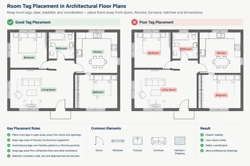
Place the tag inside the room it identifies whenever space permits. Its position should not imply that it belongs to an adjacent room, corridor, or open zone. Avoid placing tags over door swings, plumbing fixtures, dense hatch patterns, dimensions, or important furniture clearances.
Room names and numbers can be entered manually, but manual text increases the chance that the tag and area schedule will disagree. Where the office setup supports linked object properties, attributes, fields, or data extraction, consider using them to reduce repeated entry. Any linked workflow still requires quality control: a field can report the wrong object accurately if it was linked to the wrong boundary.
Use one defined source for each data item. For example, the room number should not be independently typed into the plan tag, finish schedule, and area table if the workflow provides a practical way to coordinate it.
| Drawing item | Recommended source | Coordination check |
|---|---|---|
| Room name | Room register or controlled tag data | Matches plan use and schedule wording |
| Room number | Project numbering register | Unique and consistent across sheets |
| Room area | Checked closed boundary | Uses the agreed measurement basis |
| Finish reference | Finish plan or finish schedule | Points to the current room identifier |
| Door room association | Door and room coordination process | Uses the intended room side and current number |
Prepare a Room and Area Schedule
A room schedule is useful even when it is not issued as a formal sheet table. It can function as an internal coordination tool that lists every room identifier, name, level, area, and relevant status. Sorting the list by room number helps reveal duplicates, missing entries, or identifiers assigned to more than one space.
Area totals should be assembled only from boundaries created for the same purpose and measurement basis. Do not combine room-level net areas, departmental boundaries, leasing areas, and overall building outlines without clearly defining how the categories relate. These values may overlap or exclude different portions of the plan.
Keep calculation precision separate from displayed precision. CAD geometry may retain more decimal detail than a drawing needs to show. Choose schedule and tag formatting according to the project requirements, but retain enough underlying accuracy to avoid introducing unnecessary rounding errors into totals.
Manage Changes Without Losing Coordination
Room boundaries should be reviewed whenever walls, partitions, shafts, columns, or major casework defining an area move. A visual plan comparison is not enough because a boundary can remain in its former location after the architectural geometry changes.
Use a repeatable revision sequence:
- Update the architectural plan geometry.
- Review every affected room boundary.
- Recalculate or refresh linked area values.
- Confirm room names and numbers.
- Update the room or area schedule.
- Check related finish, ceiling, door, and interior elevation drawings.
- Plot a coordination sheet and inspect tag legibility.
When a room is split, do not simply copy its original tag and change one number. Create and verify separate boundaries, establish the new room identities, and review every related schedule reference. When rooms are combined, remove obsolete boundaries and tags instead of leaving hidden duplicates in the file.
Common Problems and Their Causes
- Area reads as zero or cannot be calculated: The boundary may be open, self-intersecting, or composed of separate segments.
- Area changes unexpectedly: A boundary vertex may have moved, or the outline may include an unintended recess or adjacent space.
- Tag and schedule disagree: The values may have been entered independently or not refreshed after a revision.
- Duplicate room numbers appear: Numbering was assigned locally without checking the project register.
- Boundary lines plot on the sheet: The objects may be on the wrong layer or the area layer may not be configured as intended.
- Tags are difficult to read: Furniture, hatches, dimensions, or other annotation may be competing for the same space.
Final Quality-Control Checklist
Before issuing a plan or area study, isolate the room-tag and area-boundary layers for a focused review. Confirm that each included space has the intended tag, each tag corresponds to one controlled room identifier, and every reported area comes from a checked boundary. Then review the same information in the context of the complete plotted sheet.
A strong room-tag workflow is not defined by elaborate graphics. It is defined by consistent identifiers, defensible boundaries, controlled data sources, and disciplined revision checks. When those elements are organized, room information becomes easier to read and far less likely to conflict across the architectural drawing set.