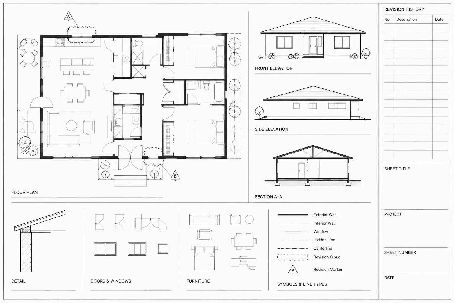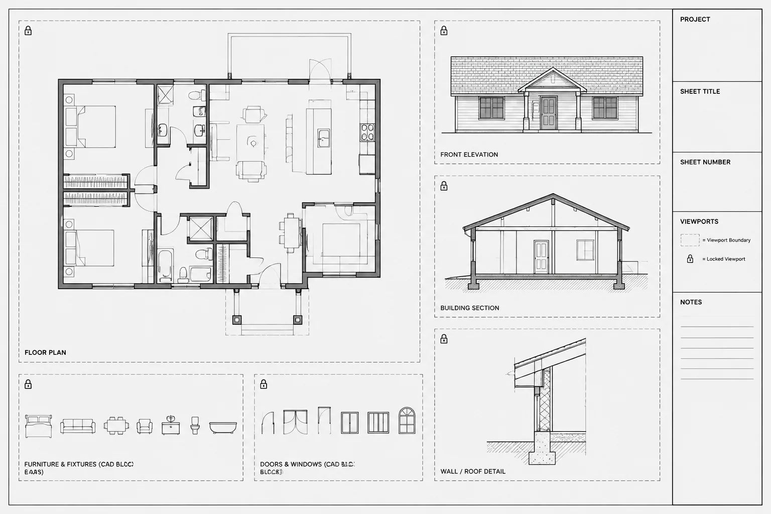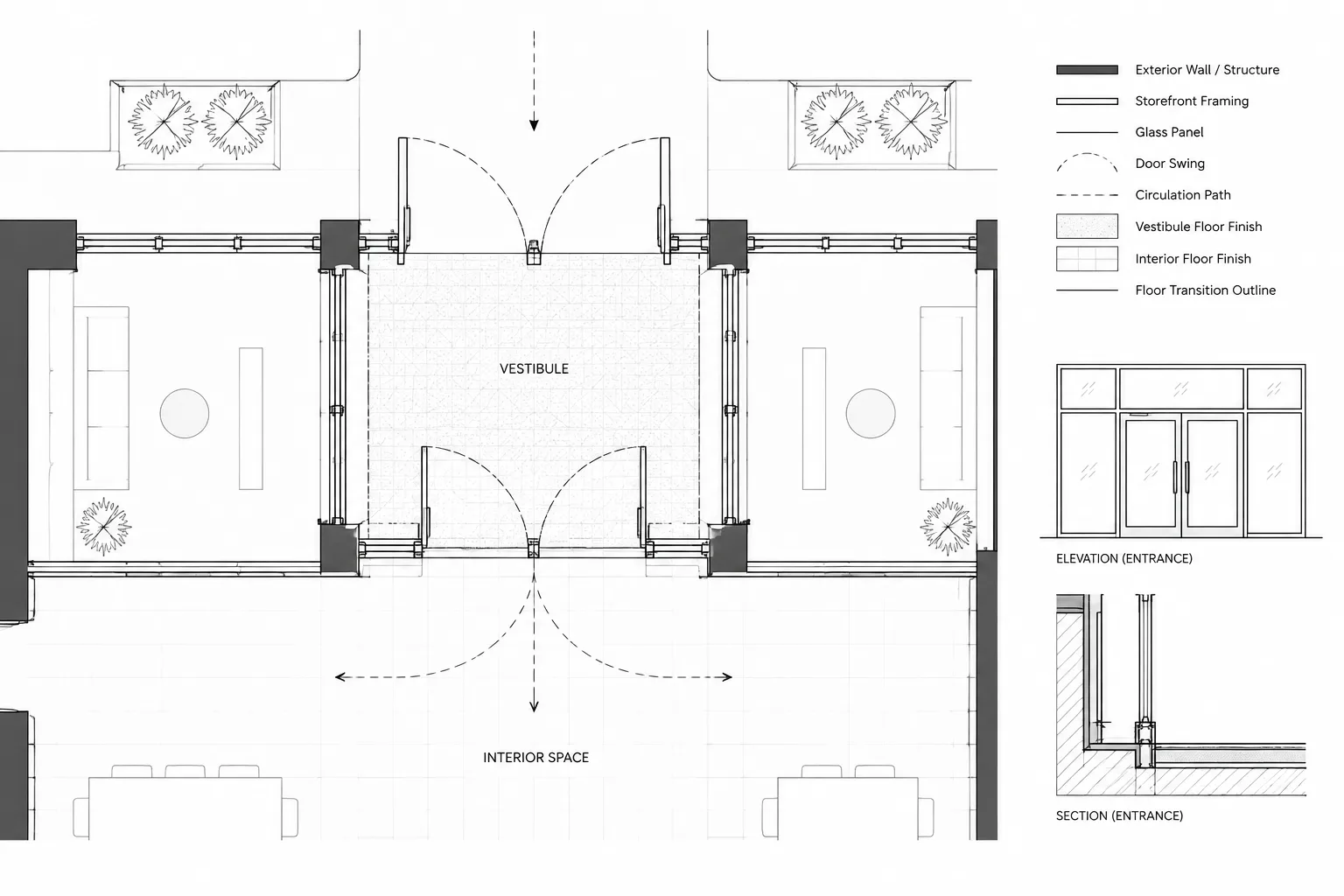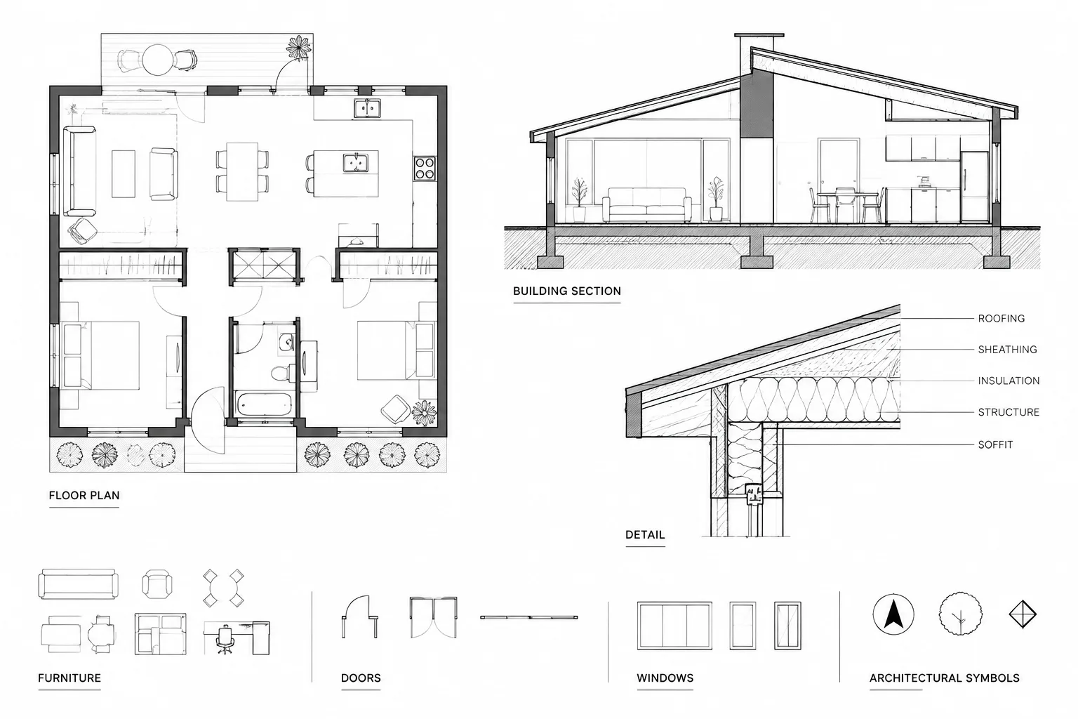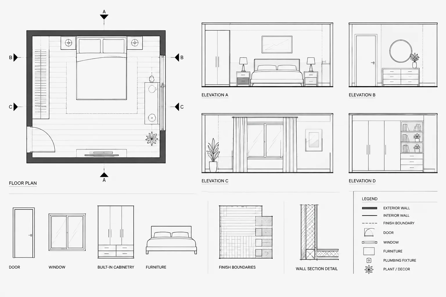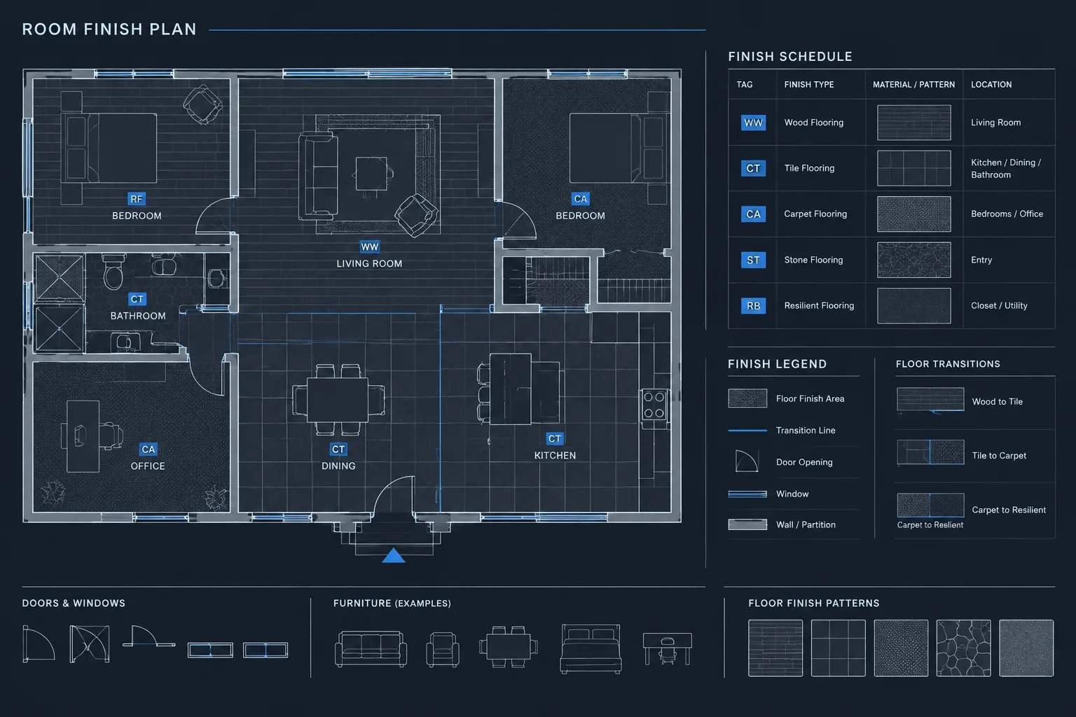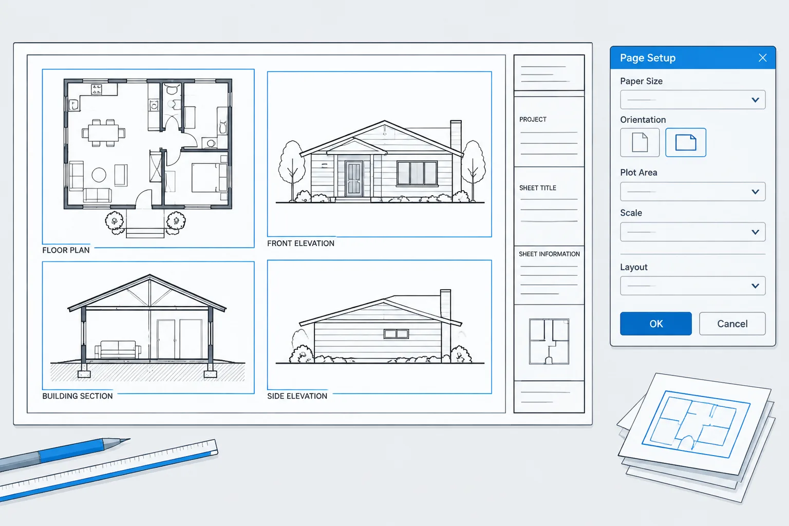
Consistent PDF output depends on more than a well-drafted sheet. The layout, page setup, viewport configuration, plot style, and output device must work as a coordinated system. A problem in any part of that system can affect sheet alignment, graphic hierarchy, or plotted scale.
The workflow below treats page setups as controlled project resources rather than personal plotting preferences. It also explains how to distinguish a sheet-output problem from a viewport or drawing-property problem before making changes.
A well-composed architectural sheet can still produce a poor PDF if its plotting settings are inconsistent. The wrong paper size, plot area, orientation, scale, plot style, or output device can create clipped title blocks, unexpected lineweights, and sheets that do not align when viewed as a set.
An AutoCAD page setup stores the principal plotting choices for a layout. Instead of configuring these options manually every time a sheet is issued, a project team can establish named page setups and apply them across related layouts. This reduces repetitive work and makes plotting errors easier to identify.
This guide explains a practical workflow for creating and maintaining an AutoCAD page setup for architectural drawings. Interface wording may vary by software release and office configuration, but the coordination principles remain the same.
What an AutoCAD Page Setup Controls
A page setup is a saved group of layout and plotting settings. It commonly controls:
- The selected printer, plotter, or PDF output configuration
- The available paper size
- Portrait or landscape orientation
- The portion of the drawing to plot
- Plot placement and centering
- The relationship between paper units and plotted output
- The assigned color-dependent or named plot style table
- Whether lineweights and other plot options are used
- Additional output properties supported by the selected device
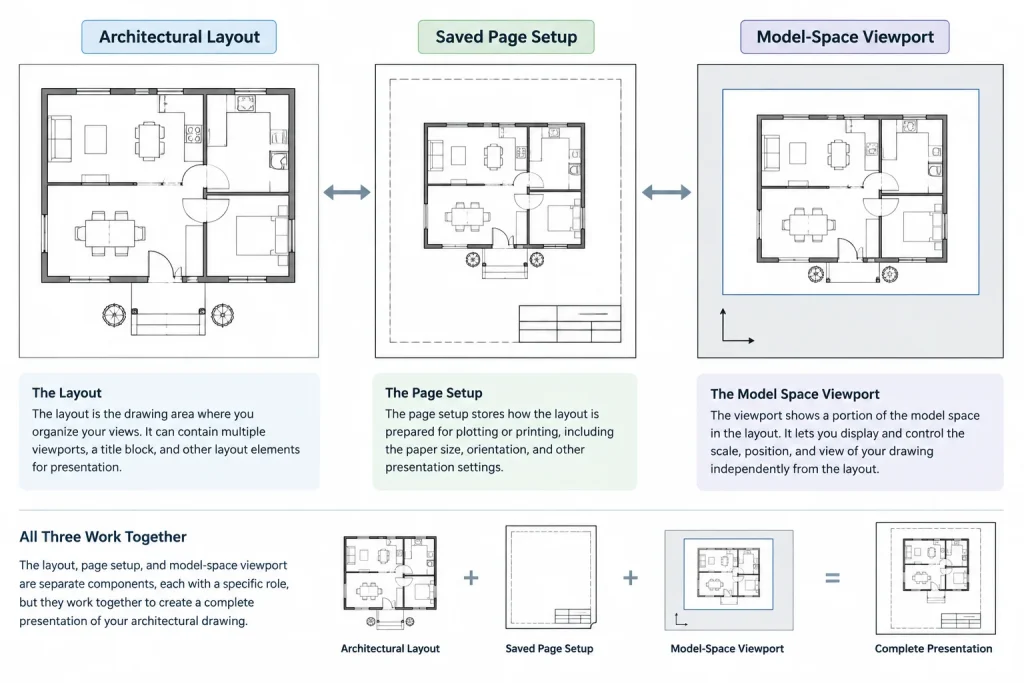
A page setup does not determine the scale of every model-space view shown on a sheet. In a typical paper-space workflow, the layout is plotted at paper size while each viewport controls the scale of its own model-space view.
Page Setup, Layout, and Viewport: Know the Difference
These three elements work together, but they perform different jobs:
| Element | Primary purpose | Typical contents or settings |
|---|---|---|
| Layout | Represents the drawing sheet in paper space | Title block, sheet notes, viewports, revision information, and sheet-specific annotation |
| Page setup | Defines how the layout is sent to a printer or file | Output device, paper size, plot area, orientation, plot style, and related options |
| Viewport | Displays a controlled view of model space on the sheet | View scale, view position, layer overrides, and visible model extent |
Keeping these responsibilities separate helps prevent a common mistake: changing the overall layout plot scale to correct a viewport-scale problem. If the title block fits the sheet but the plan appears too large or too small, inspect the viewport before changing the page setup.
Prepare the Layout Before Building the Page Setup
Begin with a layout that has a correctly sized title block and a clear paper-space organization. The title block should correspond to the intended sheet format rather than being stretched to fit a different page.
Check the following before editing plotting settings:
- The title block is drawn or inserted at its intended paper-space size.
- The layout is not carrying obsolete title blocks outside the printable sheet.
- Viewports are placed within the drawing area reserved by the title block.
- Paper-space notes and symbols use the project’s intended text and annotation system.
- The drawing uses the expected plot-style workflow.
If the office uses both color-dependent and named plot styles, do not select a table merely because its filename looks familiar. Confirm which system the drawing was created to use. A mismatch can produce incorrect lineweights or colors even when the rest of the page setup is correct.
Create a Named Page Setup
1. Start from the target layout
Open a representative sheet layout and access the page setup controls. Create a new named setup or modify a controlled project setup. Use a name that describes its purpose clearly, such as the output type, sheet format, and orientation. Avoid vague names like “New Setup” or “Final.”
2. Select the output device
Choose the printer, plotter, or PDF configuration used by the project. For digital issue sets, a managed PDF configuration generally provides more consistent results than relying on whatever physical printer happens to be connected to a workstation.
The output device matters because it determines which paper sizes and device-specific options are available. If a setup references a configuration that another user does not have, AutoCAD may substitute a device or flag the setup for correction.
3. Choose the matching paper size
Select the paper definition that matches the title block and intended issue format. Similar paper names may represent different printable areas or device definitions, so verify the sheet preview rather than relying on the name alone.
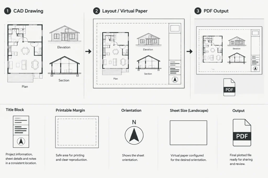
If the title block is clipped or shifted, first check the chosen paper definition and orientation. Do not immediately move or scale the title block to compensate for an incorrect setup.
4. Set the plot area to the layout
For a conventional paper-space sheet, plot the layout rather than selecting a temporary window around the title block. A window-based plot can work for one-time output, but it is vulnerable to inconsistent corners, offsets, and accidental omissions.
A layout-based plot creates a repeatable relationship between the virtual sheet and the output page. It also makes batch plotting more predictable.
5. Confirm plot scale and placement
The layout should ordinarily be output as a paper-space sheet, while the viewports carry the drawing-view scales. Review the plot placement and preview to confirm that the sheet aligns with the expected printable area.
Do not use a fit-to-paper option as a routine fix for an incorrectly sized title block. Fitting can introduce subtle scaling differences between sheets, which is especially problematic when someone prints the PDF and expects measured paper distances to correspond with the labeled drawing scale.
6. Assign the correct plot style
Select the project-approved plot style table and enable the associated plotting options required by the office workflow. The plot style translates drawing properties into plotted appearance, so an incorrect selection can flatten lineweight hierarchy or make screened information too dark.
Plot style assignment should be coordinated with object properties. Objects that carry arbitrary overrides may not respond as expected even when the page setup is correct.
7. Review additional output options
Inspect settings related to lineweights, transparency, shading, and output quality where they apply. More output processing is not automatically better. Enable options because the drawing requires them, not because they are available.
Complex transparency, dense hatches, raster references, and shaded viewport content can affect PDF appearance and performance. Test a representative sheet before applying the setup to an entire project.
Use Plot Preview as a Technical Check
Plot preview is more than a final visual glance. It is an opportunity to verify the interaction of the layout, page setup, title block, viewports, and plot styles.
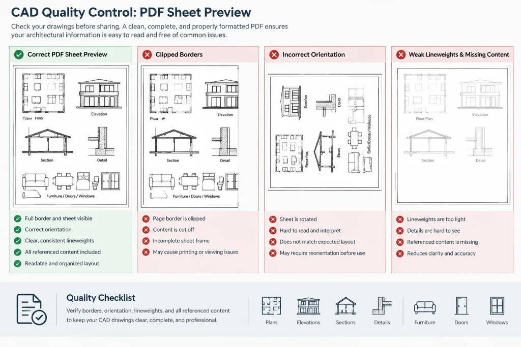
Check the preview for:
- Clipped sheet borders, notes, or revision information
- Unexpected blank margins or an off-center sheet
- Incorrect portrait or landscape orientation
- Missing lineweights or excessive graphic weight
- Hatches that merge into solid dark areas
- Screened or background information plotting too strongly
- Viewport frames that should not appear in the issued drawing
- Images, underlays, or referenced files that are absent
After creating the PDF, inspect the file itself. A correct preview does not replace reviewing the deliverable, especially when the sheet contains external references, raster content, transparency, or unusual fonts.
Apply the Setup Across Multiple Layouts
Once a representative sheet plots correctly, apply the named page setup to layouts that use the same output conditions. Do not assume every layout in a project uses the same format or orientation. Detail sheets, presentation sheets, permit sheets, and consultant inserts may require different controlled setups.
A practical project might maintain a small family of setups rather than one universal option. Names should make the differences obvious. Keep the list limited to configurations the team actually uses; duplicate or obsolete setups make the wrong selection more likely.
When publishing or batch plotting, confirm that each layout references the intended setup. A successful single-sheet test does not prove that all other layouts are configured correctly.
Importing Page Setups from a Template or Controlled Drawing
Page setups can be brought into project drawings from a trusted template or source drawing. This is useful when existing files were created without the current office plotting configuration.
Importing a setup transfers saved plotting choices, but it does not repair the sheet automatically. The destination drawing may still have a differently sized title block, incompatible plot-style behavior, unusual paper-space geometry, or missing device configuration. Apply the imported setup and then review the preview and resulting PDF.
Use a maintained template as the source rather than copying setups from an arbitrary completed project. Old project files often contain outdated printers, redundant setup names, and temporary plotting experiments.
Common Page Setup Problems
The title block is clipped
Check the paper definition, orientation, plot area, and printable margin before editing title-block geometry. Also confirm that the title block was created for the selected sheet format.
The sheet plots at the wrong size
Determine whether the problem affects the entire paper-space layout or only a model-space view. Correct the page setup if the whole sheet is scaled. Correct the viewport if the title block is right but the drawing view is wrong.
Lineweights look incorrect
Verify the plot-style system, selected plot-style table, lineweight plotting option, layer properties, and object overrides. The page setup may be correct while individual objects bypass the expected layer-based properties.
Another user cannot plot the sheet
The drawing may reference a device configuration, plot-style file, font, or other support file that is unavailable on the second workstation. Compare support-file access and output configurations instead of repeatedly redefining the layout.
Batch output differs from manual output
Confirm that the batch process is using the saved layout page setups rather than temporary settings from a manual plot. Check every layout assignment, not only the active sheet.
Page Setup Quality-Control Checklist
- Use descriptive, controlled page setup names.
- Match the output device and paper definition to the intended title block.
- Plot paper-space sheets by layout rather than by an improvised window.
- Keep sheet output settings separate from viewport-scale settings.
- Assign the correct plot-style system and table.
- Review lineweights, screening, hatches, images, and transparency.
- Test a representative PDF before publishing the full set.
- Inspect the final PDF, not only the AutoCAD preview.
- Remove or clearly identify obsolete project setups.
- Verify setup assignments again before a formal issue.
A Repeatable Plotting Workflow
A reliable page setup turns plotting from a series of personal choices into a controlled project process. The strongest workflow begins with a correctly constructed layout, uses a named setup from a maintained source, tests the result on a representative sheet, and then applies the verified configuration across compatible layouts.
Page setups cannot correct poor viewport management, incorrect title-block sizing, missing references, or uncontrolled object properties. They can, however, provide a stable output foundation. When layouts, viewports, plot styles, and page setups each have a clearly defined role, architectural PDF sets become easier to produce, review, and reproduce across the project team.
Diagnose Plotting Problems in the Right Order
When a PDF looks wrong, avoid changing several settings at once. A controlled diagnostic sequence helps identify whether the issue originates in the sheet definition, the drawing view, or the plotted graphics.
- Check the full sheet first. Confirm that the title block, orientation, plot area, and paper definition agree. If the entire sheet is shifted, clipped, or scaled, investigate the page setup.
- Check each drawing view next. If the title block is correct but a plan, section, or elevation is the wrong size or position, inspect the viewport.
- Check graphic behavior separately. If geometry is positioned correctly but lineweights, screening, hatches, or colors are wrong, review the plot style, layer properties, and object overrides.
- Check referenced content. Missing images, underlays, fonts, or external references may indicate a file-access or support-file problem rather than a page setup error.
- Review the exported PDF. Confirm that the deliverable matches the preview and that PDF viewing or downstream printing settings are not introducing another change.
Manage Page Setups as Project Standards
A named setup is most useful when its purpose and ownership are clear. Teams should know which source drawing or template contains the approved configurations, which layouts use each configuration, and who is responsible for updating them when the output workflow changes.
Avoid creating a new setup for every plotting attempt. First determine whether an approved setup already matches the sheet. If a new configuration is necessary, give it a descriptive name, test it on representative content, and remove temporary alternatives after the result is verified.
Separate Authoring Checks from Issue Checks
During drawing production, previewing helps detect obvious layout and graphic problems. Before an issue, the review should also consider the complete sheet set. Confirm that related sheets share the intended output conditions, that exceptions are deliberate, and that the exported files appear in the expected sequence and orientation.
This separation is important because an individual sheet can plot correctly while the assembled set remains inconsistent. Page setup control is therefore both a drawing-level task and a document-set quality-control task.
Frequently Asked Questions
Does an AutoCAD page setup control viewport scale?
No. The page setup controls how the paper-space layout is output. Each viewport controls the scale and position of its model-space view. If the title block plots correctly but the drawing view does not, inspect the viewport before changing the page setup.
Why does the same drawing plot differently on another workstation?
The other workstation may not have access to the same output-device configuration, plot-style file, font, or related support resource. Compare the available project plotting resources before redefining the layout.
Should a title block be resized to match the selected paper definition?
Not as a routine correction. First verify that the selected paper definition, orientation, and plot area match the title block’s intended format. Scaling the title block to hide a setup mismatch can create inconsistent sheets.
Can one named page setup be used for every layout?
Only layouts with compatible output requirements should share a setup. Different sheet formats, orientations, or issue conditions may require separate controlled setups.
Why can a plot preview look correct while the PDF has problems?
The final file may expose issues involving referenced content, raster images, transparency, fonts, or output processing. Preview the sheet, export it, and then inspect the actual PDF that will be issued.
What should be checked when lineweights are wrong?
Review the drawing’s plot-style system, the assigned plot-style table, lineweight plotting options, layer properties, and object-level overrides. Incorrect graphics do not always mean the page setup itself is wrong.