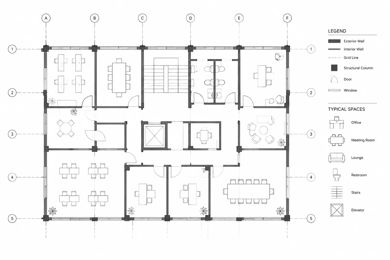
Column grids in architectural CAD connect structural locations with the plans, sections, elevations, dimensions, and consultant backgrounds that depend on them. Because the same axes appear throughout a drawing set, even a minor drafting inconsistency can create uncertainty about which geometry controls.
This guide presents a practical workflow for establishing grid ownership, drawing accurate axes, managing bubbles and labels, coordinating irregular systems, and checking revisions. Use it as a drafting and quality-control reference, while following the project team’s documented CAD standards and coordination responsibilities.
Column grids provide a shared reference system for locating structural supports, walls, openings, equipment, and major building elements. Although they appear simple, poorly managed grids can create widespread coordination problems. A shifted grid line, duplicated label, or inconsistent grid extent may affect plans, sections, elevations, details, and consultant files.
A dependable grid workflow begins by treating the grid as controlled project geometry rather than decorative annotation. Its location, naming, ownership, and presentation should remain consistent throughout the drawing set. The following workflow explains how to create and manage column grids in architectural CAD without confusing the structural layout or cluttering sheets.
Understand What the Grid Represents
A column grid is a series of reference axes used to identify locations in a building. A grid line may pass through the center of a column, align with a structural framing line, or establish another project-specific reference agreed upon by the design team. Do not assume that every column is centered on a grid or that every grid corresponds to a physical object.
The grid is also not a substitute for dimensions. Grid labels identify axes, while dimensions communicate measurable relationships. A drawing may need both, especially where walls, slab edges, or columns are offset from the primary structural axes.
Establish Grid Ownership Before Drafting
Determine which discipline controls the official grid geometry. On many projects, the structural drawings govern structural grid locations, but project responsibilities can vary. The architectural team may establish an initial planning grid before a structural model or background is available.
Record the agreed source and update process. If both architectural and structural files contain independently editable grids, small differences can develop without being obvious. A safer arrangement is to maintain one coordinated source and reference it where practical. If the architecture file must contain its own grid objects, include grid comparison in every major coordination review.
Build the Grid from Reliable Geometry
Start with axes, not bubbles
Draw the actual grid axes first. Use construction geometry, reference lines, or polylines according to the project’s CAD standards. Confirm that parallel grids are truly parallel and that perpendicular systems intersect cleanly. Avoid placing lines by eye or tracing over a visually similar PDF without verifying its scale and alignment.
For orthogonal buildings, use object snaps and controlled offsets to preserve exact relationships. For angled or curved building portions, define the governing geometry deliberately. A rotated wing may need its own named grid series rather than extensions that imply a false relationship with the main building.
Keep grid bubbles separate from grid axes
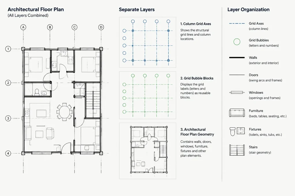
Grid bubbles are annotation attached to the reference system. They should not control the location of the axes. A practical CAD setup uses a block for the bubble and label, while the axis remains linework with appropriate layer and linetype properties.
An attributed block can make labels easier to edit and audit. Set the insertion point where the bubble meets the grid line so the symbol can be aligned precisely. If bubbles must be resized for different sheet scales, use an established annotation workflow rather than manually stretching individual symbols.
Create a Clear Labeling Sequence
Choose a labeling sequence that can be expanded without creating ambiguity. One direction may use numbers and the other letters, but the exact convention should follow the project’s established practice. Avoid labels that are easily confused when printed or viewed at low resolution.
When a new axis is inserted between existing grids, do not casually renumber the entire building. Renumbering can break references in details, calculations, consultant drawings, meeting notes, and field documents. Supplemental labels or another documented project convention may be safer, but the full team should agree before the change is issued.
Check every label for the following:
- Each axis has a unique identifier.
- The sequence follows a predictable direction.
- Labels match between architectural and structural drawings.
- Opposite ends of the same axis carry the same identifier.
- Renamed or deleted grids have been removed from dependent views.
Organize Grid Objects with Layers
Place grid axes and grid bubbles on clearly defined layers. Some offices keep both components together, while others separate axis linework from symbols and text. Separation can help when a viewport needs grid lines but not every bubble, or when graphic properties differ.
Use ByLayer properties unless the project has a specific reason for an override. Object-level colors, linetypes, and lineweights make global corrections more difficult. Grid layers should also be easy to identify in consultant backgrounds so recipients can freeze or display them as needed.
| Grid component | CAD concern | Coordination question |
|---|---|---|
| Axis line | Exact location, linetype, and extent | Does it match the controlling grid source? |
| Grid bubble | Block insertion, scale, and orientation | Is the label readable and connected to the correct axis? |
| Grid label | Attribute value and text style | Is the identifier unique and consistent across views? |
| Grid dimension | Associativity and witness points | Is it measuring the actual axes rather than nearby objects? |
Control Grid Extents for Different Views
Model-space grid lines often extend farther than needed for a particular sheet. Do not repeatedly trim the master grid to suit individual viewports. That can damage other views and make later revisions harder to manage.
Instead, plan how grids will appear at each drawing scale. Viewport clipping, layer control, or separate presentation linework may be appropriate depending on the office workflow. If separate presentation objects are used, clearly distinguish them from the controlling axes so they cannot drift unnoticed.
Grid bubbles should remain outside the building geometry where possible, with enough space for dimensions, section marks, match lines, and other annotations. Review actual sheet viewports rather than judging spacing only in model space.
Coordinate Grids Across Plans, Sections, and Elevations
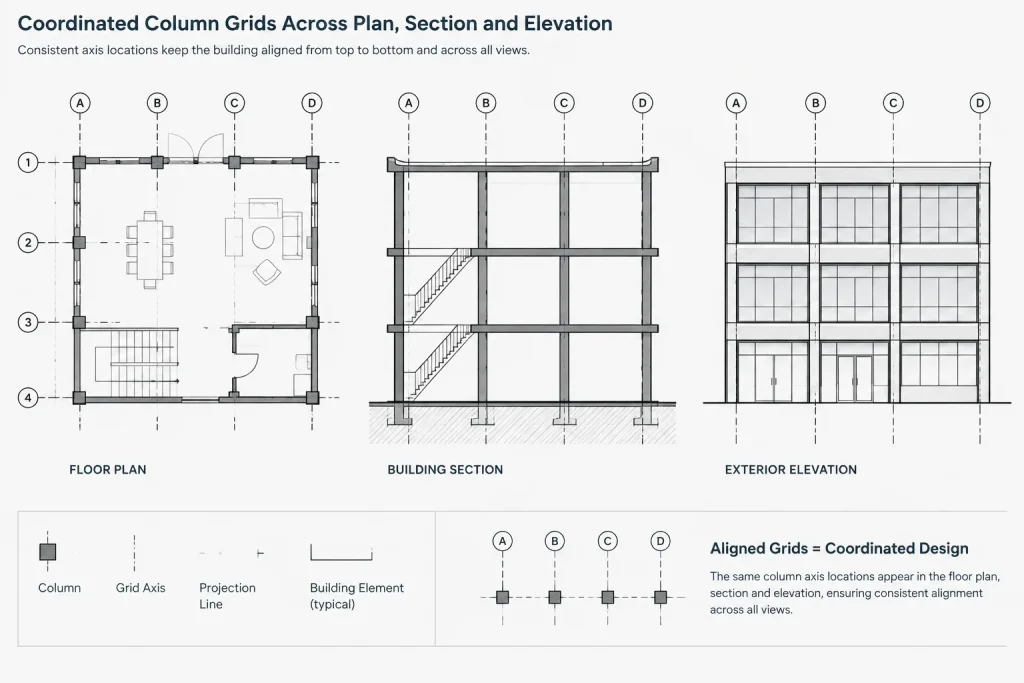
The same grid identifier should refer to the same axis everywhere. In sections and elevations, vertical grid lines help connect the view to the plan and clarify which structural bays are shown. Their horizontal placement should derive from the plan geometry rather than being recreated approximately.
When producing a section or elevation, project grid locations from a coordinated plan or use referenced geometry. Confirm that mirrored views, rotated views, and drawing direction have not reversed the apparent sequence incorrectly. A valid grid sequence may read differently from one side of a building, but each bubble must still identify the correct physical axis.
Handle Multiple and Irregular Grid Systems
Large buildings may include a main orthogonal system, a rotated wing, a radial portion, or a secondary framing layout. Trying to force all areas into one uninterrupted sequence can make the drawings harder to understand.
For each secondary system, clarify:
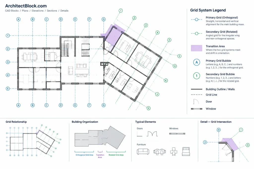
- Where the system begins and ends.
- How its labels differ from the primary grid.
- Whether axes intersect or remain independent.
- Which system controls shared transition areas.
- How the system appears in partial plans and key plans.
Irregular grids need especially careful dimensioning. An angled line may be accurately drawn but still difficult to reconstruct from the issued documents unless its relationships are communicated clearly.
Manage Grids in Existing Buildings
Existing structures may not follow a clean or perfectly regular grid. Field-surveyed column centers, historic drawing grids, and proposed planning axes can all differ. Do not adjust existing geometry merely to make the grid look more orderly.
Clearly distinguish verified existing axes from proposed reference systems. If record drawings are being used, treat their grid locations as reference information until they are checked against reliable survey or field data. Notes and layer naming should make the source and status understandable to other CAD users.
Run a Grid Quality-Control Review
Complete a dedicated grid check before issuing drawings or exporting consultant backgrounds. Freeze unrelated layers and inspect the grid system by itself. Then compare it with columns, bearing elements, major walls, plans, sections, and elevations.
- Look for duplicate or nearly overlapping grid lines.
- Confirm that every bubble is attached to the intended axis.
- Compare label sequences across all floor plans.
- Check that dimensions snap to grid geometry.
- Review rotated and partial plans for missing axes.
- Verify that demolished or abandoned grids are not presented as current work.
- Plot representative sheets to evaluate bubble size, lineweight, and annotation conflicts.
- Compare the architectural grid with the latest coordinated structural background.
Treat the Grid as Shared Project Infrastructure
A well-managed column grid makes a drawing set easier to navigate, coordinate, and revise. Its value comes from consistency: exact geometry, stable labels, clear graphic treatment, and controlled updates across disciplines.
Build the system from verified axes, keep annotation connected to the geometry, and avoid independent copies wherever possible. When a grid changes, review every dependent plan, section, elevation, detail reference, and consultant background. That disciplined approach prevents a small drafting change from becoming a project-wide coordination error.
A Practical Framework for Managing Grid Information
It is useful to think of a column grid as three connected parts: controlled geometry, axis identity, and sheet presentation. Controlled geometry establishes the actual location of each axis. Axis identity assigns a stable reference to that geometry. Sheet presentation determines how lines and bubbles appear in each plan, section, elevation, or partial view.
Keeping these functions distinct makes troubleshooting easier. A bubble can be moved to improve readability without changing the axis. A viewport can show a shorter grid extent without altering the project reference. A label can be corrected without redrawing the underlying geometry, provided the correction is coordinated across every dependent view.
Document Grid Changes Before Updating Sheets
When an axis is added, removed, shifted, or renamed, identify the reason for the change and the file that controls it before editing dependent drawings. Update the controlling source first, then review referenced backgrounds, dimensions, annotations, sections, elevations, details, and consultant exchanges affected by that axis.
A concise grid change record can help the team distinguish an intentional revision from an accidental mismatch. Record the affected axis, the nature of the change, the controlling source, and the drawings reviewed. This is especially valuable when several disciplines receive backgrounds at different stages of development.
Separate Geometry Checks from Graphic Checks
Grid quality control is more reliable when geometric accuracy and sheet appearance are reviewed separately. First isolate the grid and confirm axis locations, intersections, labels, and relationships to structural elements. Then inspect plotted or published views for bubble placement, line visibility, clipping, overlaps, and conflicts with other annotation.
This separation prevents a visually clean sheet from hiding inaccurate geometry. It also prevents correct model-space axes from being presented poorly in a viewport. Both conditions matter, but they require different corrections.
Use Grid References Carefully During Coordination
A grid label identifies an axis; it does not by itself prove that a wall, column, opening, or equipment item is centered on that axis. When an element is offset, the drawing should communicate that relationship with appropriate dimensions or other coordinated information rather than relying on visual proximity.
Before using a consultant grid as a drafting base, confirm its origin, orientation, status, and relationship to the current architectural background. Avoid moving referenced geometry simply to make files appear aligned. An unexplained alignment correction can conceal a genuine coordination problem that should be resolved by the responsible project team.
Frequently Asked Questions
Should grid bubbles and axis lines be part of the same CAD object?
They may be connected through an office-approved block or annotation workflow, but the bubble should not determine the axis location. The reference line remains the controlling geometry, while the bubble communicates its identifier on the drawing.
Should every column be centered on a grid intersection?
No. A project grid may represent structural centerlines or another agreed reference, and individual elements can be offset. Confirm the intended relationship from coordinated project information rather than assuming alignment from appearance alone.
Can architectural and structural files contain separate editable grids?
They can, but independent copies require deliberate comparison because they may drift apart. The team should identify the controlling source and include grid comparison in coordination reviews whenever separate grid geometry is maintained.
How should grids be shown in partial plans?
Show the axes needed to locate and understand the partial view while preserving the identifiers used in the overall project system. Check that clipping, match lines, and annotation do not hide required bubbles or suggest that a continuing axis has ended.
What should be checked after a grid is renamed?
Review opposite-end bubbles, plans, sections, elevations, dimensions, detail references, partial views, consultant backgrounds, and other documents that refer to the previous identifier. A label change should be treated as a coordinated project revision rather than an isolated text edit.
Why should grid dimensions snap directly to axes?
Snapping to the actual axis geometry reduces the risk of dimensioning a nearby wall, column edge, bubble, or presentation line by mistake. The dimension should report the intended reference relationship, not merely a visually similar location.