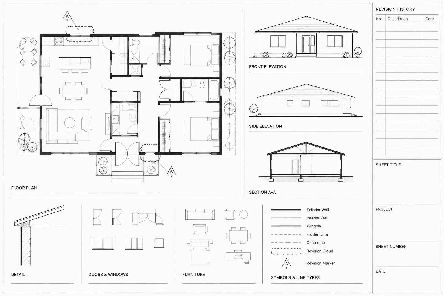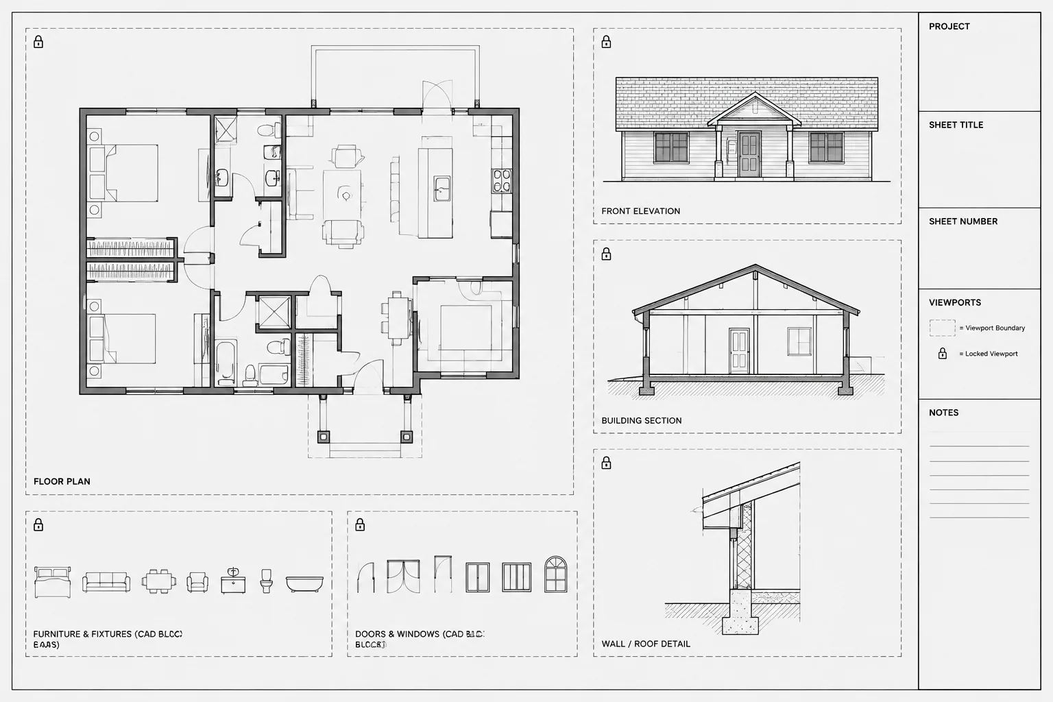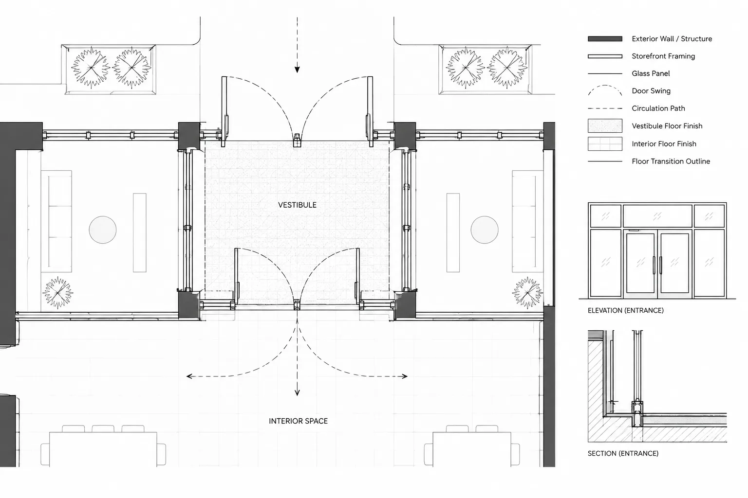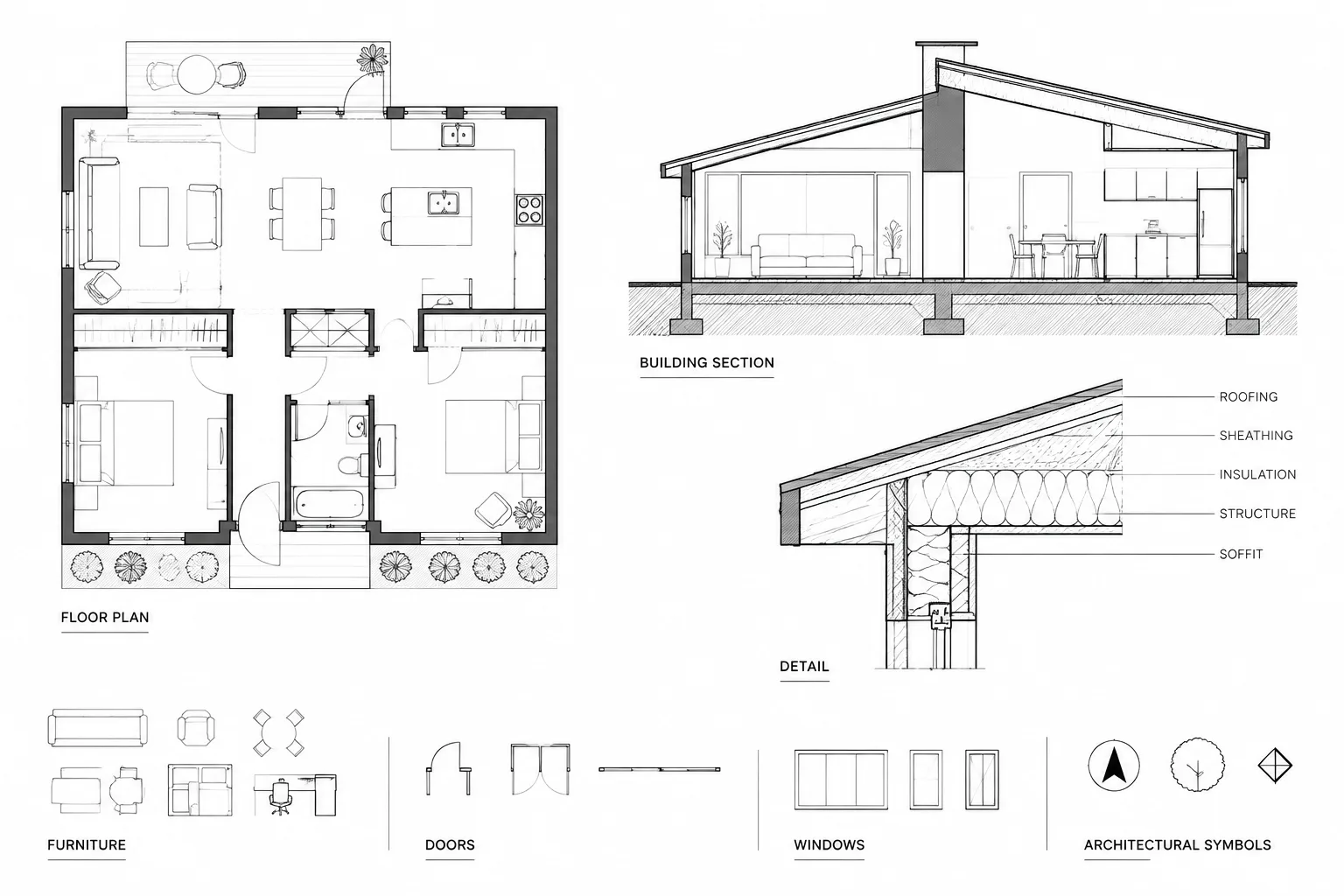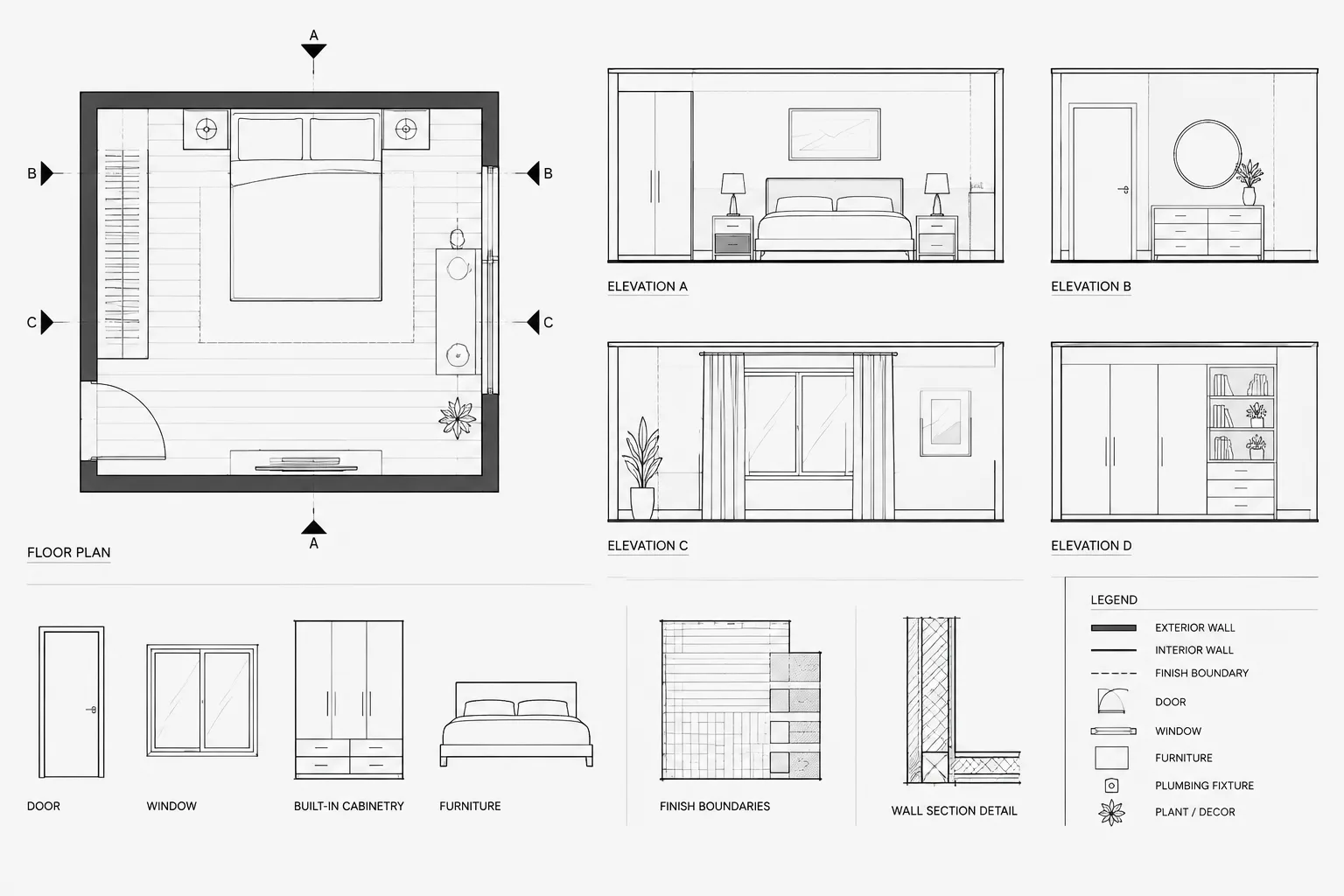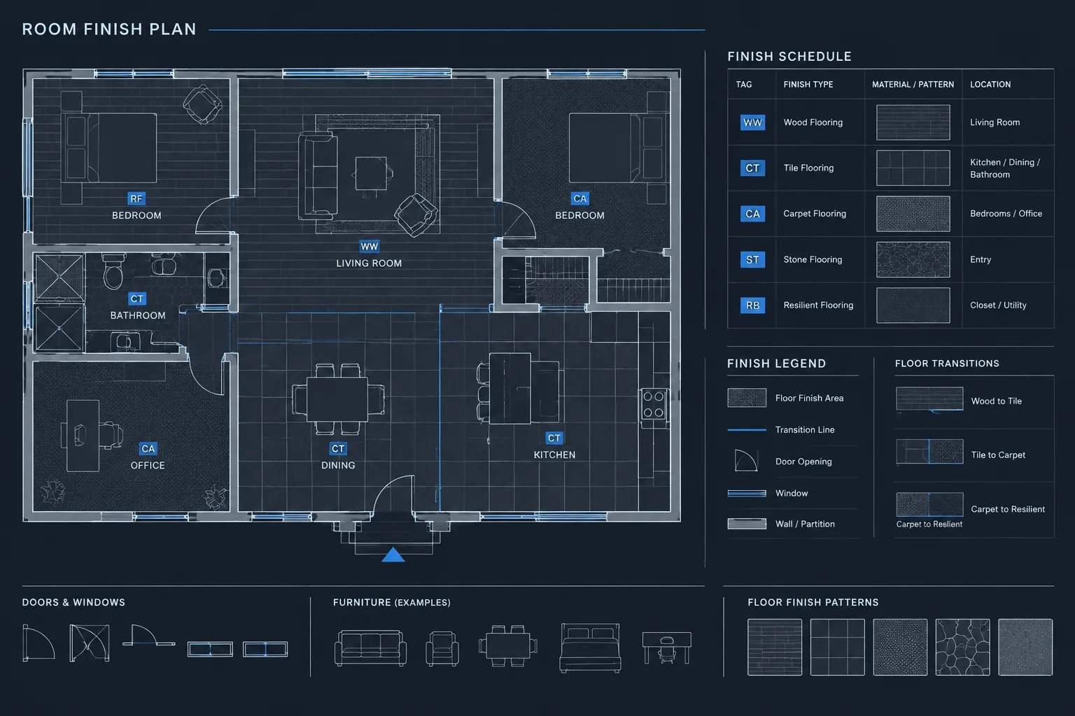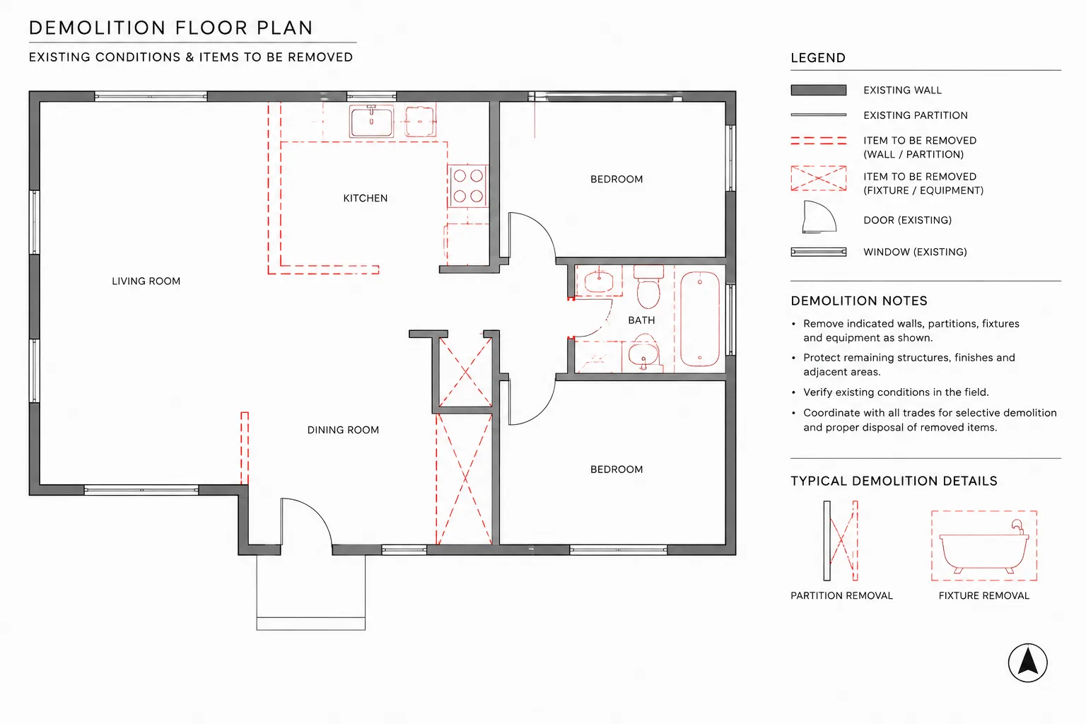
Architectural demolition plans in CAD must communicate more than what disappears from a building. They establish the relationship among existing conditions, selective removal, protected elements, relocated items, and the construction that follows.
This guide explains a practical drafting and coordination process for producing demolition drawings that remain clear as backgrounds, design decisions, and consultant information evolve. It also highlights common sources of ambiguity, including overlapping phase graphics, incomplete removal limits, unsupported assumptions, and notes that do not point to identifiable work.
Architectural demolition plans explain what must be removed, retained, relocated, or protected before new construction begins. They may resemble ordinary floor plans, but they serve a different purpose: communicating the transition between existing conditions and the proposed design.
A reliable demolition drawing is not simply a copy of the proposed plan with a few dashed walls. It should be based on verified existing information, use a consistent graphic hierarchy, and coordinate with the plans, elevations, reflected ceiling plans, and consultant drawings affected by the work. The following workflow focuses on creating architectural demolition plans in CAD that remain legible and manageable as the project changes.
Start with a Verified Existing-Conditions Base
The demolition plan should begin with the best available representation of the existing building. This may come from field measurements, a measured survey, record drawings, scanned documents, or a previously created CAD model. Each source has limitations, so avoid treating unverified information as exact.
Before drafting demolition work, review the base for:
- Overall building geometry and major wall locations
- Columns, shafts, stairs, elevators, and other fixed elements
- Door and window locations
- Changes in floor level or ceiling height
- Known structural, plumbing, mechanical, or electrical elements
- Areas that were inaccessible or could not be confirmed
Keep uncertainty visible in the project workflow. If a wall thickness, concealed condition, or overhead element is unknown, flag it for verification rather than quietly drawing an assumed condition. Notes can identify where field confirmation or exploratory work is needed, but they should not imply that hidden construction has already been established.
Separate Existing, Demolition, and New Work
One of the most important decisions is how the CAD file will distinguish the project phases. At minimum, the drawing system should be able to separate:
- Existing construction to remain
- Existing construction to be removed
- Items to be salvaged, relocated, or reinstalled
- New construction shown only when needed for coordination
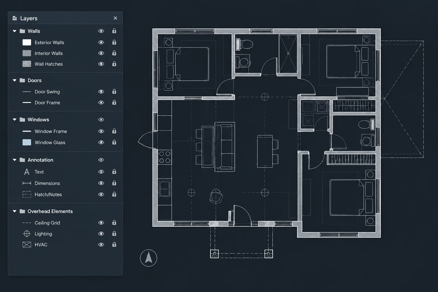
Use dedicated layers or another controlled classification method rather than relying on individual object color overrides. A layer-based approach makes it easier to change lineweights, freeze information in viewports, prepare consultant backgrounds, and check whether objects have been assigned to the correct phase.
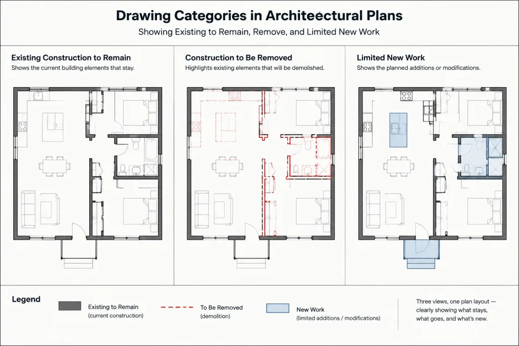
If the project uses external references, preserve a stable existing-conditions background and avoid editing it casually from the demolition sheet file. Demolition graphics can be drawn in a separate working file or controlled set of layers. The appropriate structure depends on project size, team responsibilities, and office standards, but the basic goal is the same: existing information and demolition instructions should remain distinguishable.
Establish a Clear Graphic Hierarchy
Demolition drawings are often printed in grayscale, reduced for field use, or viewed on devices with varying display quality. The plan must therefore communicate through lineweight, linetype, hatch, symbols, and notes rather than color alone.
| Information | Typical graphic objective | Coordination concern |
|---|---|---|
| Existing to remain | Visible but visually secondary | Must provide enough context to locate removal work |
| Existing to be removed | Distinct and prominent | Must not be confused with overhead or hidden elements |
| Salvaged or relocated item | Clearly tagged or noted | Destination and responsibility should be identified elsewhere when applicable |
| New construction | Limited contextual display | Should not obscure the actual demolition scope |
| Unknown or concealed condition | Qualified by an appropriate note | Requires verification before relying on it |
A dashed linetype is commonly used for removal work, but dashed lines can also represent overhead, hidden, or below-grade elements. Do not assume the linetype is self-explanatory. Include a legend or general note that defines the project convention, and use tags or keynotes where the plan could still be misread.
Draft Removal Limits Precisely
Demolition graphics should describe the actual limit of work rather than broadly marking an entire room when only part of it is affected. Precise limits help distinguish full removal from selective work.
Walls and partitions
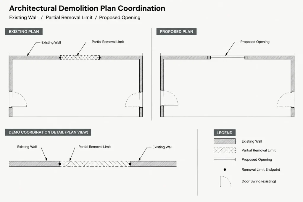
When removing a wall, indicate the complete affected segment and coordinate both ends with the proposed plan. A demolition limit that stops at an arbitrary point may leave an unclear remnant. Where a new opening is cut into an existing wall, differentiate that condition from complete wall removal. The plan may need supporting elevation, section, or detail information to explain the extent.
Doors and windows
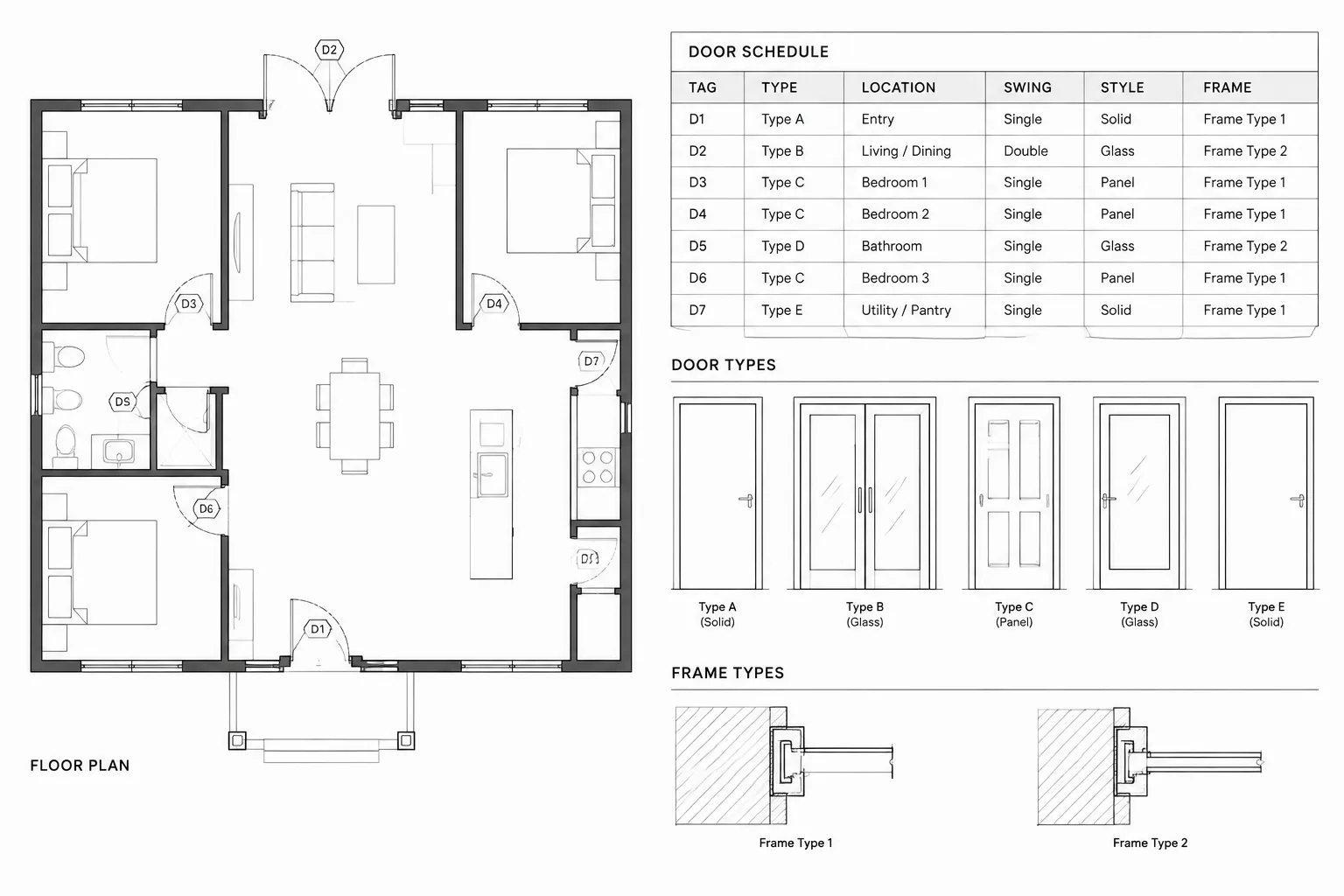
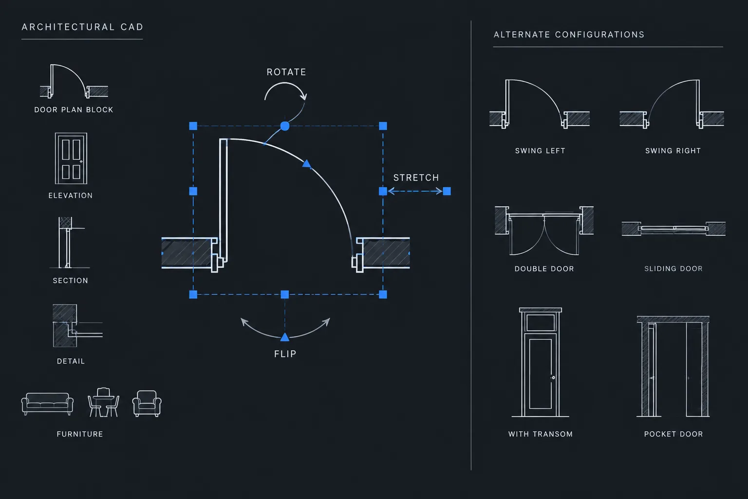
Determine whether the opening, frame, leaf, glazing, trim, or surrounding wall is being removed. A simple demolition symbol over a door may not communicate whether the opening will be infilled, enlarged, reused, or retained without its door. Coordinate these conditions with the proposed plan and door or window information.
Fixtures, casework, and equipment
Show enough existing geometry to identify the item being removed. Use tags when similar adjacent fixtures have different outcomes. Items intended for relocation should not be described only as demolished; the drawings should distinguish disposal from salvage or reuse.
Floors and ceilings
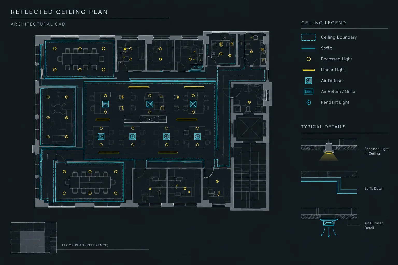
Plan graphics may need to show removal boundaries for flooring, ceilings, soffits, and overhead components. Avoid forcing every type of demolition information onto one crowded plan. A separate finish demolition plan or reflected ceiling demolition plan may be clearer when the scope is extensive.
Use Notes to Explain Actions, Not Replace Geometry
Notes are essential, but they should clarify a visible condition rather than compensate for incomplete drafting. A note such as “remove existing construction as required” can leave the contractor without a clear limit or object to price. Wherever practical, pair the instruction with a boundary, symbol, tag, or identifiable plan element.
Organize demolition notes so they can be maintained efficiently. Repeated instructions may be handled with keynotes, while unusual conditions can use local notes. Review every note for three questions:
- What specific object or area does the note address?
- What action is required: remove, retain, protect, salvage, relocate, patch, or verify?
- Does another drawing show the resulting condition?
Avoid adding broad statements about hazardous materials, structural stability, utility disconnection, or regulated work unless they have been reviewed by the appropriate project professionals. Architectural drawings should not imply conclusions that require testing, engineering, specialist investigation, or jurisdiction-specific direction.
Coordinate Demolition with the Proposed Design
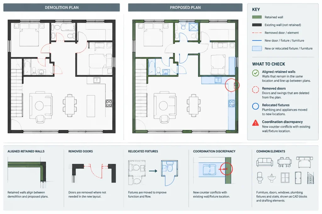
The proposed plan is one of the best tools for checking a demolition plan. Compare the two systematically rather than relying on visual memory.
- Confirm that removed walls correspond to new openings, room changes, or replacement construction.
- Check that retained walls align with the proposed layout.
- Verify that door and window changes appear consistently in both phases.
- Review floor, ceiling, and finish removal limits against the new finish design.
- Confirm that shafts, columns, stairs, and major service zones are not unintentionally marked for removal.
- Check whether removed fixtures or equipment affect plumbing, electrical, or mechanical coordination.
Overlaying or comparing controlled CAD backgrounds can reveal discrepancies, but automated comparison should not replace design review. Small geometric changes may be drafting cleanup, while a short removed wall segment could represent a significant scope item. The reviewer must interpret the difference in context.
Coordinate Other Drawing Types
Demolition scope often extends beyond the floor plan. Review related drawings for affected elements:
- Reflected ceiling plans: ceilings, light fixtures, diffusers, soffits, access panels, and ceiling-mounted equipment
- Interior elevations: casework, wall finishes, mirrors, accessories, trim, and mounted items
- Exterior elevations: windows, doors, cladding, canopies, louvers, and exterior equipment
- Sections and details: floor assemblies, roof components, vertical openings, and partial-height removals
- Consultant drawings: systems serving architectural items scheduled for removal or relocation
The architectural plan should provide a coordinated scope without attempting to redraw every consultant system. Establish where information is shown and avoid contradictory instructions across disciplines.
Keep New Work from Overloading the Plan
Limited new-work geometry can help explain demolition limits, but too much proposed construction may make the sheet difficult to read. If new walls, doors, fixtures, dimensions, and notes are all shown at full strength, the demolition instructions can disappear into the background.
Use new construction only when it adds necessary context. A lightly displayed reference may clarify why an opening is enlarged or where a partition must terminate. Detailed new-work dimensions and annotations generally belong on the proposed plan unless they are required to define a demolition limit.
Run a Focused Quality-Control Review
Before issuing the drawing, review both the CAD file and the plotted output. A useful demolition-plan checklist includes:
- Existing, removed, relocated, and new elements are graphically distinguishable.
- Linetypes remain legible at the intended sheet scale.
- Removal limits have clear endpoints and boundaries.
- Every demolition note points to an identifiable object or area.
- Door, window, fixture, and equipment changes agree with the proposed plans.
- Ceiling and finish demolition appears on the appropriate drawing.
- Demolition layers do not contain accidental proposed-work objects.
- Legends match the graphics actually used in the plan.
- Xrefs are loaded, correctly positioned, and displaying the intended layers.
- No revision cloud, markup, or temporary construction geometry remains unintentionally visible.
Plot the sheet using the same plot configuration intended for issue. Screen appearance alone will not reveal weak lineweight contrast, overly dense hatch, missing linetypes, or notes that become unreadable at print scale.
Treat the Demolition Plan as a Transition Document
A successful demolition plan connects verified existing conditions to the proposed design. Its value comes from showing exactly where that transition occurs and identifying conditions that still require confirmation.
Build the plan from a controlled existing base, classify objects by phase, use a graphic hierarchy that survives plotting, and compare every removal instruction with the resulting construction. This approach produces architectural demolition plans in CAD that are easier to review, coordinate, revise, and use alongside the rest of the drawing set.
Manage Demolition Information Through Revisions
Demolition scope can change when field conditions are confirmed or the proposed design is revised. Treating the demolition plan as a separate, coordinated deliverable helps prevent changes from being made only on the new-work plan.
When a design revision affects an existing element, review the change in both directions. First, determine whether additional material must be removed, protected, salvaged, or retained. Then confirm that the resulting condition shown on the proposed drawings is compatible with the revised demolition limit.
Control the base drawing
Identify which CAD file is the maintained source for existing conditions and who is responsible for updating it. Avoid creating unrelated copies that gradually develop different wall locations, openings, or fixed elements. If verified field information changes the base, review every demolition view that references the affected area.
Track unresolved conditions
Unknown construction should remain visible as a coordination issue until it is confirmed. Keep verification notes specific to the affected location and avoid converting assumptions into ordinary linework without review. Once information is established, update the geometry, notes, and related views together.
Review the issued sheet, not only the model space
Viewport settings, layer states, reference files, annotation visibility, and plotting conventions can alter what appears on the final sheet. A complete review should therefore include the issued sheet view and its plotted appearance, not just the working CAD geometry.
A Practical Coordination Sequence
- Compare the existing base with available field information: identify discrepancies and areas that remain unverified.
- Classify each affected element: determine whether it remains, is removed, is protected, or follows a salvage or relocation instruction.
- Draw exact limits: connect notes and symbols to recognizable objects, boundaries, and endpoints.
- Compare against proposed work: check openings, retained construction, replacement elements, finishes, and mounted items.
- Review related views: confirm that plans, reflected ceiling plans, elevations, sections, details, and consultant information do not conflict.
- Inspect the output: verify that phase distinctions, linetypes, annotations, and references remain readable in the intended sheet presentation.
This sequence is most effective when repeated after meaningful design or field-information changes. The objective is not merely to keep the CAD file tidy, but to preserve a consistent description of the transition from existing conditions to completed work.
Frequently Asked Questions
Is a demolition plan the same as an existing-conditions plan?
No. An existing-conditions plan records the building as understood before the work begins. A demolition plan uses that information as a base and adds instructions showing what is removed, retained, protected, salvaged, relocated, or otherwise affected.
Should proposed construction appear on a demolition plan?
Only when it helps define or clarify the demolition scope. Proposed geometry should remain visually secondary and should not compete with removal instructions. Detailed new-work information generally belongs on the proposed drawings.
Why should demolition objects use controlled CAD layers?
Controlled layers make it easier to manage plotting, viewport visibility, reference-file backgrounds, consultant exports, and phase checks. They also reduce dependence on individual color or property overrides that can be difficult to audit.
How should unknown concealed conditions be shown?
Show the known surrounding geometry and add a qualified note identifying the need for verification. Do not draw concealed construction as confirmed merely to complete the plan graphic.
When is a separate ceiling or finish demolition plan useful?
A separate view may be appropriate when ceiling, soffit, flooring, finish, or overhead removal becomes too dense to communicate clearly on the primary demolition floor plan. The drawing set should make the location of that information easy to understand.
What is a common demolition-plan coordination error?
A frequent error is revising the proposed plan without updating the related demolition scope. Every change affecting an existing wall, opening, fixture, finish, ceiling component, or mounted item should trigger a review of both phases.