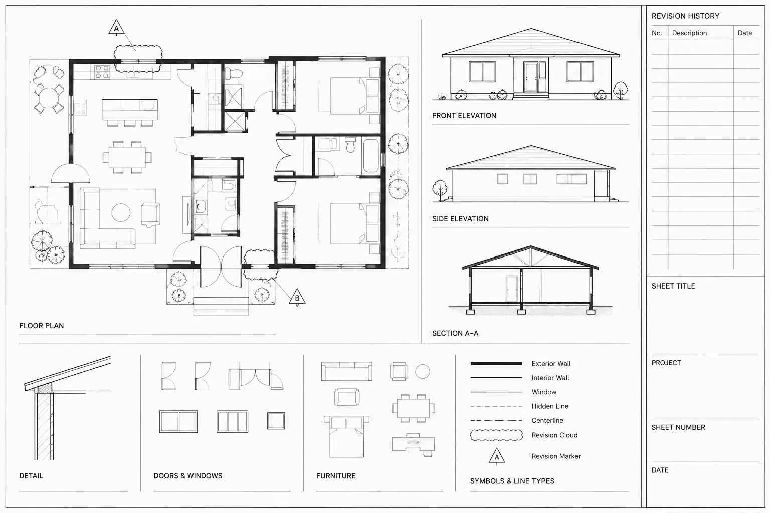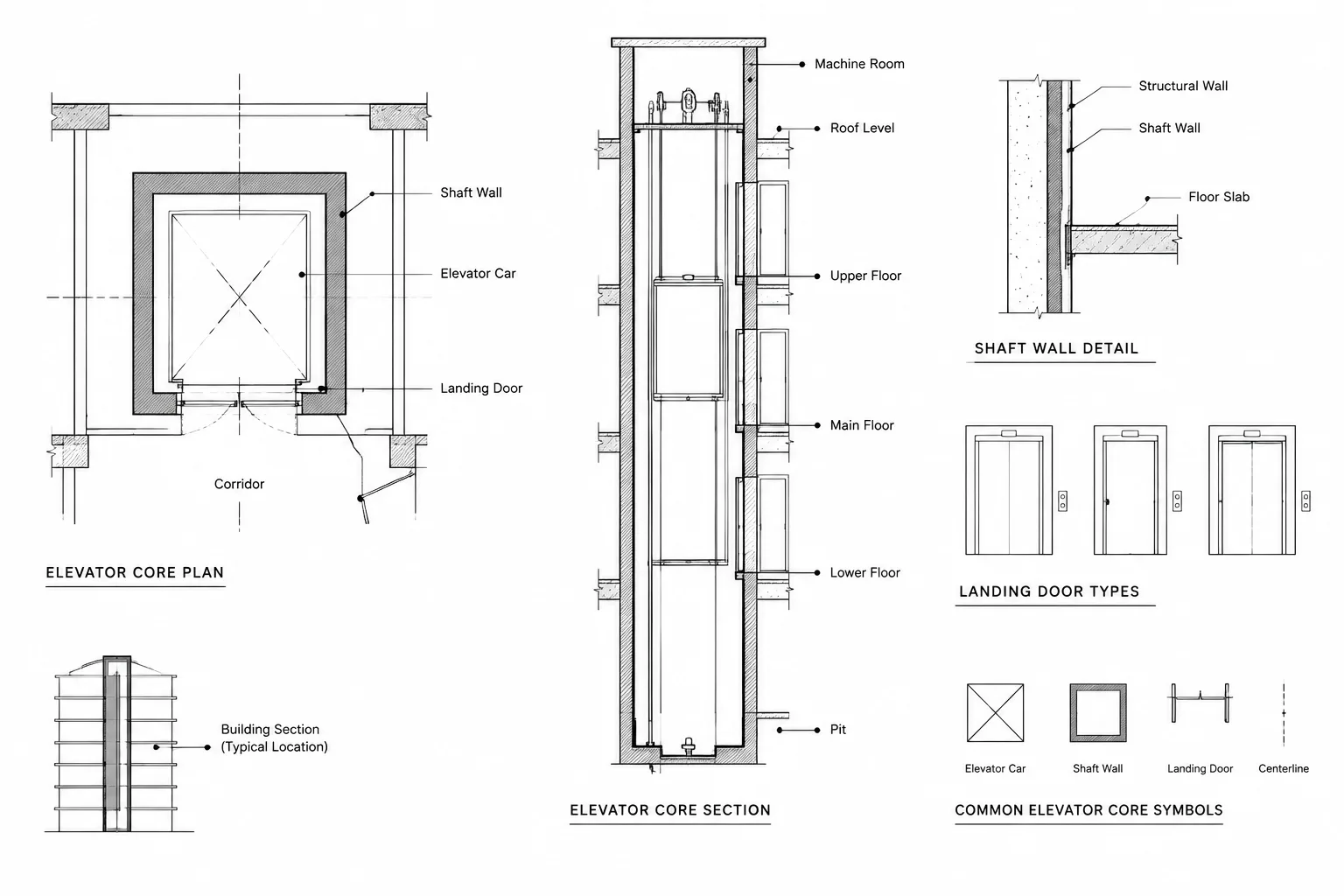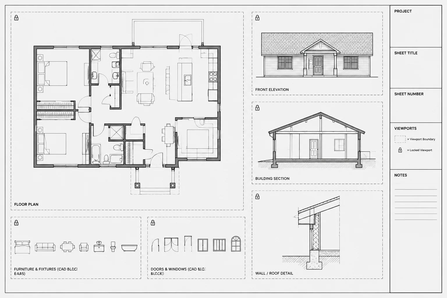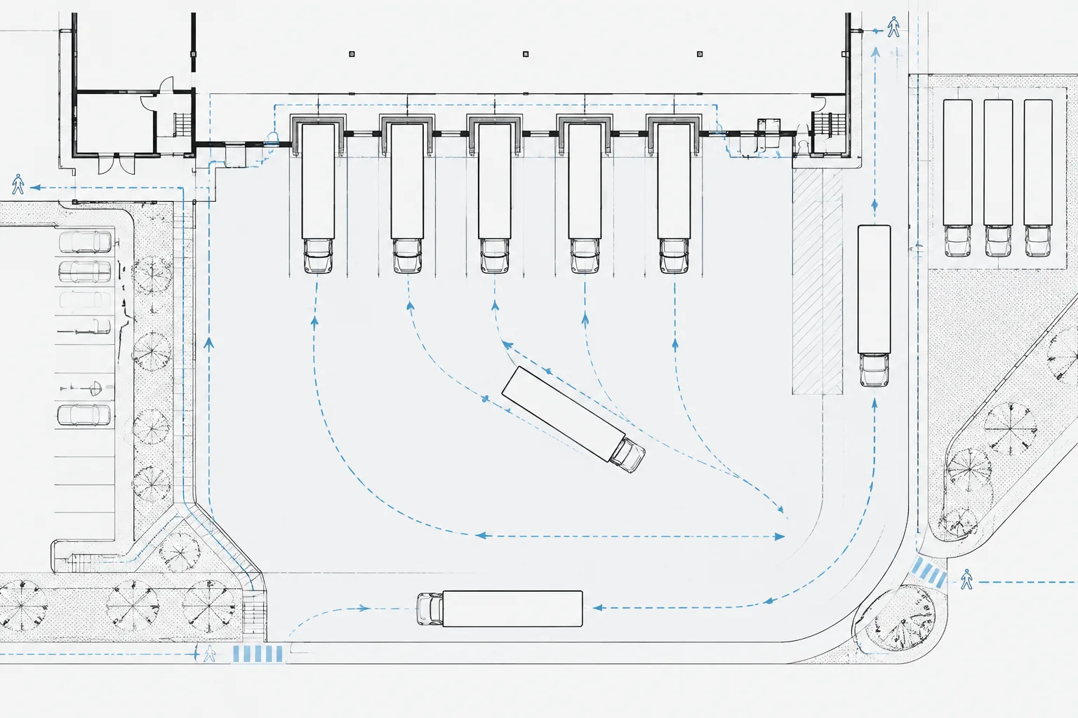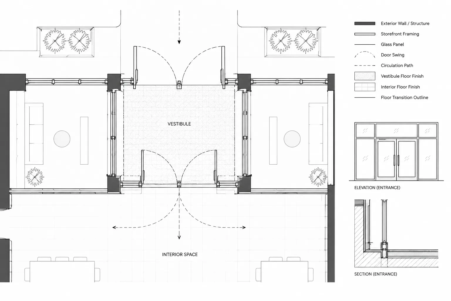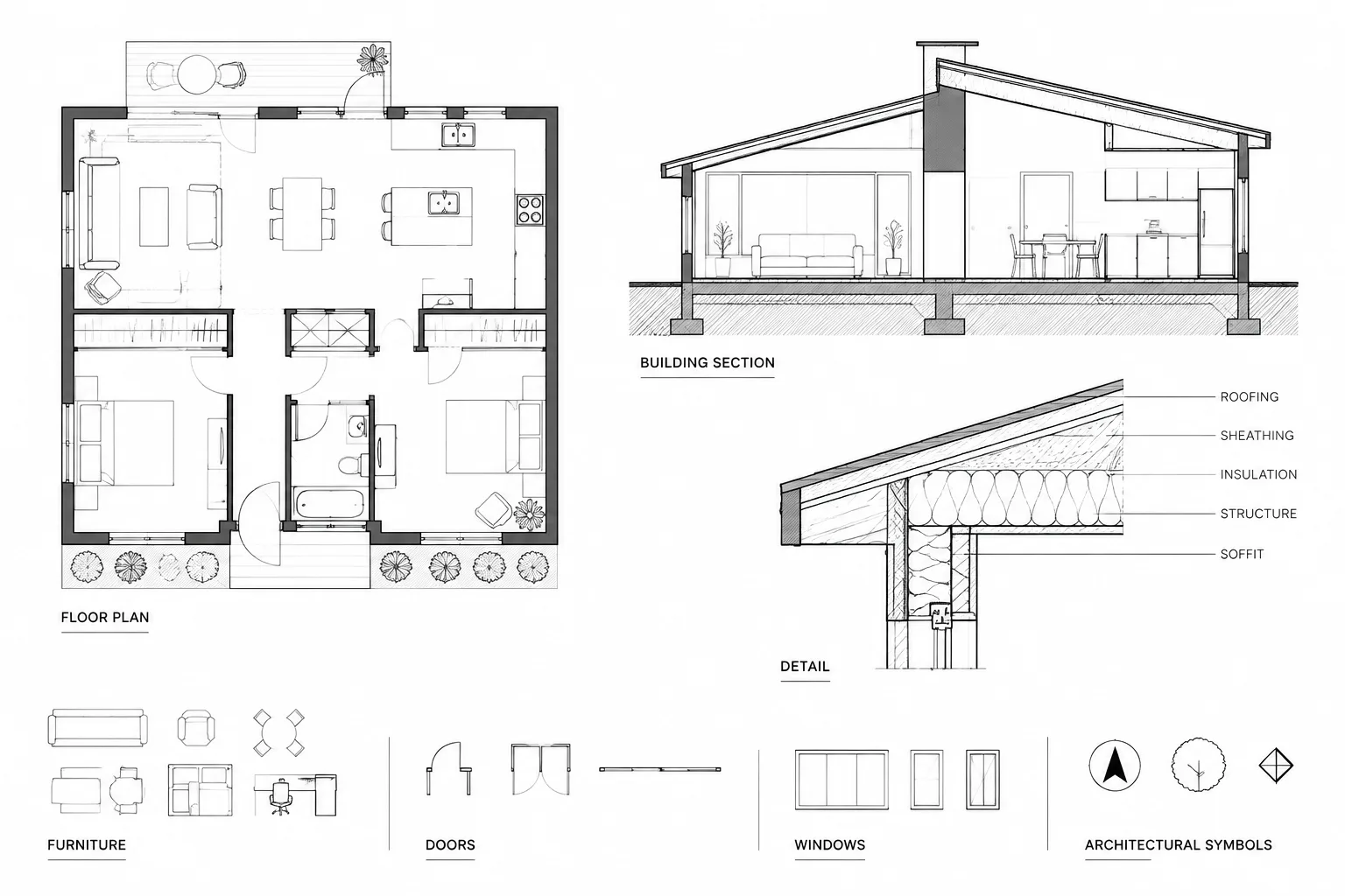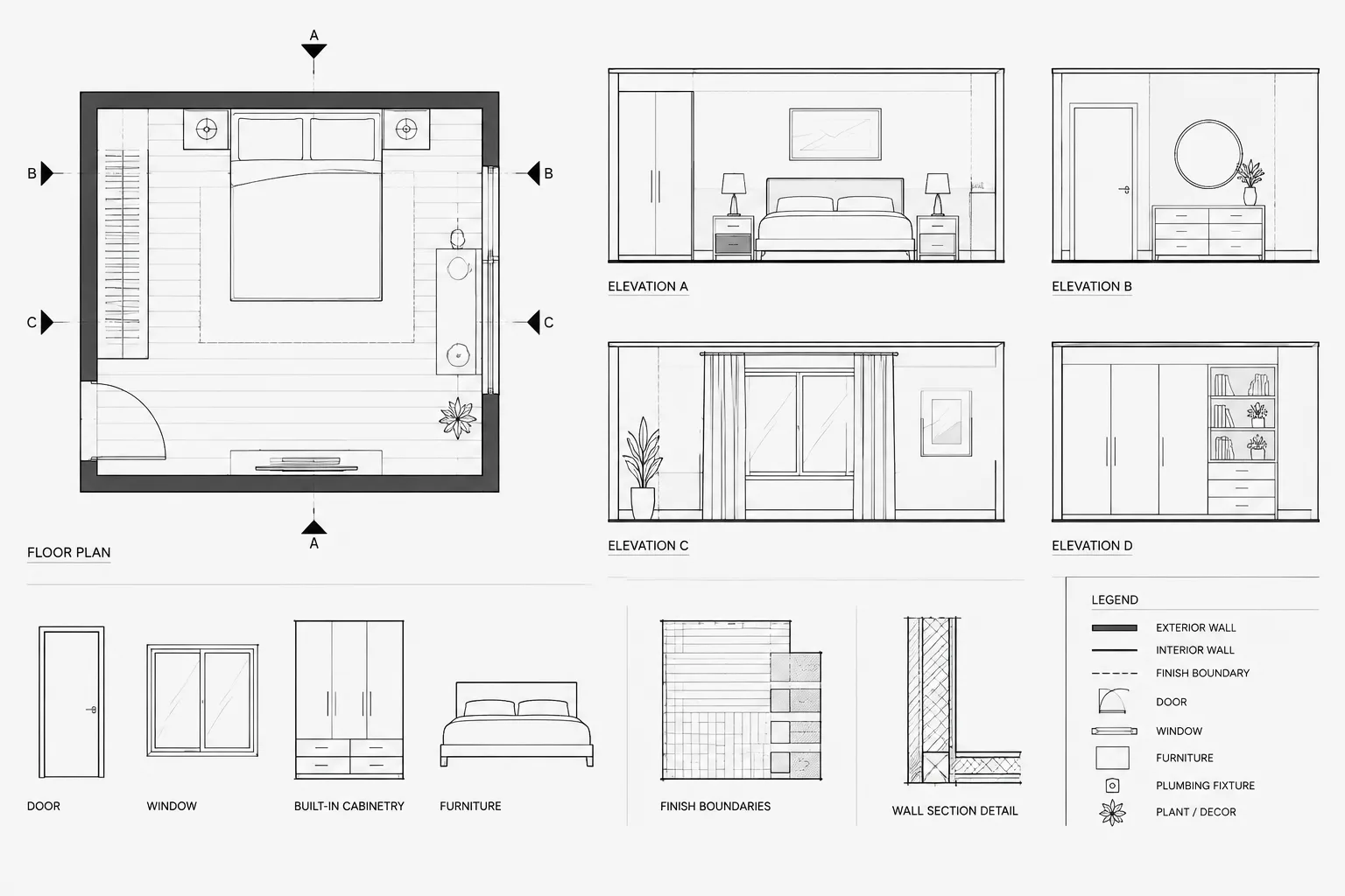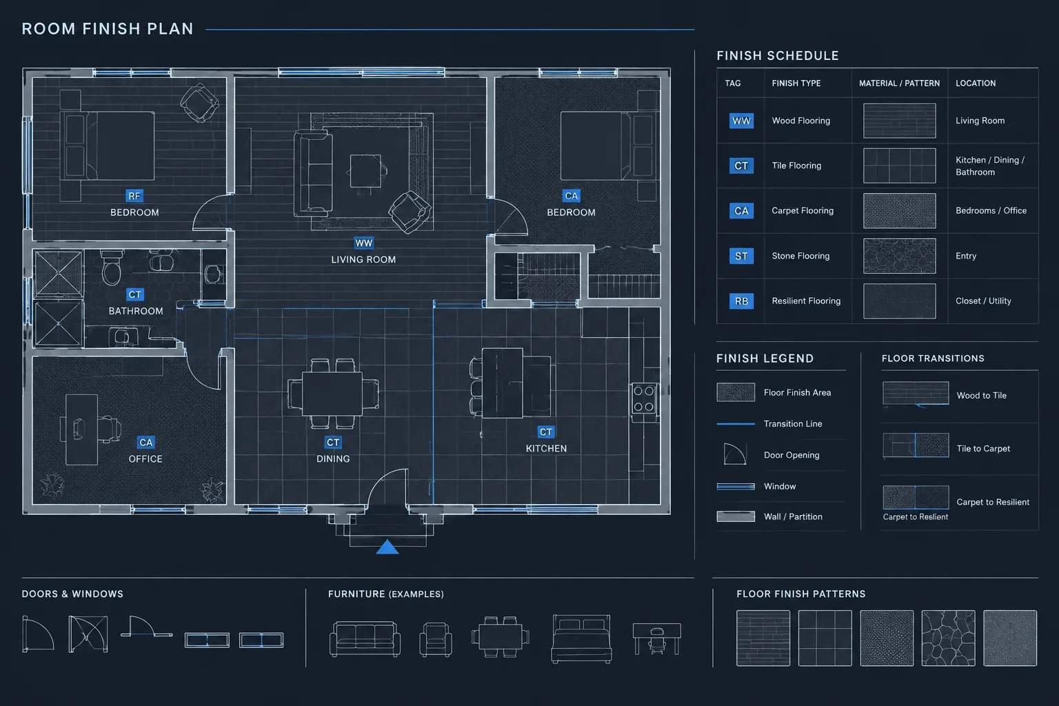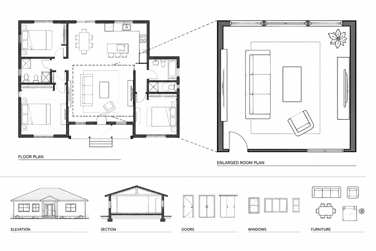
Enlarged floor plans make complex spaces easier to document, but enlargement also increases the visibility of coordination errors. Walls, openings, fixtures, equipment, dimensions, and references must remain consistent with the overall plan and every connected drawing.
This guide explains a practical CAD workflow for defining the enlarged area, managing shared geometry, separating view-specific annotation, coordinating related views, and reviewing the final sheet. Use it as a drafting framework rather than a substitute for project requirements, office standards, or professional review.
Enlarged floor plans provide more drawing space for areas that cannot be documented clearly at the scale of the overall building plan. Restrooms, kitchens, stairs, lobbies, equipment rooms, and other coordination-heavy spaces often need enlarged views for dimensions, fixture locations, wall types, clearances, and detail references.
The main challenge is not creating a larger-looking view. It is keeping that view connected to the same architectural geometry and project information shown elsewhere. An enlarged plan that drifts away from the overall floor plan can create contradictory dimensions, misplaced openings, or obsolete construction information. A reliable workflow therefore treats the enlarged plan as a coordinated view of the project rather than an independent sketch.
Decide What the Enlarged Plan Must Communicate
Before setting up the drawing, identify why the area needs enlargement. More scale is useful only when it supports additional information or improves legibility.
An enlarged plan may be needed to show:
- Closely spaced dimensions and locating information
- Plumbing fixtures, appliances, casework, or built-in equipment
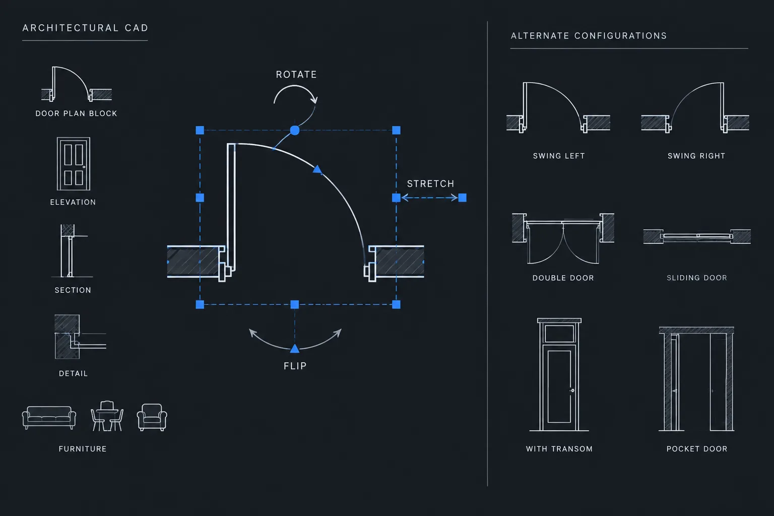
- Door swings, frames, hardware-related coordination, and adjacent clearances
- Floor openings, recesses, curbs, depressions, or level changes
- Wall types, finish transitions, and material boundaries
- Accessibility-related layouts that require project-specific verification
- Interior elevation, section, and detail callouts
- Specialty items supplied by consultants, vendors, or fabricators
Define the enlarged plan’s purpose before adding notes. A restroom plan focused on partitions and accessories has different coordination needs from an enlarged stair plan or commercial kitchen layout. This scope decision helps prevent the view from becoming an unreadable collection of every available layer.
Use One Authoritative Source for Building Geometry
Whenever practical, the overall plan and enlarged plan should display the same walls, columns, openings, and fixed architectural elements. The preferred method is generally to create separate views or viewports of shared model-space geometry. If the project uses external references, the enlarged plan can display the relevant portion of the same referenced floor plan.
Avoid copying a room or plan fragment to an empty area merely to make an enlarged drawing. Copied geometry creates a second version that must be updated manually. A moved door, revised wall, or changed shaft can then appear correctly in one plan but remain outdated in the duplicate.
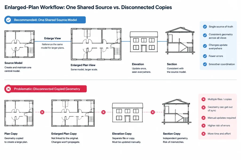
If duplication is unavoidable because of project structure or a required deliverable, make the responsibility explicit. Identify which file controls the geometry, document the update process, and compare the duplicate against its source during every significant revision.
Separate View-Specific Information
Shared geometry does not mean every annotation must appear in every view. Overall plans and enlarged plans serve different reading purposes. Keep view-specific dimensions, notes, tags, and callouts on layers or within drawing spaces that can be controlled independently.
A useful division is:
- Shared model information: walls, doors, windows, columns, fixtures, casework, shafts, and permanent equipment.
- Overall-plan annotation: major dimensions, room identification, broad circulation information, and references to enlarged areas.
- Enlarged-plan annotation: detailed dimensions, accessory tags, equipment labels, local notes, and detail references.
This arrangement reduces overlapping text and prevents detailed notes from appearing at an inappropriate scale on the general plan.
Establish a Clear Enlarged-Plan Boundary
The enlarged view should include enough surrounding context for orientation and coordination. Cropping exactly at the room finish line can conceal wall thicknesses, adjacent door swings, structural elements, or corridor conditions that affect the layout.
Choose a boundary that captures the subject area plus the neighboring construction needed to understand it. For a restroom, that may include the entrance, surrounding partitions, plumbing chase, and nearby corridor. For a kitchen, it may include adjacent doors, service access, columns, and connections to dining or storage areas.
Use a consistent boundary concept across related enlarged plans. Irregular clipping can be appropriate, but it should not make the reader struggle to determine where the view sits within the building.
Reference the Enlarged Area from the Overall Plan
The overall floor plan should direct the reader to the enlarged view. This is commonly done with a boundary or callout that identifies the enlarged area and provides the corresponding drawing reference.
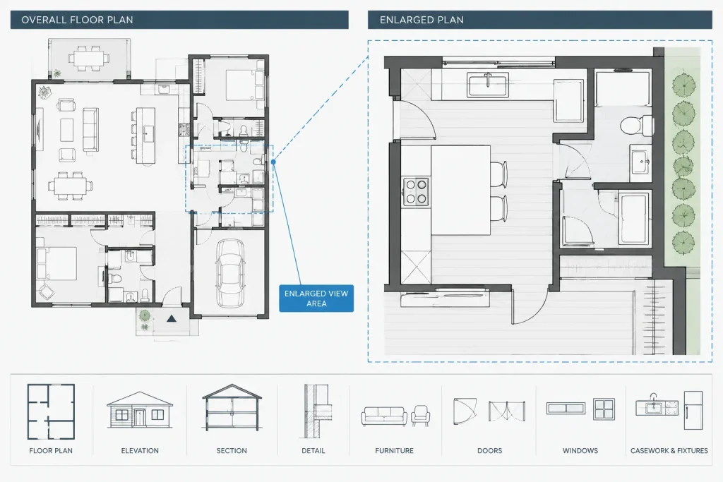
The reference should be placed where it is visible without obscuring critical plan information. Its extents should agree with the actual enlarged view closely enough that readers understand what is included. If the enlarged plan boundary changes, update both the view and its source callout.
For projects with many repeated or similar spaces, include room names, room identifiers, grid references, or nearby orientation cues. A detail number alone may not be enough to distinguish one enlarged area from another.
Control Graphic Hierarchy at the Enlarged Scale
An enlarged viewport does not automatically produce a well-composed drawing. Layer visibility, lineweight, hatch density, symbols, and annotation must be reviewed at the plotted scale.
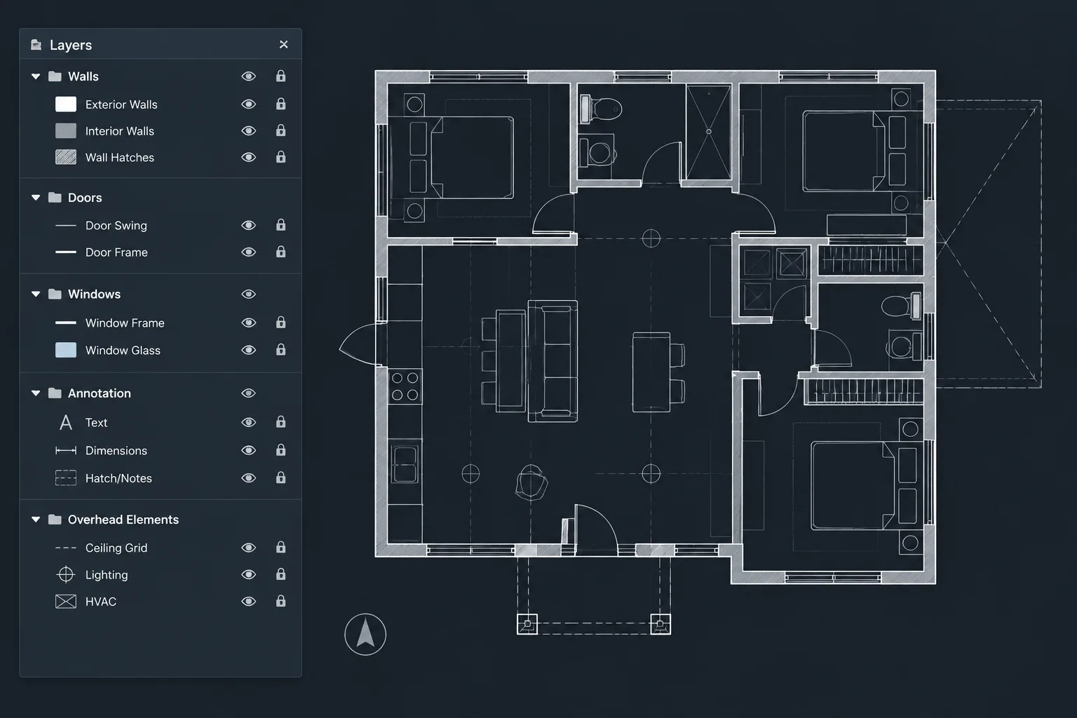
Primary cut elements should remain visually dominant. Elements beyond or overhead should be lighter or differentiated according to the project’s drafting conventions. Fixtures and equipment need enough definition for coordination without overpowering walls and openings.
Watch for hatch patterns and complex blocks that become too dense when viewed more closely. A block created for a small overall plan may contain unnecessary detail at an enlarged scale, while a highly detailed manufacturer’s drawing may introduce clutter. Simplify representations according to the purpose of the construction document, but retain geometry needed for layout and coordination.
Build Dimensions Around Installation Logic
Detailed plans often fail when dimensions are added wherever empty space happens to be available. Instead, organize dimensions according to how the area is located and constructed.
Typical dimension priorities include:
- Primary wall and opening locations
- Centerlines or faces used to locate fixtures and equipment
- Clear spaces that require design verification
- Casework extents and relationships to adjacent construction
- Floor openings, recesses, and changes in level
- Critical relationships between architectural and consultant items
Avoid dimensioning the same relationship differently on the overall plan and enlarged plan. If both views need the information, confirm that they use the same reference points and values. Also avoid relying on scaled measurements from the plotted sheet when an explicit dimension or note is necessary.
Coordinate Related Drawings
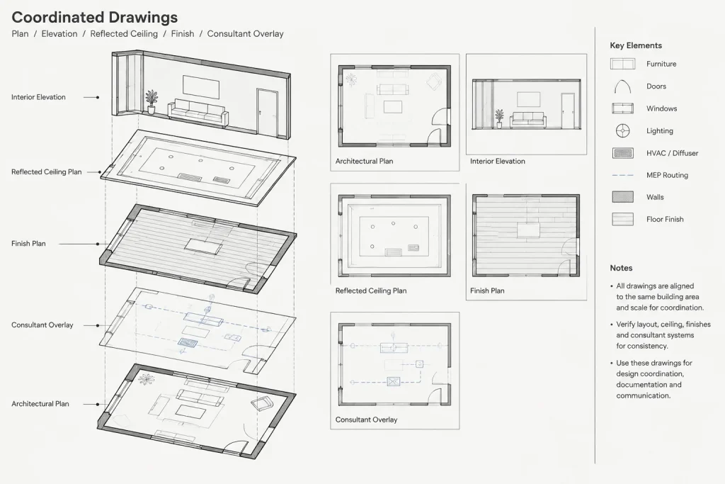
An enlarged plan often acts as a hub connecting several drawing types. Its callouts and tags should agree with elevations, sections, schedules, ceiling plans, finish drawings, and consultant backgrounds.
| Related drawing | Items to compare |
|---|---|
| Overall floor plan | Walls, openings, room identifiers, grids, and enlarged-area reference |
| Interior elevations | Casework, fixtures, accessories, openings, finishes, and elevation markers |
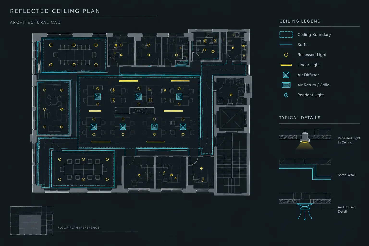
| Reflected ceiling plan | Soffits, ceiling changes, lighting relationships, diffusers, and access requirements |
| Finish plan or schedule | Material boundaries, room names, base conditions, and transitions |
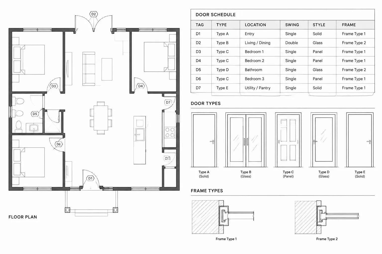
| Door and window information | Tags, types, handing, frame relationships, and opening locations |
| Consultant drawings | Structural elements, plumbing connections, equipment, devices, and penetrations |
Do not assume that matching references guarantee matching geometry. Open the related views and compare the actual locations. A callout may point to the correct detail while the detail itself still shows an earlier design.
Handle Repeated Rooms Carefully
Repeated rooms can sometimes share an enlarged plan, but only when their geometry, orientation, equipment, and construction conditions are genuinely equivalent. Mirrored or slightly modified rooms may require separate views or clearly documented variations.
When one enlarged plan applies to multiple locations, identify exactly which rooms it covers. Note exceptions in a controlled way rather than adding scattered qualifications that are easy to miss. Recheck shared plans whenever one instance changes; a local revision may invalidate the assumption that all instances remain typical.
Recommended CAD Workflow
- Confirm the source geometry. Identify the model or external reference that controls walls, openings, fixtures, and other permanent elements.
- Define the view boundary. Include the subject area and enough adjacent context to support coordination.
- Create the sheet view. Set up a viewport or equivalent view method at an appropriate project-selected scale.
- Control visible layers. Hide unrelated information while retaining elements needed for construction and coordination.
- Add view-specific annotation. Place dimensions, tags, notes, and callouts where they remain legible and logically grouped.
- Add the source reference. Mark the enlarged area on the overall plan and verify the drawing reference.
- Coordinate connected views. Compare elevations, sections, schedules, ceilings, finishes, and consultant information.
- Review the plotted result. Check lineweights, text size, clipping, hatch density, and reference readability in the final output format.
Quality-Control Checklist
- The enlarged plan uses the current authoritative building geometry.
- The boundary includes sufficient adjacent context.
- The overall plan contains a readable reference to the enlarged view.
- View titles, room identifiers, and drawing references agree.
- Dimensions use consistent and intentional reference points.
- Door swings, fixtures, casework, and equipment match related drawings.
- Interior elevation and section markers point to the correct views.
- No outdated copied geometry is hidden outside the visible crop.
- Layer overrides do not conceal required project information.
- Annotations do not overlap geometry or depend on screen color for meaning.
- The plotted sheet has been reviewed, not just the model-space display.
Keep the Enlarged Plan Connected to the Project
A successful enlarged plan is not an isolated drawing with extra detail. It is a controlled view that clarifies a complex part of the building while remaining consistent with the overall plan and related documents. Shared geometry, deliberate annotation, clear references, and repeated cross-checks are more important than simply increasing the drawing scale.
When the workflow is organized around one authoritative source and clearly separated view-specific information, enlarged floor plans become easier to revise, review, and issue. They also give contractors and consultants a more reliable place to understand the relationships that are difficult to communicate on a general floor plan.
Manage Revisions Without Breaking Coordination
Revision control should follow the same information hierarchy used to create the enlarged plan. Update the authoritative geometry first, regenerate or refresh dependent views, and then review view-specific annotation. Moving dimensions or notes before the underlying plan is current can conceal conflicts rather than resolve them.
When a room changes, trace the effect beyond its visible boundary. A shifted partition may affect an adjacent room, ceiling alignment, finish transition, door information, equipment connection, or interior elevation. The enlarged plan should therefore be reviewed as part of a connected drawing set rather than as an isolated sheet detail.
Use a Focused Redline Sequence
- Geometry: Compare walls, openings, columns, shafts, fixtures, casework, and fixed equipment with the controlling plan.
- Annotation: Check dimensions, tags, notes, room identifiers, and reference markers after geometry is confirmed.
- Relationships: Review clear spaces, alignments, access zones, and interfaces between architectural and consultant elements.
- References: Confirm that plan callouts, elevations, sections, schedules, and detail markers lead to the intended information.
- Output: Inspect the plotted or published sheet for clipping, lineweight conflicts, dense hatches, and unreadable overlaps.
Troubleshoot Common Enlarged-Plan Problems
The Overall Plan and Enlarged Plan Do Not Match
Determine whether the enlarged plan contains copied geometry, an outdated external reference, or a separate file that was not updated. Establish which source controls the design before editing either view. Correcting both versions independently can preserve the underlying coordination problem.
Dimensions Appear Correct but Conflict With Other Drawings
Compare the dimension origins and endpoints, not only the displayed values. Different views may be dimensioned to different wall faces, centerlines, finishes, or equipment references. Use intentional project reference points and make the same design relationship clear wherever it appears.
The Enlarged View Is Too Crowded
Remove unrelated layers, reorganize annotation by subject, and simplify graphic representations that exceed the view’s purpose. Do not solve crowding by hiding information required to understand the construction. If several systems compete for the same space, related information may need to be communicated through coordinated elevations, sections, schedules, or other views.
The View Is Clear on Screen but Poor in Output
Review the actual issue format. Screen color, zoom level, and display settings can disguise weak lineweight hierarchy, clipped notes, dense patterns, or overlapping symbols. Output review is part of drawing coordination, not merely a presentation check.
Use the Enlarged Plan as a Coordination Index
A well-organized enlarged plan helps readers move between related project information. Its value comes from showing where elements are located and directing readers to the views or schedules that explain them further. Clear identifiers and disciplined references reduce the need to repeat the same information in several places.
Before issue, ask whether a reviewer can identify the area, understand its relationship to the building, locate critical elements, and follow every reference without guessing. If not, improve the view boundary, annotation hierarchy, or connected references before adding more detail.
Frequently Asked Questions
Should an enlarged floor plan use copied geometry?
Shared or referenced geometry is generally easier to coordinate because revisions can flow from an authoritative source. If duplication is required by the project workflow, identify the controlling file and include comparison of the duplicate in revision reviews.
What belongs on an enlarged plan instead of the overall plan?
Place information according to reading purpose. The overall plan should retain broad building organization and the reference to the enlarged area. The enlarged plan can carry local dimensions, fixture and equipment labels, accessory tags, material transitions, and closely spaced detail references.
How much surrounding context should the enlarged view show?
Show enough adjacent construction to explain access, wall thickness, openings, structural relationships, and connections to neighboring spaces. A crop that follows the room boundary too closely may hide conditions needed for coordination.
Can repeated rooms share the same enlarged plan?
They can share a view only when the applicable geometry, orientation, equipment, and construction conditions are genuinely equivalent. Identify every location covered and document exceptions clearly. Recheck the shared view whenever any instance changes.
Where should enlarged-plan dimensions be placed?
Organize them around installation and layout logic rather than available blank space. Use consistent reference points, avoid contradictory duplicate dimensions, and keep dimension strings readable without obscuring important geometry.
How should accessibility-related layouts be handled?
Show the geometry and clear spaces needed for project coordination, but verify them against the requirements adopted for the project and the applicable design criteria. Do not treat a generic CAD block or visual clearance symbol as proof of compliance.
What should be checked before issuing the sheet?
Compare the enlarged plan with the overall plan, connected elevations and sections, ceiling and finish information, schedules, and consultant backgrounds. Then review the final output for clipping, annotation conflicts, graphic hierarchy, and readable references.