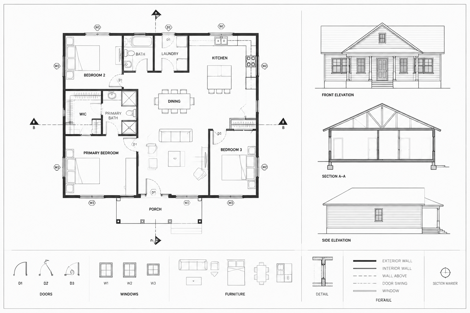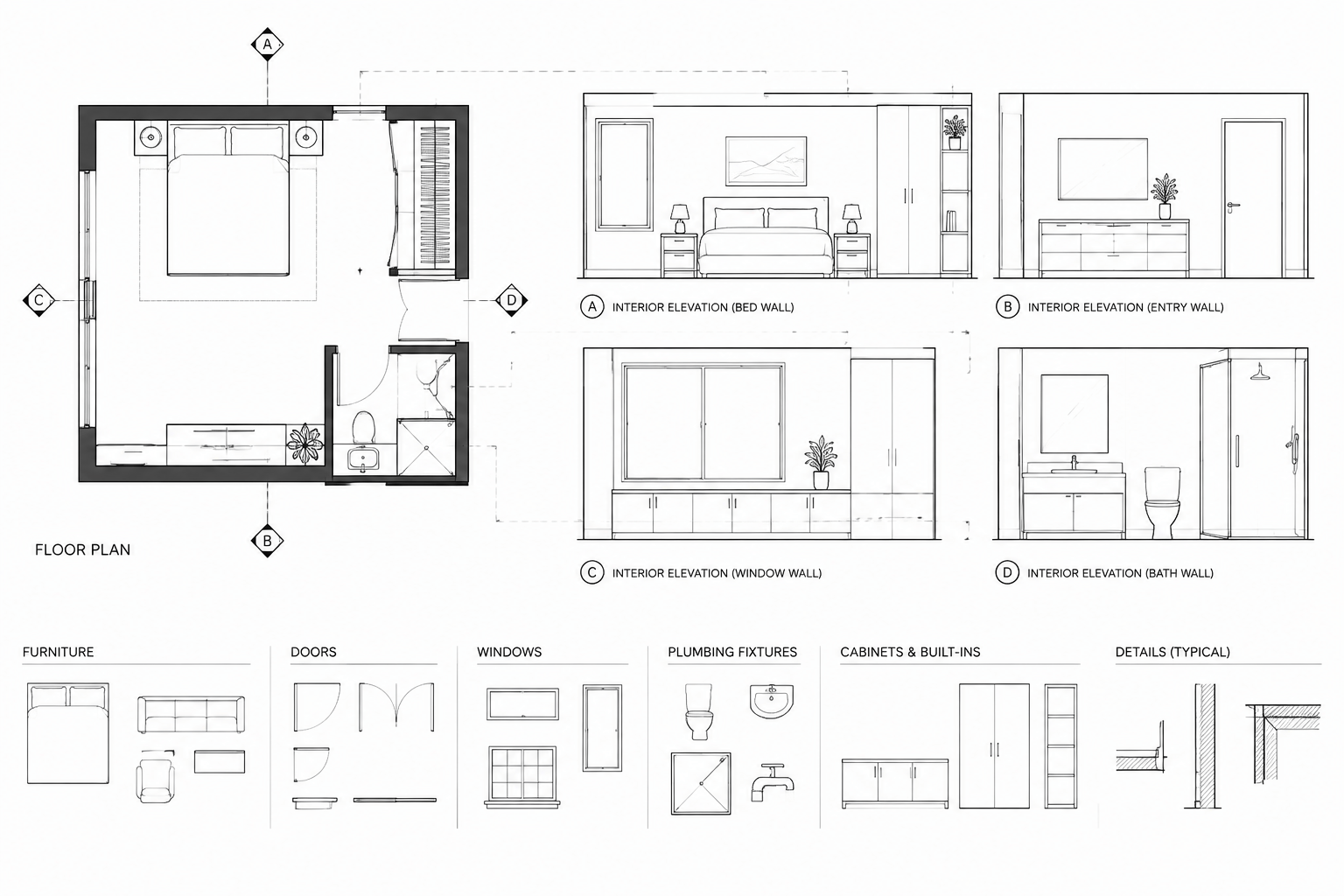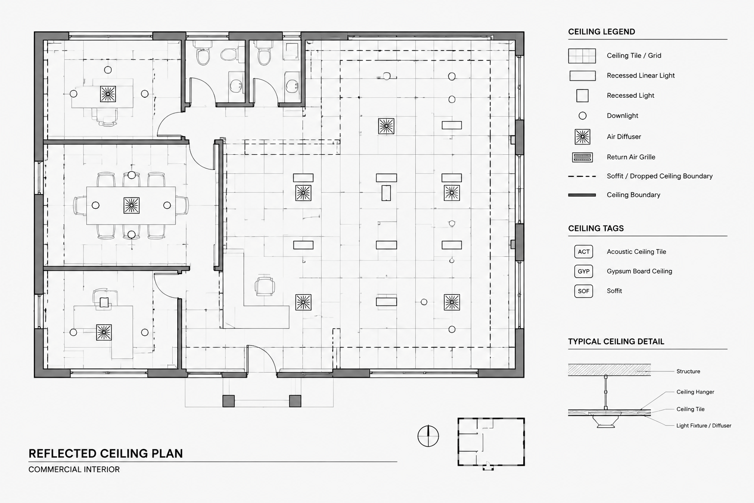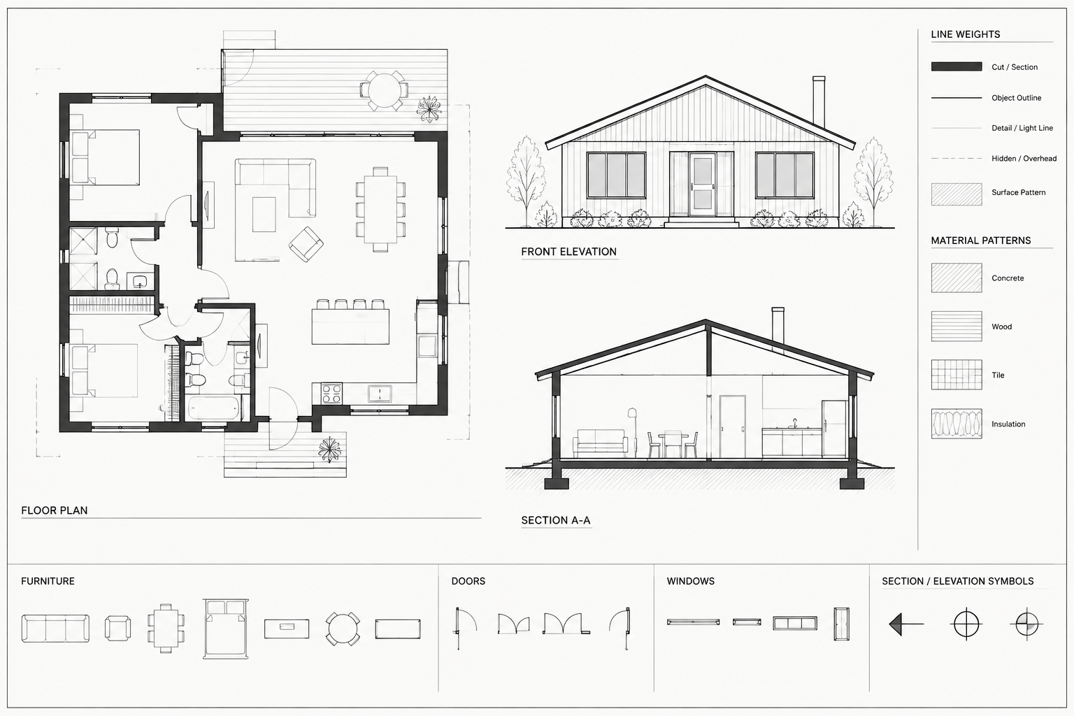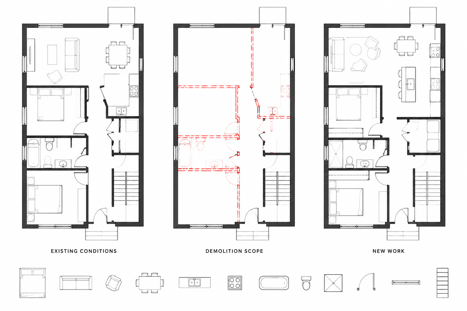
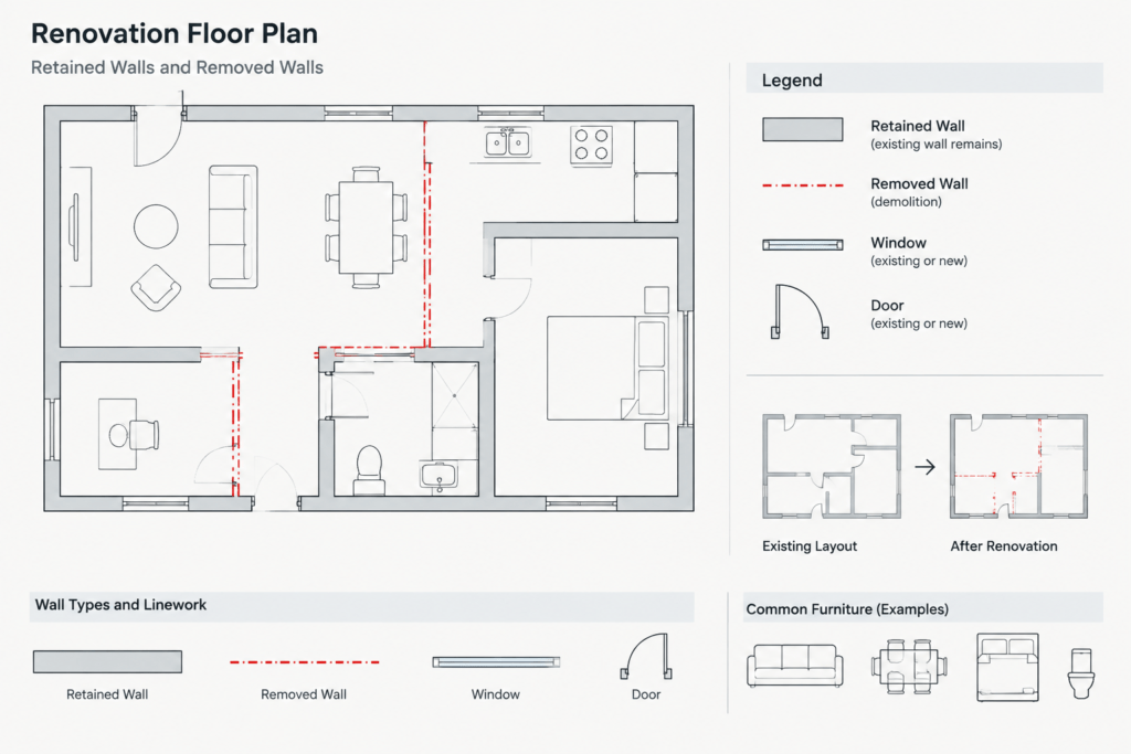
Renovation drawings must explain three different conditions: what is present now, what will be removed, and what will remain or be constructed. When these conditions are mixed into one crowded CAD plan, contractors can struggle to distinguish verified information from proposed work. A better approach is to organize existing, demolition, and new work information as coordinated views of the same project.
This workflow applies to tenant improvements, residential remodeling, interior renovations, additions, and many adaptive-reuse projects. It focuses on drawing organization rather than code interpretation. Actual demolition methods, structural modifications, hazardous-material procedures, temporary support, and required permits must be evaluated by qualified project professionals.
Understand the Purpose of Each Plan
The three plan types are related, but each answers a different question. Their content and graphic emphasis should reflect that purpose.
| Plan type | Primary question | Typical emphasis |
|---|---|---|
| Existing conditions plan | What is currently present? | Surveyed walls, openings, fixtures, levels, and relevant site observations |
| Demolition plan | What is removed, altered, relocated, or protected? | Demolition limits, retained construction, notes, and coordination references |
| New work plan | What is the completed design intent? | New construction, final room layout, doors, fixtures, dimensions, and references |
An existing conditions plan is not automatically a complete record of concealed construction. A demolition plan is not simply the proposed plan with dashed walls. A new work plan should show the intended finished arrangement without forcing the reader to reconstruct it mentally from demolition graphics.
Begin with a Reliable Existing-Conditions Base
The quality of the renovation set depends on the quality of its base information. Available record drawings can be useful, but they may not reflect later alterations or actual field conditions. Distinguish between information taken from documents, information observed in the field, and information that remains unverified.
Build the existing plan from controlled references such as field measurements, survey information, consultant backgrounds, photographs, and available record documents. Avoid filling gaps with assumptions just to make the geometry appear complete.
Record only relevant and supportable information
Depending on the project scope, the existing plan may include:
- Exterior and interior walls within or near the work area
- Doors, windows, stairs, columns, and major level changes
- Plumbing fixtures, casework, and fixed equipment affected by the work
- Visible ceiling, floor, or structural features that influence the design
- Room names or identifiers used during field documentation
- Adjacent areas needed to explain access, continuity, or protection
Do not imply that a wall is nonstructural, that a utility is inactive, or that concealed materials are known unless that conclusion has been verified through the appropriate investigation.
Separate Drawing Status from Object Type
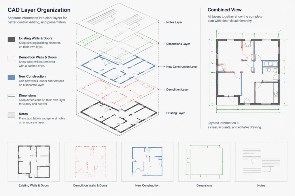
A useful CAD structure identifies both what an object represents and its project status. A wall layer alone may not be enough in a renovation drawing because existing, removed, and new walls need different display behavior.
One project might use descriptive layer groups such as existing walls, demolition walls, new walls, existing doors, demolition doors, and new doors. The exact naming convention should follow the office or project CAD standard. Consistency matters more than any particular prefix.
Status-based organization offers several benefits:
- Existing information can be screened or subdued.
- Demolition scope can receive a distinct linetype or graphic treatment.
- New work can plot with stronger emphasis.
- Plan views can be checked by isolating one status at a time.
- Objects are less likely to appear accidentally on the wrong sheet.
Keep annotation organized as well. Demolition notes, new work notes, dimensions, room labels, and callout symbols should not all be placed on one general text layer if they need to appear in different views.
Create the Demolition Plan from the Existing Plan
The demolition plan should begin as a coordinated version of the verified existing base. Classify each relevant object according to what happens to it: remain, remove, relocate, modify, or protect. Not every office uses all of these categories, but the drawing should communicate the distinctions needed for the project.
Show retained construction as context
Existing construction that remains helps locate demolition work. It should usually be visible but graphically secondary. If retained walls are too bold, the demolition scope disappears. If they are too faint, the contractor loses the context needed to locate the work.
Make removal limits unambiguous
Demolition graphics should indicate the full extent of removal rather than only the most obvious object. For example, removing a door may also affect its frame, hardware, adjacent finish, or opening preparation. The drawings and specifications should coordinate who is responsible for each associated item.
Use notes where linework cannot explain the scope. Helpful notes describe an action and identify the object, such as removing an existing fixture or protecting an adjacent finish. Avoid vague labels such as “demo as required” unless another drawing or specification clearly defines the requirement.
Do not use demolition plans to design temporary conditions
A demolition plan documents scope, but it does not automatically resolve sequencing, temporary shoring, weather protection, utility shutdowns, or occupant separation. Include project-specific information when it has been developed and coordinated. Otherwise, do not suggest that a simple dashed outline addresses these responsibilities.
Develop the New Work Plan as the Finished Condition
The new work plan should present the completed architectural layout clearly. Copying the demolition plan and drawing new walls over it often leaves removed objects, demolition notes, and obsolete symbols in the file. Instead, create a controlled view in which demolition information is hidden and retained existing construction forms the base for the proposed design.
Show new walls, openings, doors, fixtures, casework, and other permanent work according to the project scope. Existing elements that remain can be shown with reduced emphasis where needed for orientation. Elements removed during demolition generally should not remain visible unless a special reference graphic is necessary.
Dimension the intended result
New work dimensions should locate the proposed construction and explain the final design intent. Avoid relying on demolition dimensions to establish new walls. A removed partition may not provide a dependable construction reference after demolition has started.
Select dimension origins that are expected to remain available, such as verified structural grids, retained wall faces, established control lines, or other coordinated reference points. Dimensioning methods should match the project documentation standard and the way the work will be laid out in the field.
Coordinate Objects That Change Status
Some items do not fit neatly into “remove” or “new.” Doors may be relocated, fixtures may be salvaged for reuse, and openings may be modified rather than eliminated. These conditions need coordinated identifiers and notes.
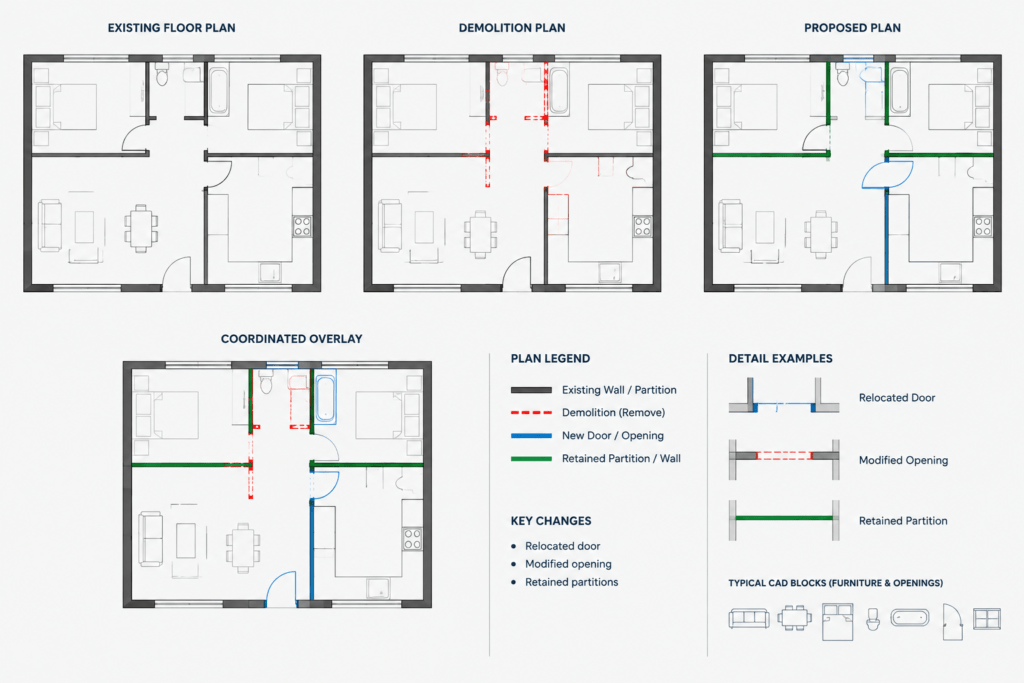
- Relocated items: Identify the item at its original location on the demolition plan and at its proposed location on the new work plan.
- Items to remain: Keep them visible in both relevant views, but do not redraw them as new construction.
- Modified openings: Show the existing opening, the portion affected by demolition, and the final configuration in their appropriate plans.
- Protected items: Identify what remains and why protection is necessary without implying a protection method that has not been specified.
- Salvaged items: Coordinate removal, storage, preparation, and reinstallation language with the project specifications.
Use Graphic Hierarchy Instead of Color Alone
Layer colors may help during drafting, but plotted drawings must remain understandable in their intended output format. Status should be communicated through a coordinated combination of lineweight, linetype, screening, symbols, notes, and drawing separation.
A common hierarchy gives new or removed work stronger visual emphasis while allowing retained existing construction to recede. The exact appearance depends on the office plot style and sheet scale. Always review a plotted or exported test rather than judging the drawing only from the model-space display.
Run a Three-Plan Coordination Check
Before issuing the drawings, compare the existing, demolition, and new work plans as a sequence. Review them both visually and by isolating relevant CAD layers.
- Every demolished object should originate from a documented existing condition.
- Every new opening should coordinate with the demolition or modification needed to create it.
- Objects marked to remain should appear consistently in later views.
- Relocated items should have a clear origin and destination.
- Room names, door identifiers, section marks, and detail references should agree across the set.
- Demolition notes should not appear on the new work plan unless intentionally repeated.
- New work dimensions should not reference construction that will be removed.
- Consultant backgrounds should align with the same architectural base and revision.
Overlay comparisons are especially useful for finding small shifts, duplicate walls, abandoned door swings, and fixtures left at both their old and new locations. The comparison is a coordination aid, not a substitute for field verification.
Keep Revisions Controlled
Renovation projects often change as concealed conditions are discovered. Update the base information carefully rather than editing only the sheet where an issue was noticed. A field change to an existing wall may affect the demolition boundary, proposed dimensions, interior elevations, ceiling plans, schedules, and consultant drawings.
Record verified changes through the project’s revision process, and avoid silently replacing surveyed geometry without documenting the reason. Clear status organization makes these updates easier because the drafter can identify whether the change belongs to the existing record, demolition scope, or proposed work.
A Clear Sequence Reduces Ambiguity
Effective existing, demolition, and new work plans tell a coordinated story: establish the known condition, identify the transformation, and present the finished design. A disciplined CAD structure supports that story by separating object status, annotation, and sheet visibility. The result is not merely a cleaner drawing file; it is a set that can be reviewed, revised, and interpreted with fewer assumptions.