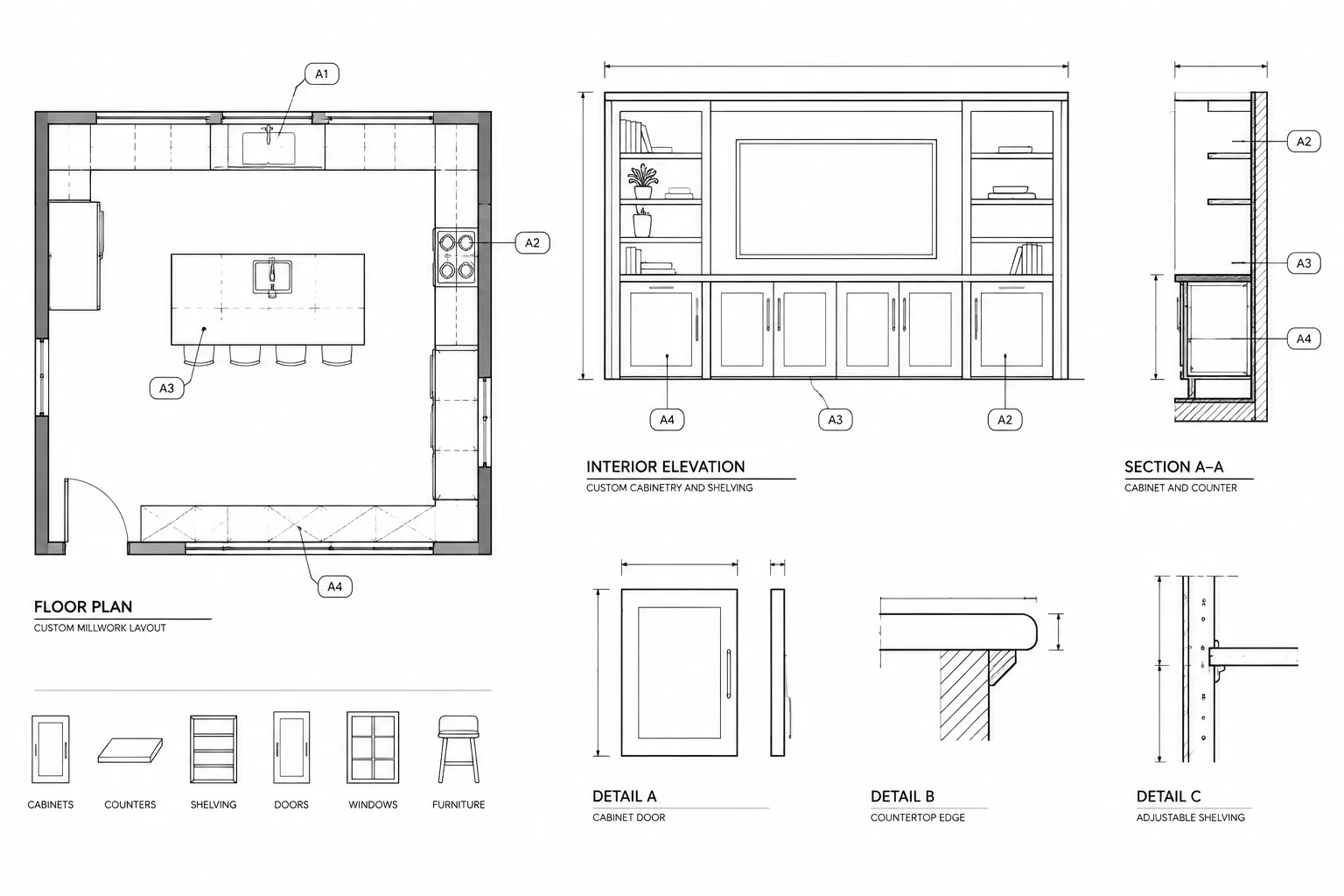
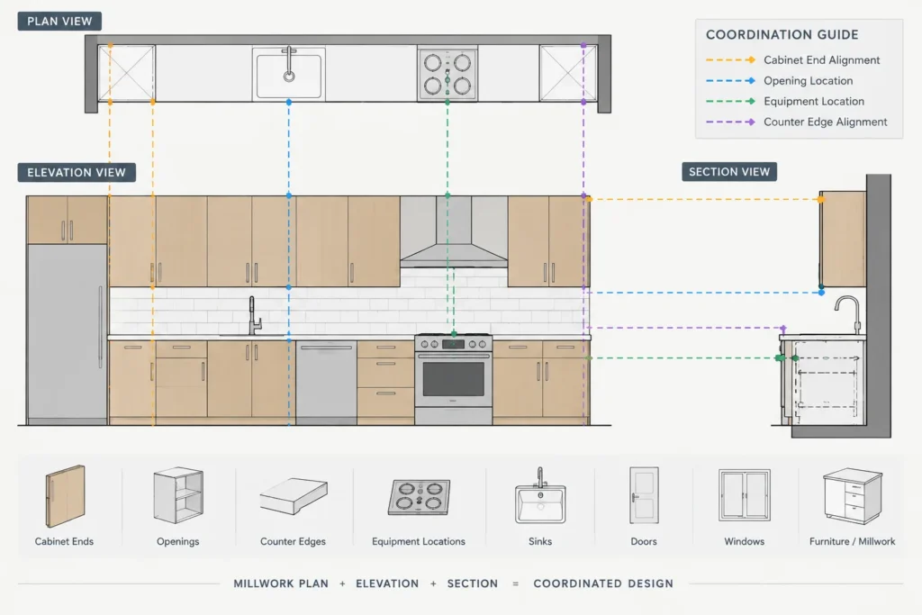
Architectural millwork can look simple on a floor plan, but it often requires close coordination across several drawing types. Cabinets, counters, reception desks, shelving, paneling, and built-in seating may appear in plans, interior elevations, sections, finish drawings, and schedules. If those views are drafted independently, inconsistencies can quickly develop.
A reliable architectural millwork CAD drafting workflow begins with coordinated reference geometry and a clear distinction between design intent and fabrication information. Architectural drawings should communicate the location, configuration, appearance, interfaces, and required clearances of the work without pretending to replace verified shop drawings or manufacturer data.
Define the Millwork Scope Before Drafting
Start by identifying what the architectural drawing set needs to communicate. The scope may include standard casework, custom cabinets, open shelving, counters, wall panels, decorative trim, or built-in furniture. It may also involve equipment, plumbing fixtures, electrical devices, and finish transitions that are documented elsewhere.
Before drawing, answer several coordination questions:
- Which elements are built-in, and which are movable furniture?
- Which items are custom millwork, manufactured casework, or owner-provided equipment?
- Where are the controlling walls, columns, openings, and floor level changes?
- Which elevations and sections are needed to explain the design?
- How will cabinet types, finishes, hardware groups, and equipment openings be identified?
- Which dimensions must be confirmed in the field or coordinated with a supplier?
This review helps prevent unnecessary drafting and makes the intended level of detail clear.
Use the Floor Plan as the Coordination Base
The floor plan should establish the millwork footprint and its relationship to the room. Reference the current architectural base rather than copying walls into an isolated drawing. If the project uses external references, attach the appropriate background and keep millwork geometry in its designated file or discipline layer structure.
Draw the overall extents first. Locate cabinet runs, islands, counters, shelving, and built-in seating from stable building references such as finished wall faces, structural grids, or established room boundaries. Avoid controlling important locations from loose furniture blocks or temporary construction lines.
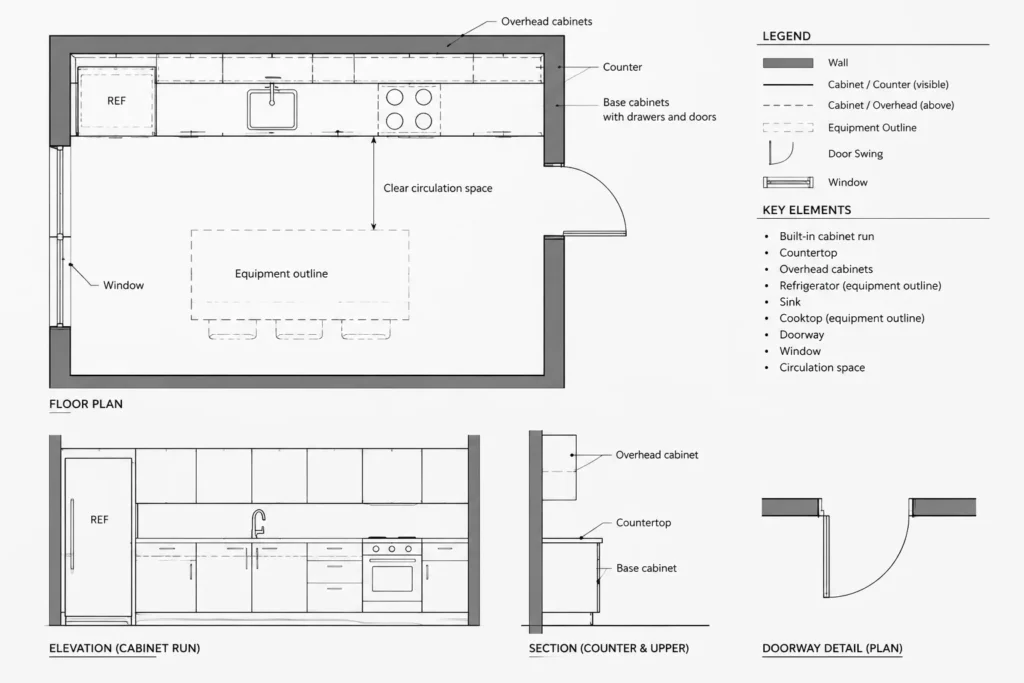
Plan graphics should make the following conditions understandable:
- Front edges and ends of cabinets or counters
- Changes in depth, alignment, or configuration
- Openings for appliances, fixtures, or equipment
- Doors, drawers, knee spaces, and accessible approach areas where applicable
- Overhead cabinets or shelves shown with an appropriate overhead convention
- Adjacent door swings, circulation paths, and service clearances
Do not overload the general floor plan with fabrication-level linework. Use enlarged plans, elevations, and sections when the configuration cannot be explained clearly at the primary plan scale.
Develop Interior Elevations from the Plan
Interior elevations should align with the millwork footprint established in plan. Project major reference points from the plan, including wall limits, cabinet ends, centerlines, openings, fixtures, and equipment. This reduces the risk of drawing a visually appealing elevation that does not fit the actual room.
Build the elevation from broad elements to fine detail:
- Establish the floor, ceiling, wall edges, and openings.
- Draw the overall counter and cabinet composition.
- Add doors, drawers, open compartments, shelving, and panels.
- Place fixtures, equipment, and devices using coordinated information.
- Add finish boundaries, tags, dimensions, and notes last.
Use lineweight and line type to separate object profiles from internal divisions, surface patterns, concealed conditions, and background elements. The outer profile and major changes in plane should generally read more strongly than door joints or finish seams.
Keep Repeated Units Consistent
Repeated cabinet fronts can be drafted as blocks when they truly share the same geometry. Blocks are useful for maintaining consistent symbols and speeding up revisions, but they should not hide meaningful differences. A cabinet with a different opening, finish, hardware condition, or adjacent interface may require a separate block definition or carefully managed instance data.
Avoid exploding blocks simply to make quick edits. Uncontrolled copies tend to drift apart over time and make global revisions difficult.
Add Sections Where Construction Relationships Matter
Plans and elevations explain arrangement, but sections reveal depth and interfaces. A section may be needed where millwork meets a wall, floor, ceiling, window, countertop, backsplash, plumbing fixture, or integrated equipment item.
Architectural millwork sections commonly clarify:
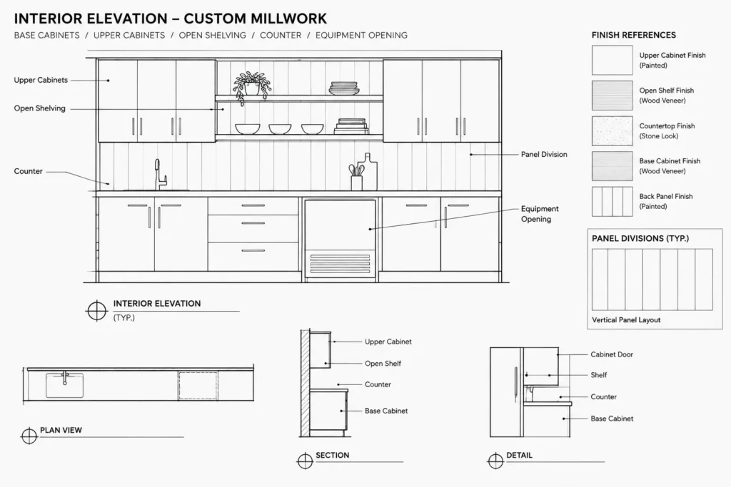
- Counter and cabinet relationships
- Recessed, flush, or projecting conditions
- Open shelving and support zones
- Wall backing or attachment coordination
- Transitions between millwork and adjacent finishes
- Service spaces required for equipment or fixtures
- Panel, reveal, trim, and edge relationships
Only show construction that has been verified or is intentionally schematic. If an attachment method, material thickness, or product assembly has not been confirmed, do not present it as resolved fabrication information. Use an appropriate note or reference to indicate that coordination is still required.
Organize Millwork Layers by Graphic Purpose
Millwork should follow the project CAD standard rather than introducing an isolated layer system. When no established standard exists, organize layers according to graphic function and drawing management needs.
| Layer purpose | Typical content | Coordination benefit |
|---|---|---|
| Primary millwork | Cabinet bodies, counters, shelving, and built-ins | Allows the main scope to be isolated and reviewed |
| Overhead elements | Upper cabinets, suspended shelves, and concealed outlines | Supports a distinct overhead graphic convention |
| Millwork annotation | Tags, notes, and identifiers | Separates descriptive information from model geometry |
| Millwork dimensions | Plan, elevation, and detail dimensions | Makes dimension visibility easier to control |
| Finish patterns | Surface hatches and material indications | Prevents dense patterns from obscuring profiles |
| Reference equipment | Appliances, fixtures, and coordinated equipment outlines | Distinguishes related items from the millwork scope |
Layer names should be treated as project-specific examples, not universal requirements. The important goal is predictable visibility, plotting, and responsibility.
Dimension from Stable References
Millwork dimensions should communicate the design without creating competing control points. Start with overall location and extents, then add subdivisions only where they are needed to explain the configuration.
Use stable references such as finished wall faces, opening edges, room centerlines, or other clearly defined architectural datums. Avoid dimensioning critical locations from hatch boundaries, annotation graphics, or unverified equipment blocks.
Coordinate dimensions among the plan, elevation, and section. A cabinet run should not have one controlling overall dimension in plan and a conflicting subdivision in elevation. Where field conditions control the final fit, identify the need for verification rather than assuming the modeled geometry is exact.
Coordinate Tags, Notes, and Schedules
Each millwork identifier should have a clear purpose. A tag may refer to a cabinet type, an elevation, a finish, a custom assembly, or a schedule entry. Do not combine unrelated meanings in one coding system unless the project documentation explains it clearly.
Where schedules are used, keep identifiers synchronized with the drawings. Useful schedule fields may include a type mark, description, location, finish reference, hardware reference, and coordination remarks. The exact fields depend on the project scope and procurement method.
General notes should address recurring requirements. Specific notes should be placed only where a unique condition occurs. Repeating the same note across multiple views increases clutter and creates more places for conflicting edits.
Coordinate Fixtures, Equipment, and Building Services
Millwork frequently surrounds sinks, appliances, displays, technology, and specialty equipment. Downloaded CAD blocks can help with early planning, but they must not be treated as verified product geometry. Check the selected equipment information before relying on its outline, connection points, ventilation zones, door movement, or service access.
Review the millwork drawings against relevant consultant information. Look for plumbing locations, electrical devices, data outlets, lighting, mechanical grilles, and other services that may conflict with cabinet interiors or finished panels. The architectural drawings should show enough information to communicate design intent while directing detailed service requirements to the appropriate coordinated documents.
Run a Cross-View Quality Check
Before issuing the drawings, compare every millwork representation rather than reviewing each sheet in isolation.
- Confirm that plan lengths and offsets agree with elevations.
- Check that section cuts pass through the intended condition.
- Verify that cabinet ends align with walls, openings, and finish transitions.
- Confirm that equipment shown in plan also appears correctly in elevation where relevant.
- Review overhead linework and concealed conditions for consistent graphics.
- Check that tags match schedules and referenced details.
- Remove duplicate lines, abandoned options, and unnecessary imported block data.
- Plot the sheets to confirm that profiles, joints, hatches, and background geometry remain legible.
Maintain Design Intent Without Over-Detailing
Good architectural millwork CAD drafting is not measured by the number of lines in the file. Its purpose is to communicate a coordinated design that can be reviewed, priced, and developed further. Plans should establish location, elevations should explain composition, sections should clarify interfaces, and schedules should organize repeated information.
When dimensions, product requirements, field conditions, or fabrication methods remain uncertain, state the required coordination instead of inventing precision. A disciplined drawing set gives fabricators and contractors a reliable architectural basis while leaving product-specific and fabrication decisions to verified submittals, shop drawings, and project requirements.