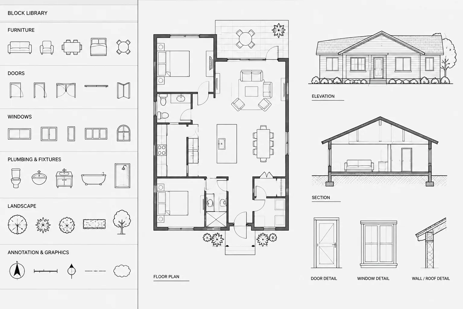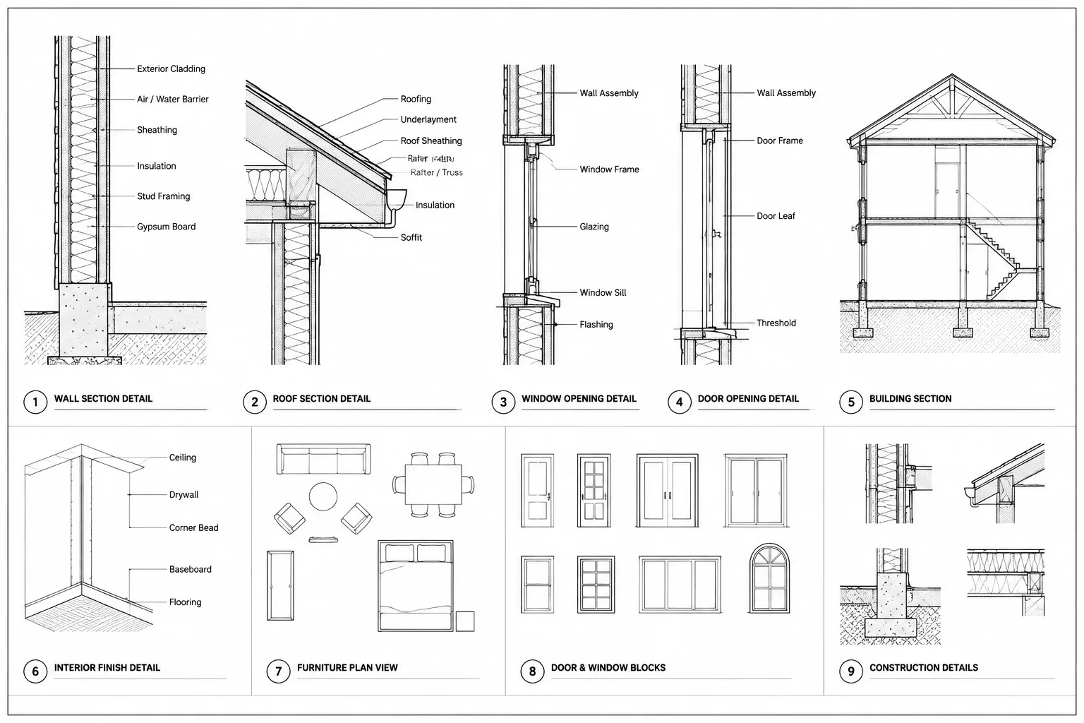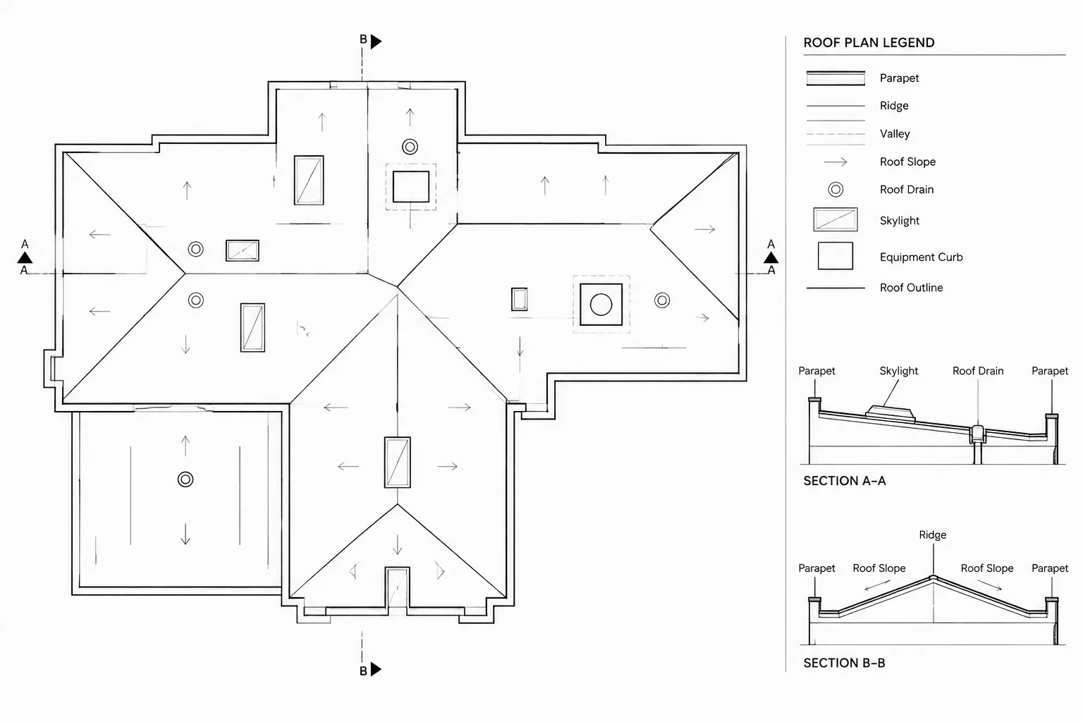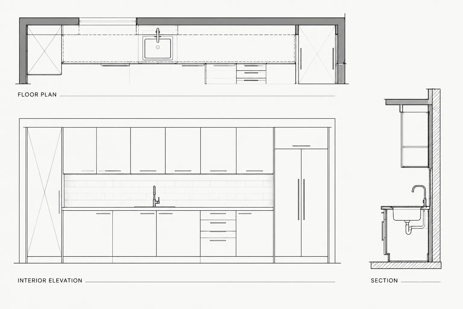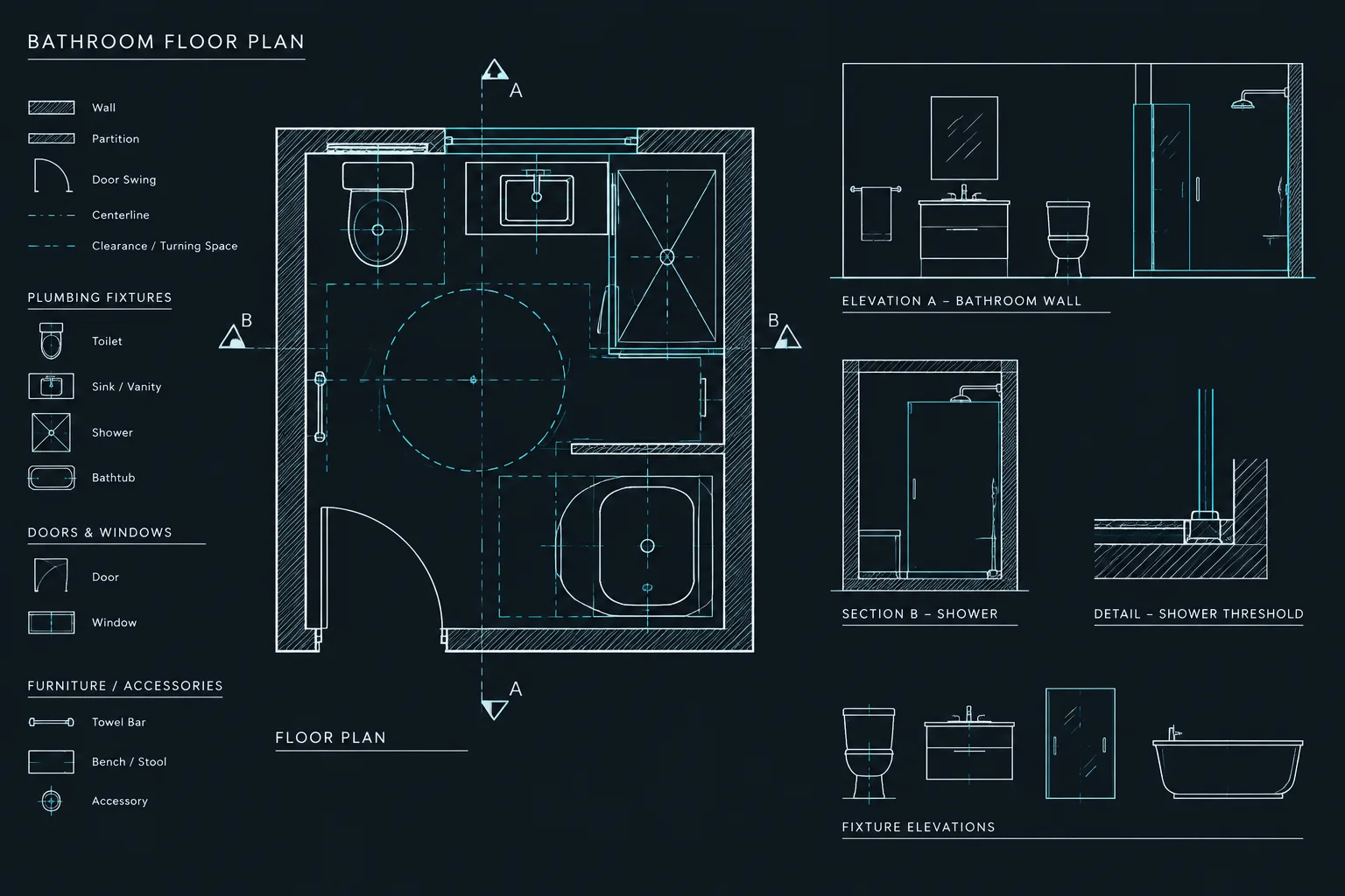
Drafting a bathroom plan in AutoCAD requires more than arranging plumbing fixture symbols inside a room. The plan must communicate buildable relationships among finished walls, openings, fixtures, accessories, service zones, floor features, and adjacent construction.
The workflow below treats the bathroom as part of a coordinated drawing set. It explains how to establish a reliable background, organize CAD information, place verified blocks, manage design checks, and connect the plan with elevations, schedules, consultant drawings, and details. Project criteria and current product information should always govern final locations and clearances.
A bathroom plan may occupy only a small part of a building, but it concentrates walls, doors, plumbing fixtures, accessories, finishes, clearances, and building systems into a limited area. Small drafting errors can therefore create significant coordination problems. A fixture block drawn at the wrong size, an unverified door swing, or a wall that does not allow enough space for concealed services can affect several drawings.
This guide explains a practical workflow for drafting and coordinating a bathroom plan in AutoCAD. It focuses on drawing organization and design communication rather than prescribing dimensions. Required clearances, mounting locations, accessibility provisions, fixture specifications, and construction details must be verified against the project criteria, applicable regulations, consultant information, and selected products.
Collect the Required Information Before Drafting
Begin with the current architectural background rather than an isolated bathroom sketch. Confirm that the wall layout, structural grid, floor levels, shafts, and adjoining rooms come from the latest coordinated files. A bathroom cannot be planned reliably without understanding what surrounds it.
Useful source information may include:
- The current architectural floor plan and wall types
- Plumbing fixture selections or preliminary fixture types
- Plumbing consultant backgrounds showing connections, risers, and drains
- Structural drawings showing slabs, beams, columns, and openings
- Mechanical information affecting exhaust or ceiling space
- Electrical information for lighting, controls, receptacles, and equipment
- Interior finish requirements and tile layout intent
- Accessibility and project-specific clearance criteria
Record unresolved items rather than filling gaps with assumptions. A clear placeholder note or coordination marker is safer than presenting guessed information as final.
Establish a Controlled CAD Background
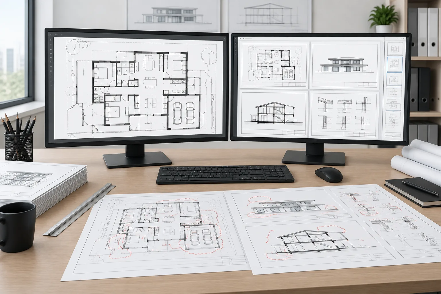
Use an external reference for the main architectural plan when the project workflow permits it. This keeps the bathroom drawing connected to the current building geometry and reduces duplicate wall linework. If consultant files are referenced, place them on distinguishable layers and control their display so they support coordination without overwhelming the architectural plan.
Before placing fixtures, verify the drawing units and confirm the scale of at least one known element. Inspect the location and orientation of the bathroom relative to the larger floor plan. Avoid scaling a reference merely because it appears too large or small on screen; display size is not evidence of incorrect geometry.
Draft Walls, Openings, and Fixed Boundaries First
Lay out the room enclosure before adding fixtures. Draw or reference the finished faces of walls clearly because clearances and fixture positions are usually coordinated to finished surfaces, not vague wall centerlines. Identify wall thicknesses, furring, tile build-ups, plumbing chases, and shaft boundaries where they affect usable space.
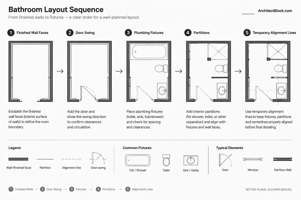
Add doors and other openings early. Show the actual door leaf and swing direction rather than a generic opening. Check the swing against fixtures, partitions, grab-bar zones, accessories, and circulation paths. Where a sliding or specialized door is proposed, verify its pocket, track, hardware, and maintenance implications instead of treating it as a swing-door substitute with no spatial consequences.
Use Verified Fixture Blocks
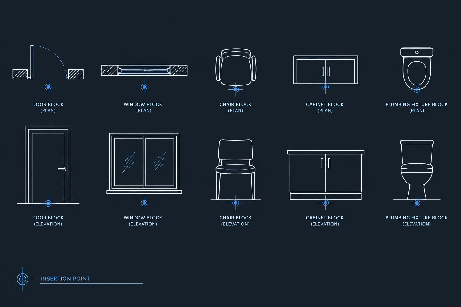
Insert plumbing fixtures as consistently organized CAD blocks. Each block should have a logical base point, correct drawing units, controlled layers, and a simple plan representation suited to the intended drawing scale. Excessive product detail can make a small bathroom plan difficult to read and can increase file size unnecessarily.
A useful fixture block may include:
- A clear fixture outline
- A centerline or connection reference where appropriate
- An insertion point related to a wall, centerline, or connection
- Optional clearance geometry on a non-plotting coordination layer
- Attributes or identification data if the office workflow uses them
Do not assume that a downloaded block represents the selected product accurately. Compare its overall geometry and connection logic with current manufacturer information or the project fixture schedule. Replace or revise generic blocks when product selection becomes more definite.
Place Fixtures by Relationships, Not Appearance
A fixture should not be positioned simply because the plan looks balanced. Locate it using intentional relationships to walls, partitions, centerlines, supply and waste locations, and required use zones. Temporary construction lines can help establish alignments without adding permanent clutter.
For each fixture, consider:
- Its relationship to the finished wall face
- The position of plumbing connections and concealed supports
- Access for use, cleaning, maintenance, and replacement
- Conflicts with door swings and adjacent fixtures
- Coordination with mirrors, dispensers, rails, and other accessories
- Whether the fixture affects slab openings or floor depressions
Keep clearance outlines visually separate from permanent architectural geometry. A dedicated non-plotting layer or a controlled coordination layer allows the team to check overlaps without printing every clearance boundary on the issued plan.
Coordinate Partitions, Chases, and Concealed Services
Plumbing walls often carry more information than their plan outline suggests. They may need to accommodate piping, carriers, valves, insulation, supports, and access requirements. Coordinate the proposed wall or chase with the plumbing consultant before treating its thickness as settled.
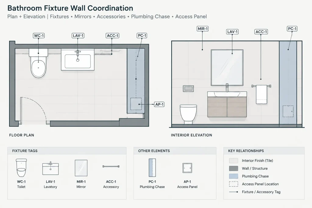
Back-to-back fixtures deserve particular attention because their centerlines and connections may not align as simply as a schematic plan implies. Likewise, a fixture shown against a structural wall may require a separate service zone. Flag these conditions for review rather than forcing all services into a nominal partition.
Access panels should be coordinated with tile joints, casework, mirrors, and accessories. Show them on the drawing where they affect the architectural finish or require a specific accessible location.
Add Accessories as Coordinated Elements
Bathroom accessories are often added late, but they can conflict with fixture use zones, doors, wall framing, and each other. Place relevant accessories in plan and use interior elevations to communicate vertical relationships that the plan cannot show clearly.
Depending on the room, coordinated items may include mirrors, dispensers, hooks, shelves, rails, waste receptacles, changing equipment, hand dryers, or sanitary-product accessories. Use distinct symbols or simplified outlines so they remain legible. Where an item is owner-furnished or selected by another party, identify that responsibility through the project’s established notation system.
Coordinate the Floor and Ceiling
The bathroom plan should be checked against both the floor construction and the reflected ceiling plan. Floor drains, slopes, waterproofing extents, finish transitions, curbs, and depressed slab areas may affect architectural and structural drawings. Their exact design should come from verified project requirements rather than a generic bathroom detail.
At the ceiling, coordinate light fixtures, exhaust grilles, sprinklers, access panels, ceiling joints, and full-height partitions. A centered ceiling device may conflict with a partition, shower enclosure, or other service. Compare the floor plan and reflected ceiling plan using the same reference origin so discrepancies are easy to identify.
Dimension the Bathroom for Construction
Dimension the information needed to establish the room and locate critical elements. Avoid dimensioning every visible line. Over-dimensioning can introduce contradictions, while under-dimensioning leaves installers to infer important relationships.
A bathroom plan commonly benefits from dimensions that establish:
- Room boundaries and partition locations
- Door openings where not controlled elsewhere
- Fixture centerlines or critical offsets
- Chase and shaft limits
- Floor openings, drains, curbs, or recesses when applicable
- Important clearances that require explicit verification
Use associative dimensions when they fit the office workflow, and place dimensions on dedicated layers. Dimension to stable references such as finished wall faces, structural grids, or other clearly defined construction points. Do not mix rough framing, finish faces, and fixture edges in one chain without making the reference basis clear.
Connect the Plan to Elevations, Schedules, and Details
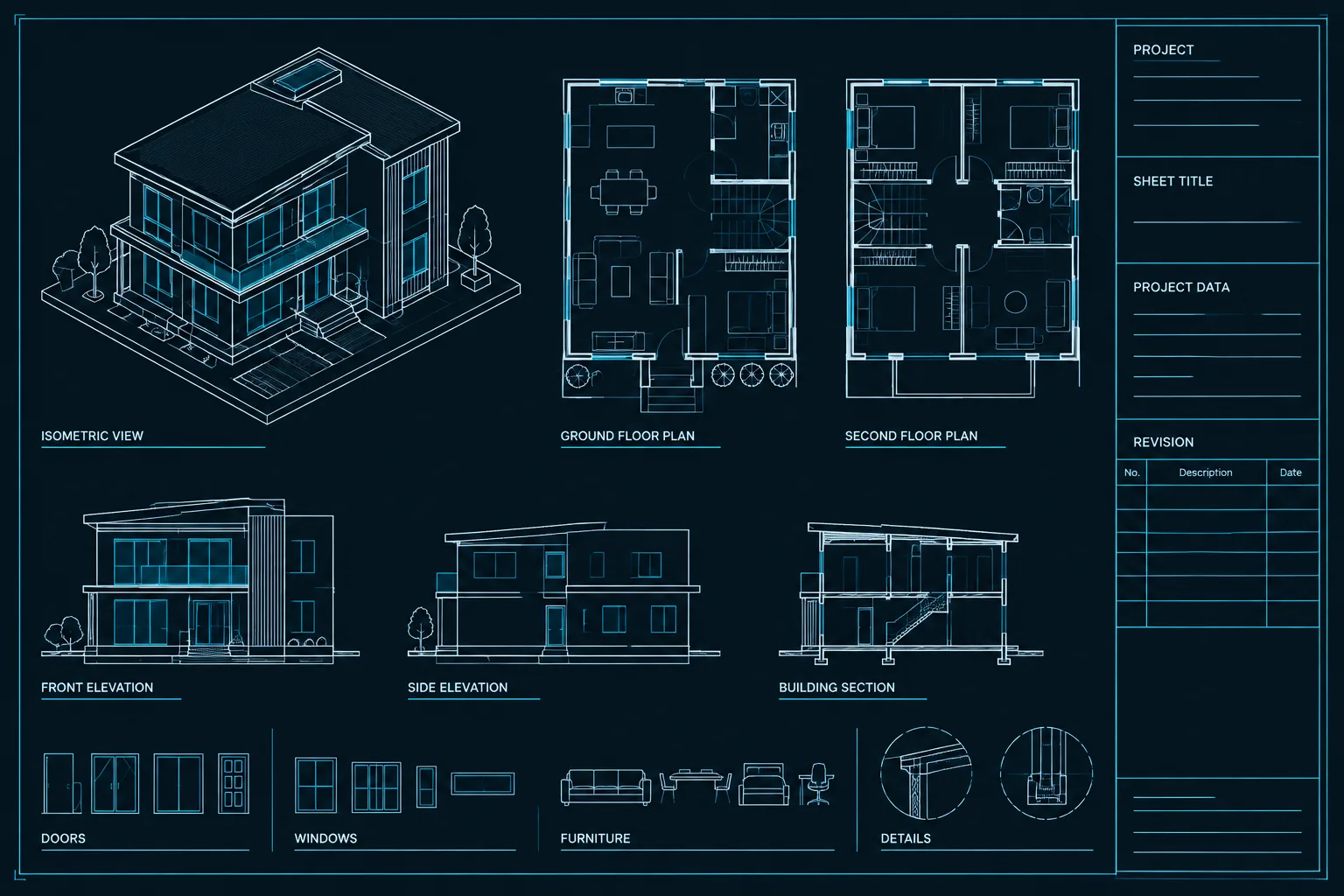
A floor plan cannot communicate every bathroom condition. Interior elevations are typically better for mounting relationships, wall finishes, mirrors, accessories, tile patterns, and vertical fixture coordination. Sections or details may be needed for curbs, floor transitions, recessed items, waterproofing interfaces, or unusual wall construction.
Use consistent fixture tags and room identification across plans, elevations, schedules, and specifications. If a fixture type changes, search for every occurrence rather than updating only the schedule. Callout symbols should direct readers to the correct view and sheet without relying on proximity alone.
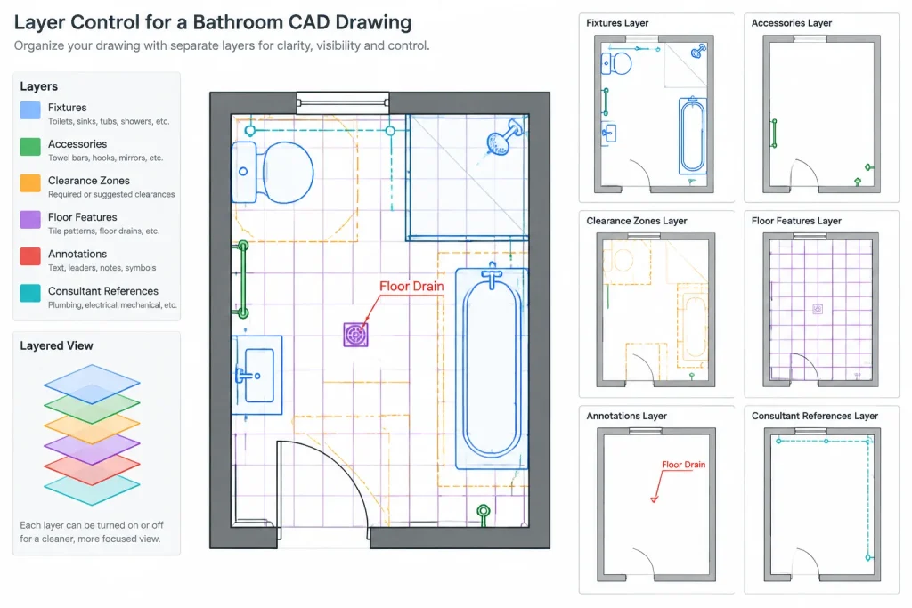
Recommended Layer Separation
| Information | Layer purpose | Coordination benefit |
|---|---|---|
| Plumbing fixtures | Primary fixture outlines and tags | Allows fixtures to be isolated and checked |
| Accessories | Wall-mounted and floor-mounted accessory graphics | Separates accessory coordination from fixture geometry |
| Clearance zones | Non-plotting or controlled-use boundaries | Makes overlaps visible during design review |
| Floor features | Drains, slopes, curbs, recesses, and transitions | Supports structural and finish coordination |
| Annotations | Notes, tags, dimensions, and callouts | Improves viewport and scale control |
| Consultant references | Referenced service information | Permits clear display control without editing source files |
Actual layer names should follow the project or office CAD standard. The important principle is to separate information by purpose rather than placing the entire bathroom on one layer.
Run a Focused Quality-Control Review
Review the bathroom at the intended plotted scale, not only while zoomed in. A technically complete plan can still fail if tags overlap, fixtures merge into wall poche, or clearance lines dominate the sheet.
Before issue, check that:
- The plan uses the current architectural and consultant backgrounds
- Fixture blocks are correctly scaled and represent the intended types
- Doors do not conflict with fixtures, partitions, or accessories
- Clearance criteria have been verified for the project
- Wall and chase depths have been coordinated with concealed services
- Floor drains, slopes, openings, and transitions agree with related drawings
- Ceiling devices align with the room layout and partition conditions
- Fixture tags match schedules, elevations, and details
- Dimensions reference clear and consistent construction points
- Unresolved decisions are visibly identified rather than concealed
A well-drafted bathroom plan is more than an arrangement of fixture symbols. It is a coordinated record of spatial, architectural, plumbing, structural, electrical, finish, and accessibility decisions. Building the plan in a deliberate sequence—and checking it against related views—produces a clearer DWG file and reduces avoidable conflicts during documentation and construction.
Use the Bathroom Plan as a Coordination View
A useful bathroom plan distinguishes between confirmed geometry, reference information, and unresolved design decisions. Architectural elements should remain readable, consultant backgrounds should be visually controlled, and temporary checking graphics should not be confused with construction information.
Assign clear ownership to each type of information. The architectural plan may establish partitions, openings, finishes, fixture locations, and tags, while consultant drawings define service routing and connections. Coordination does not mean copying every consultant line into the architectural file. It means comparing the information, identifying conflicts, and documenting the agreed design consistently.
Manage Revisions Deliberately
Bathroom changes often affect more than the floor plan. Moving a fixture may alter plumbing connections, accessory positions, wall supports, finish layouts, ceiling coordination, dimensions, interior elevations, and schedule references. Treat each revision as a change that must be traced through related views.
A practical review sequence is to isolate the changed area, compare it with the current references, update dependent architectural information, and then inspect the plotted result. If an issue remains unresolved, use the project’s established coordination notation rather than silently choosing a condition that has not been approved.
Keep the DWG Readable for Other Users
Drawing quality includes file usability. Use consistent block definitions, meaningful layer separation, controlled linework, and annotations that remain clear at the intended output scale. Remove abandoned test geometry and avoid embedding unnecessary detail in fixture blocks.
Before sharing the file, confirm that referenced information resolves correctly and that important geometry has not been hidden by display settings. A clean bathroom plan should allow another team member to understand what is fixed, what is referenced, and what still requires coordination.
Frequently Asked Questions
Should bathroom fixtures be drawn directly or inserted as blocks?
Blocks are generally easier to manage when fixtures repeat or require coordinated updates. Each block should use the correct drawing units, a predictable insertion point, suitable layer behavior, and geometry verified against the selected fixture or current project information.
Why should clearance outlines be separated from fixture graphics?
Clearance outlines serve a checking purpose and may not belong on the final plotted plan. Keeping them on a controlled coordination layer helps reviewers identify overlaps without confusing those boundaries with walls, fixtures, or finish lines.
What should be checked when a bathroom door changes?
Review the leaf and swing against fixtures, accessories, partitions, circulation, and required use areas. Also check connected elevations, hardware information, wall conditions, and any nearby controls or equipment affected by the revised opening.
How should consultant backgrounds appear in the architectural drawing?
They should be distinguishable from primary architectural information and controlled so they support review without dominating the plan. Do not edit a consultant reference as a substitute for requesting or documenting a coordinated change.
When is an interior elevation needed?
An interior elevation is useful when vertical relationships cannot be communicated clearly in plan. Typical subjects include mirrors, accessories, wall finishes, tile intent, recessed items, controls, and alignment between wall-mounted elements.
How can bathroom plan revisions be checked efficiently?
Identify every drawing element connected to the change, including tags, dimensions, schedules, elevations, details, floor features, ceiling items, and consultant information. Review the updated plan at its intended plotted scale after the coordination check.