Coordinate problems in DWG files are rarely solved by moving a reference until it looks correct. Reliable coordination begins with an agreed architectural CAD project origin, a known orientation, and a repeatable method for checking incoming and outgoing files.
This guide explains how to distinguish drawing zero from project control, choose between local and survey-based coordinates, manage xrefs, and document the relationship for the wider design team. Use the workflow as a coordination framework, then adapt it to the verified survey information, consultant requirements, and CAD standards established for the project.
A reliable project origin allows architectural plans, site information, and consultant drawings to align without repeated manual adjustment. When that origin is unclear, teams often compensate by moving references, rotating backgrounds, or creating separate “fixed” copies. Those quick corrections can eventually produce conflicting coordinates and unreliable drawing exchanges.
An architectural CAD project origin does not need to be complicated, but it must be intentional. The team should know what point controls alignment, whether the building is using local or surveyed coordinates, and how files are expected to behave when referenced together.
What Is a Project Origin in Architectural CAD?
The drawing origin is the zero coordinate of a CAD file. A project origin is the agreed reference point used to coordinate project geometry across multiple files. The two may be the same, but they are not automatically equivalent.
For a small architectural plan, the project origin might be a selected grid intersection or a stable corner of the building. For a site-coordinated project, the controlling information may come from a survey or civil base. The most important requirement is consistency: every participating file must either use the shared coordinates directly or follow a documented insertion and rotation procedure.
| Term | Practical meaning | Coordination role |
|---|---|---|
| Drawing origin | The zero coordinate stored in the DWG environment | Provides the file’s fundamental coordinate reference |
| Project origin | The agreed control point for project alignment | Allows architectural and consultant files to register consistently |
| Local coordinates | A simplified coordinate system centered near the building | Makes building drafting and coordinate checking easier |
| Survey coordinates | Coordinates supplied through verified site or survey information | Relates project geometry to broader site control |
| Control marker | A clearly identified point or symbol used to verify alignment | Provides a visible check when files are referenced together |
Choose a Coordinate Strategy Before Files Multiply
The best time to establish the origin is near the start of drawing production. Changing it after plans, elevations, details, consultant backgrounds, and sheets have been developed creates avoidable risk.
Two broad strategies are common.
Local building coordinates
A local system places the building near the drawing origin and uses an easily recognized architectural control point. This can simplify day-to-day drafting, especially when the project is focused on one building and does not require direct drafting in survey coordinates.
The local point should be stable. A temporary partition corner, landscape edge, or design element likely to move is a poor choice. A major grid intersection or another intentionally preserved control point is usually easier to maintain.
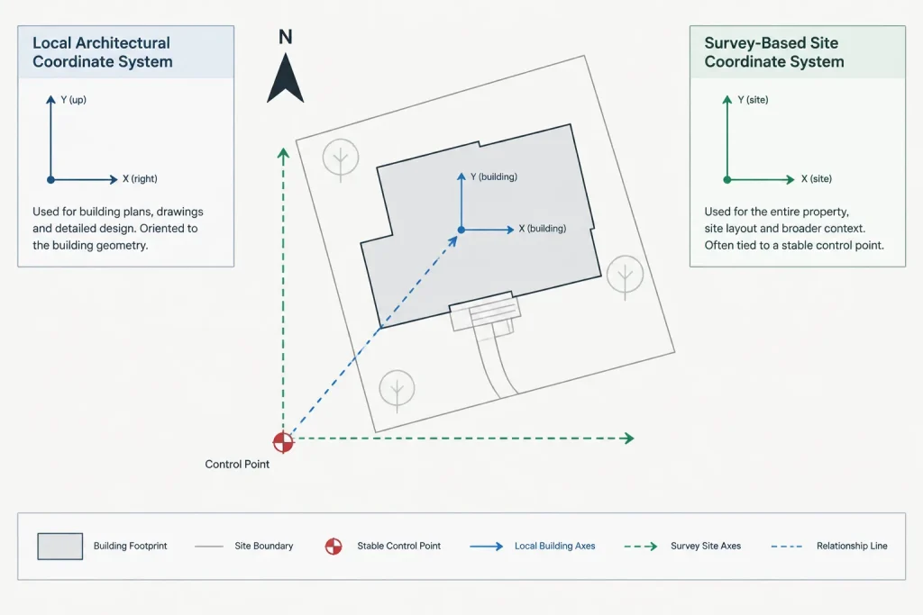
Survey-based coordinates
A site-driven project may need to coordinate with verified survey or civil information. In that case, the survey file should be treated as controlled source material rather than casually moved to suit the architectural plan.
Survey-based geometry can be located far from the drawing origin or use an orientation that is inconvenient for building drafting. The team may therefore maintain a local architectural working arrangement while preserving a documented relationship to the survey coordinates. That relationship must be tested and communicated rather than reconstructed from memory during each exchange.
A Practical Setup Workflow
1. Identify the controlling source
Determine which file or discipline establishes the authoritative site position. Do not assume that an early planning diagram, imported PDF, or preliminary base contains verified coordinate information. Confirm the source and record its file status.
2. Select stable control points
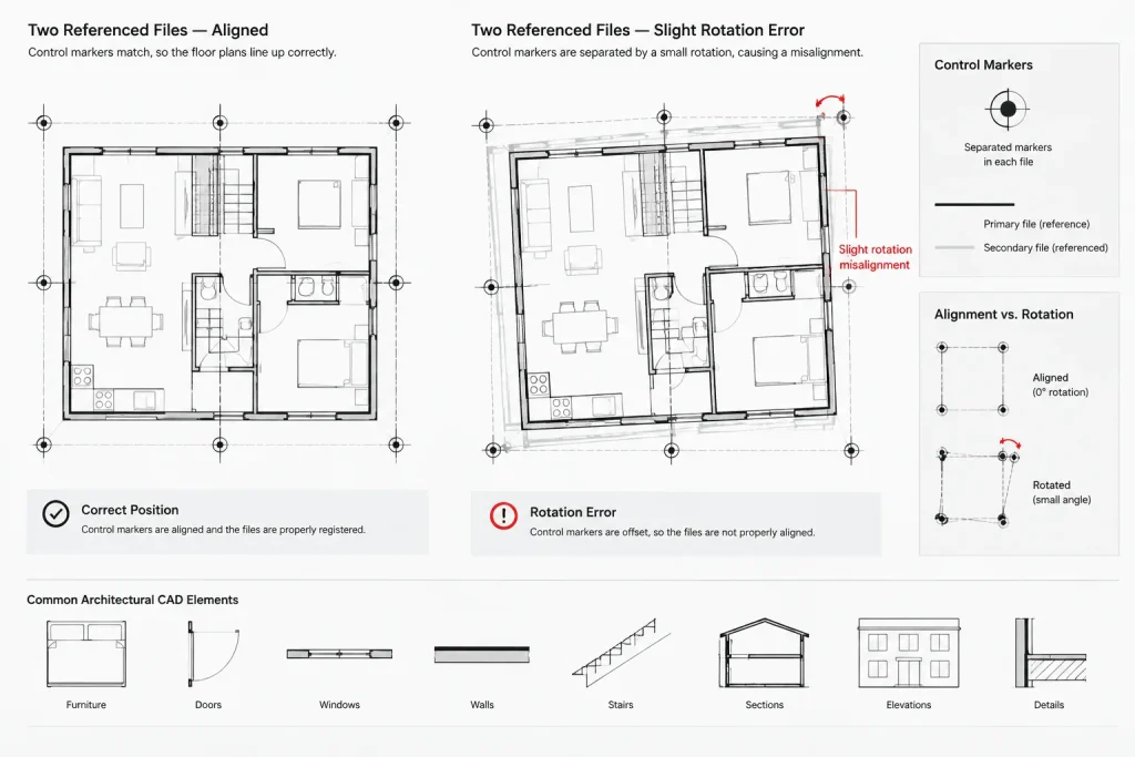
Use at least one clearly identifiable point for position and another reference for orientation. A single point can confirm that two files share a location, but it cannot by itself reveal an incorrect rotation.
Control graphics should be easy to inspect without becoming part of the plotted architectural presentation. Place them on a dedicated coordination layer with an understandable name and controlled plotting behavior.
3. Record the orientation
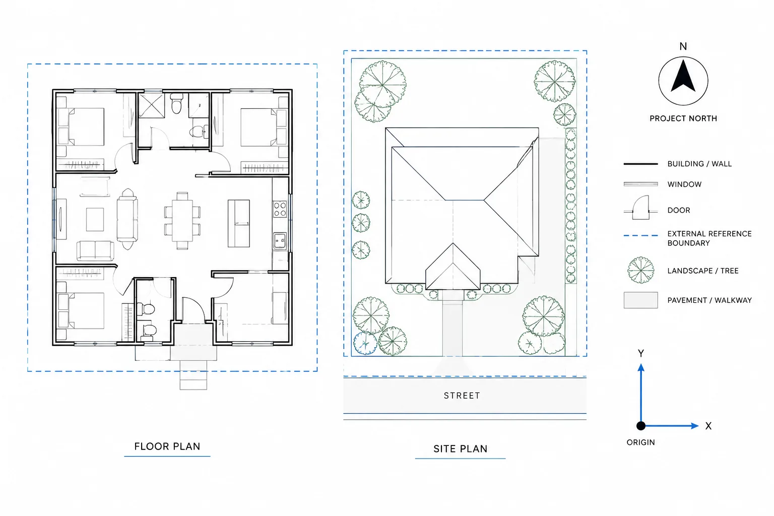
Document how the architectural plan is oriented relative to the controlling site information. Project north, true north, and a rotated working view are different concepts. Rotating a view for convenient drafting does not necessarily change the actual geometry or its coordinate relationship.
If a user coordinate system is used for drafting convenience, label and manage it carefully. Team members should not mistake a changed coordinate display for a relocated project.
4. Test the reference relationship
Attach the architectural and site files into a clean coordination drawing. Use the intended insertion point, scale, and rotation rather than dragging the reference into place visually. Inspect the control markers and several physical features distributed across the project.
A check near only one corner can hide a rotation or scale problem. Review points on opposite sides of the building or site to make misalignment easier to detect.
5. Protect the approved geometry
Once alignment has been verified, avoid moving the primary model merely to improve sheet composition. Paper-space viewports, view rotation, and drawing organization methods should handle presentation needs without changing the coordinated model position.
If geometry must be relocated because the agreed project system has changed, treat the move as a controlled project-wide revision. Identify affected references, backgrounds, exported files, and consultant deliverables before making the change.
6. Create an origin note
Add a short project-specific coordinate note to the CAD standards, file index, transmittal information, or readme documentation. It should explain:
- Which file controls the project coordinates
- Whether the architectural files use local or survey-based coordinates
- Which point is used as the architectural control point
- How project orientation is established
- Whether references should be inserted using shared coordinates or a documented transformation
- Which layers contain nonplotting control graphics
- Who should be contacted before geometry is moved
Using Xrefs Without Losing Coordinate Control
External references are most reliable when files already share a deliberate coordinate relationship. Repeatedly moving an xref into place creates a transform that exists only in the host drawing. Another team member attaching the same source may not reproduce that adjustment.
When a transform is necessary, document it and keep the source file unchanged. Do not create multiple vaguely named copies with slightly different locations. A coordination drawing can serve as a useful testing environment, but it should not become the only place where the alignment logic is understood.
After receiving a revised consultant file, reload or replace it in the test environment and confirm the control points again. A filename that has not changed does not guarantee that the internal geometry remains at the same coordinates.
Common Project-Origin Problems
Moving the building to fit a title block
Model geometry should not be repositioned to fit a sheet border. This breaks established reference relationships and can shift dimensions, annotations, or linked discipline files. Compose the sheet with viewports instead.
Using an unstable design feature as the origin
A façade corner or interior partition may move during design. If that feature is the undocumented project origin, users may incorrectly move the entire model when the design changes. Use a deliberate control point that remains conceptually stable.
Aligning files by eye
Visual alignment may appear correct at one location while concealing rotation, scale, or unit problems elsewhere. Use coordinate inquiry tools and distributed verification points.
Confusing view rotation with geometry rotation
A plan can be displayed horizontally on a sheet without rotating the project model. Before rotating geometry, determine whether the apparent problem is only a view or user-coordinate setting.
Stripping control information from outgoing files
Consultant backgrounds should be clean, but they still need enough information to preserve alignment. Retain agreed control markers or provide clear coordinate instructions with the issued files.
Multi-Building and Campus Projects
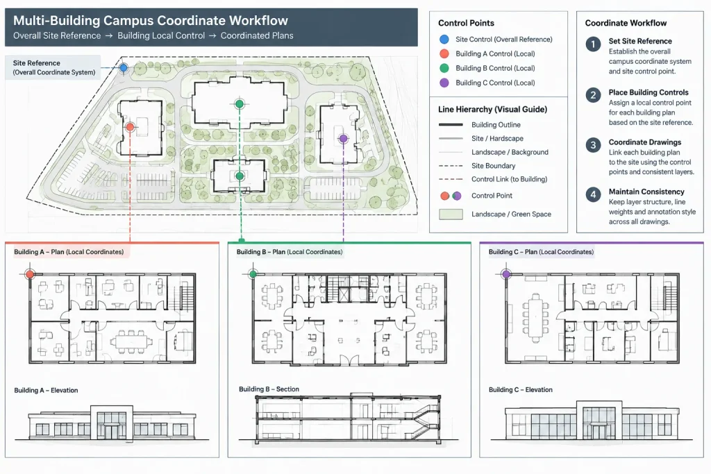
Large sites may benefit from a site-level coordinate system plus documented local controls for individual buildings. Each building file can remain practical to draft while maintaining a verifiable relationship to the overall site.
Do not assume that every building uses the same local zero point or orientation. Give each control system an unambiguous identifier and maintain a coordination file showing how the building references relate to the site base. Test complete building extents rather than checking only a shared entrance, grid line, or property feature.
Project-Origin Quality-Control Checklist
- Confirm the authoritative source of coordinate information.
- Verify drawing units before diagnosing an alignment problem.
- Check insertion point, scale, and rotation for every reference.
- Compare at least two separated control locations.
- Distinguish project orientation from viewport or user-coordinate rotation.
- Keep control graphics on dedicated, clearly named layers.
- Avoid unexplained manual movement of consultant backgrounds.
- Retest alignment when a replacement file is received.
- Document any required coordinate transformation.
- Include origin instructions when issuing DWG backgrounds.
A Stable Origin Is a Project Asset
A well-managed architectural CAD project origin reduces repetitive setup and makes drawing discrepancies easier to diagnose. It also gives architects, civil teams, structural consultants, and MEP consultants a common basis for exchanging files.
The goal is not to force every project into one coordinate method. It is to choose a method appropriate to the project, verify it with visible controls, and prevent individual files from drifting away from the agreed relationship. Once established, the origin should be treated as controlled project information—not as geometry that can be moved whenever a drawing is inconvenient to view.
Turn the Coordinate Strategy Into a Handoff Procedure
An origin strategy is most useful when another CAD user can apply it without relying on verbal history. Before issuing a background, review the file as though the recipient has no prior knowledge of its setup. The control point, orientation, reference method, units, and status of the source information should be understandable from the accompanying project documentation.
A practical handoff record can identify the controlling file, describe whether the DWG uses local or survey-based coordinates, name the coordination layers, and explain any required transformation. It should also distinguish approved coordinate information from temporary backgrounds or design studies.
Diagnose Misalignment Before Moving Geometry
When files fail to align, preserve the received files and investigate the relationship in a separate coordination drawing. Check drawing units, insertion behavior, reference scale, rotation, control markers, and the coordinate system currently being displayed. This separates a genuine geometry shift from a view, unit, or attachment problem.
Compare recognizable features across the project extent rather than checking only one convenient location. If one control location aligns while another does not, the issue may involve orientation, scale, or changed source geometry. If the entire reference is displaced consistently, investigate the insertion method and documented transformation before editing the source.
Keep an Audit Trail for Coordinate Changes
If the project coordinate relationship changes, record what changed, why it changed, which file authorized the revision, and which issued backgrounds may be affected. Clear revision notes help prevent an older reference from being reintroduced under the previous alignment method.
The strongest workflow combines stable geometry with simple documentation. Control markers make alignment visible, a coordination drawing provides a safe testing location, and an origin note allows future team members to reproduce the intended relationship.
Frequently Asked Questions
Is the DWG drawing origin always the project origin?
No. The drawing origin is the file’s zero coordinate, while the project origin is the agreed control point used for coordination. They may coincide, but the relationship should be confirmed rather than assumed.
Should an architectural model be moved to match a survey file?
Not without an approved coordinate strategy. First verify the survey source, drawing units, orientation, and required reference method. If a transformation is necessary, document it and apply it consistently without casually altering controlled source geometry.
Why can an xref look correct but still be incorrectly coordinated?
A reference can appear aligned near one feature while carrying an incorrect rotation, scale, or insertion transform. Check distributed control locations and inspect the attachment settings instead of relying only on visual alignment.
Can the plan be rotated for sheet presentation without changing project coordinates?
Yes. Drawing presentation and model coordinates are separate concerns. Viewports, working views, or managed user-coordinate settings can improve readability without relocating the coordinated model geometry.
What should accompany an issued DWG background?
Provide enough information for the recipient to reproduce the intended alignment. This may include the controlling file, coordinate approach, control-point identity, orientation method, coordination-layer names, and any documented insertion or transformation procedure.
What should be checked when a revised consultant file arrives?
Test the replacement in a coordination environment and recheck units, insertion point, scale, rotation, control markers, and recognizable project features. A familiar filename does not prove that the internal geometry retained its previous position.