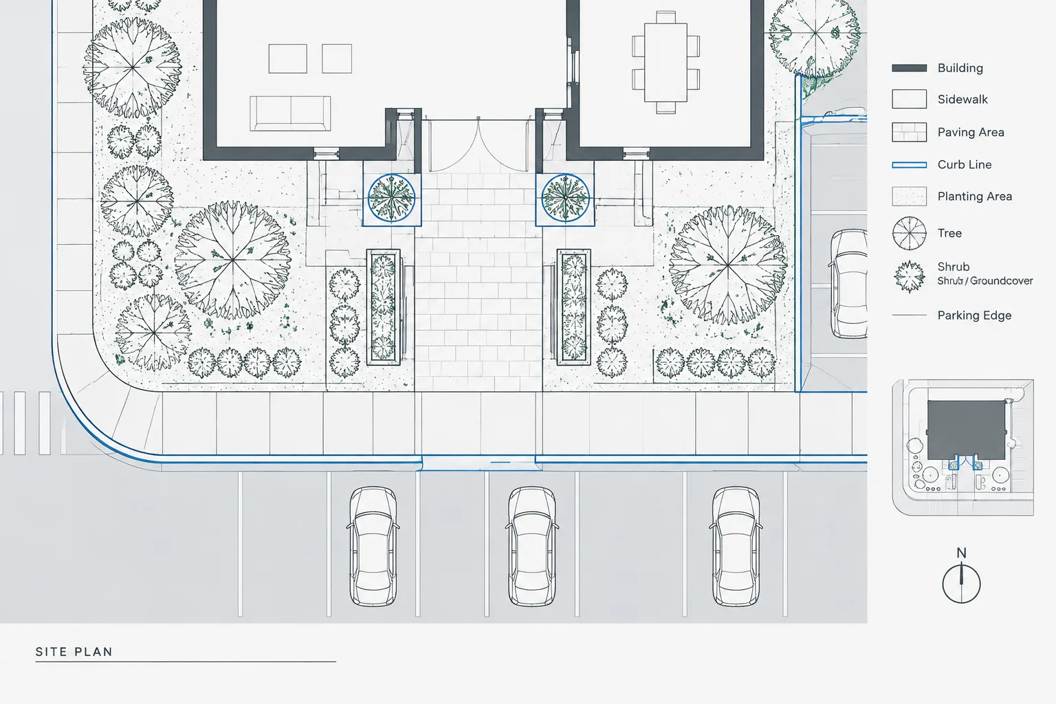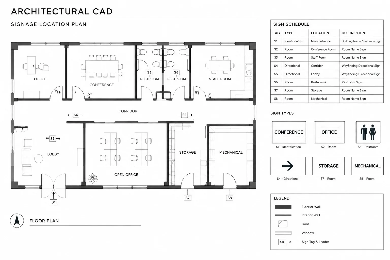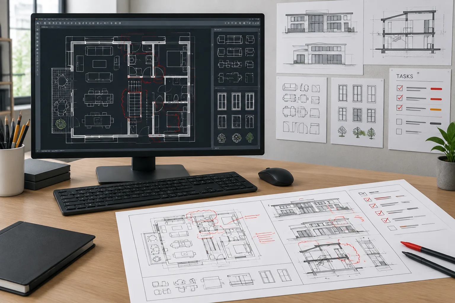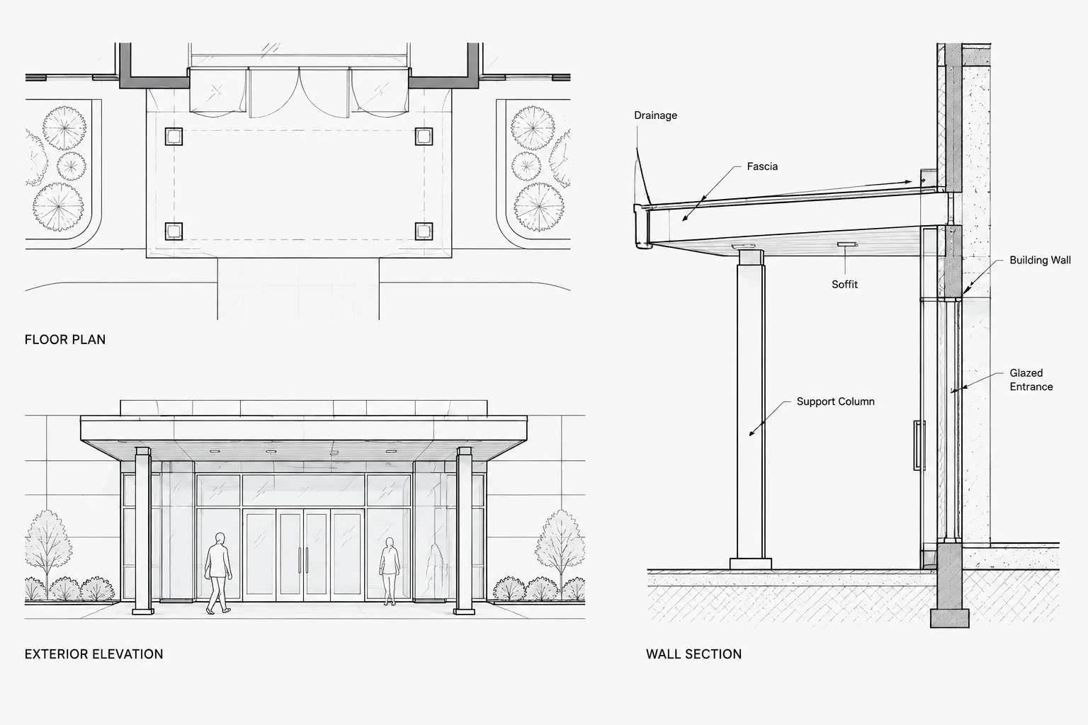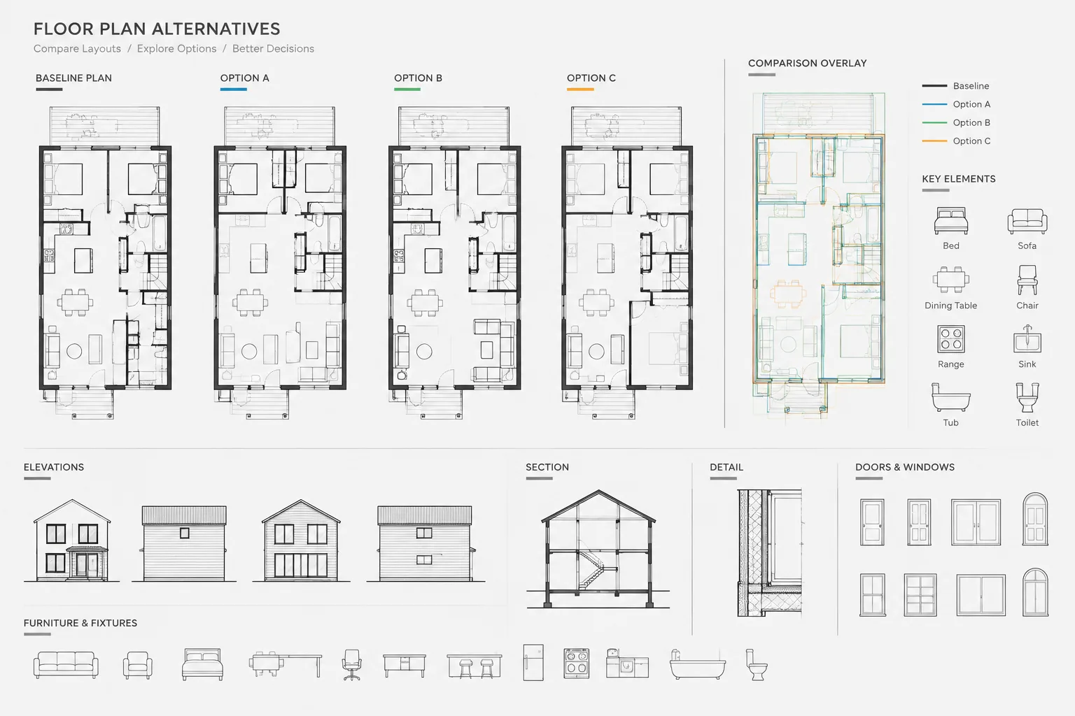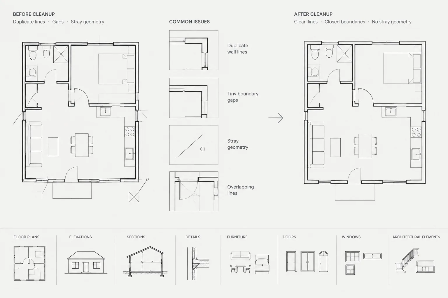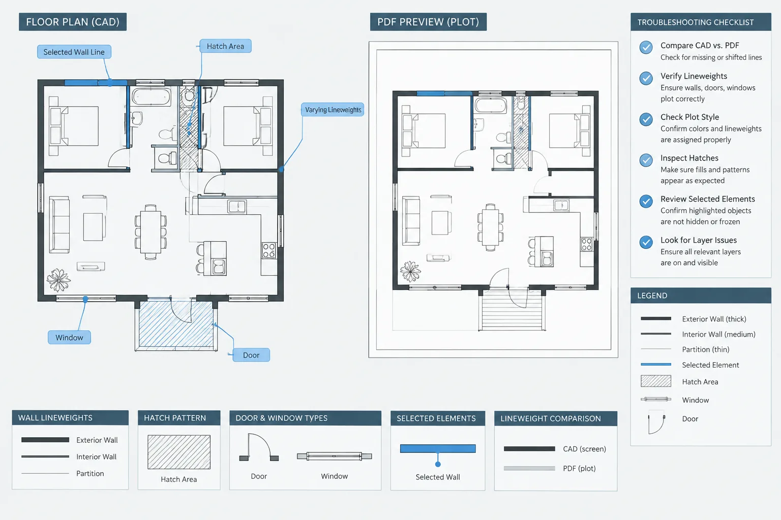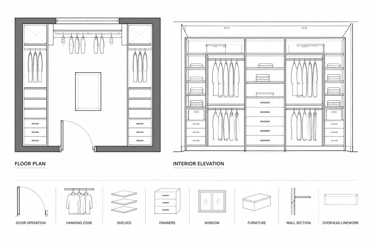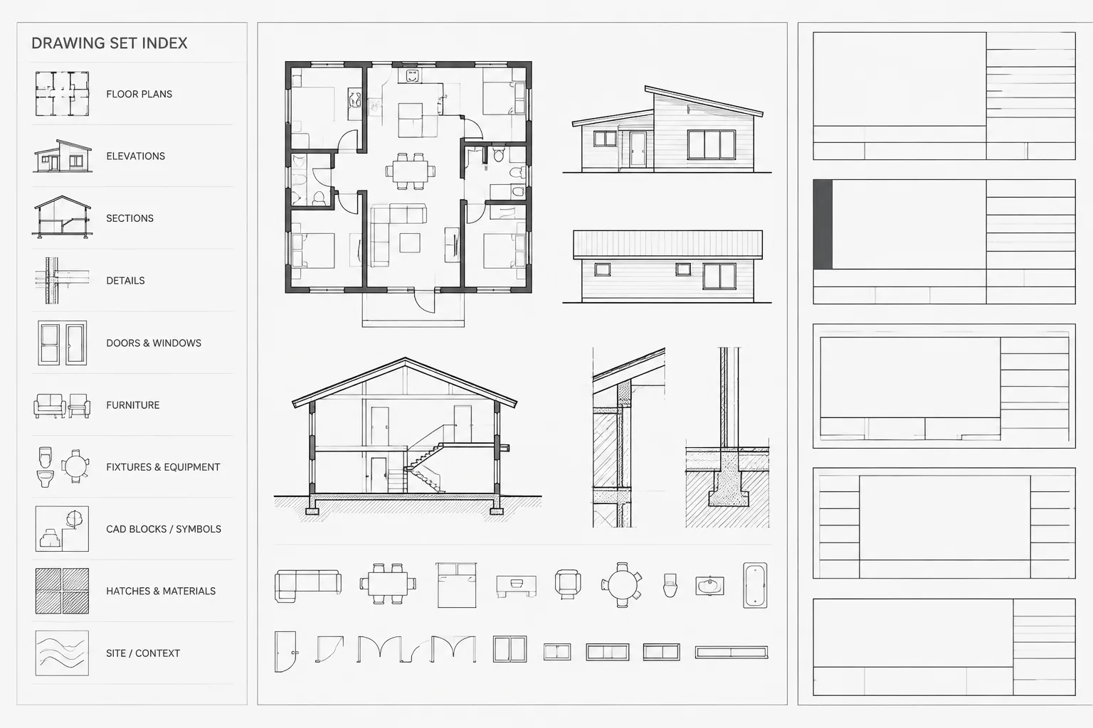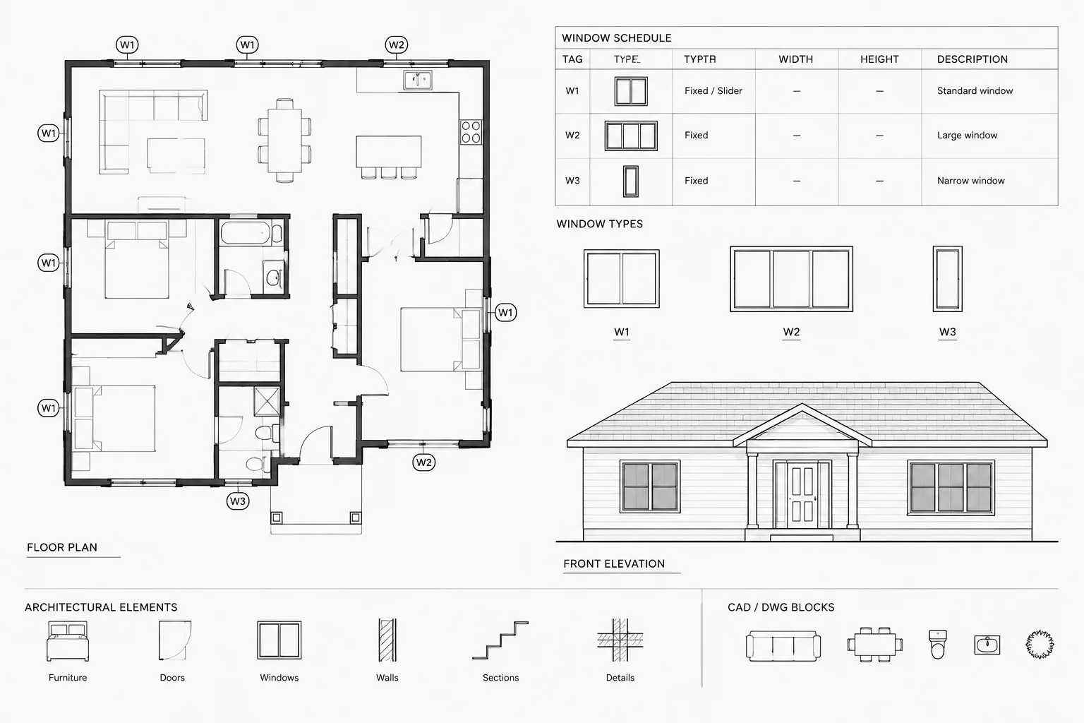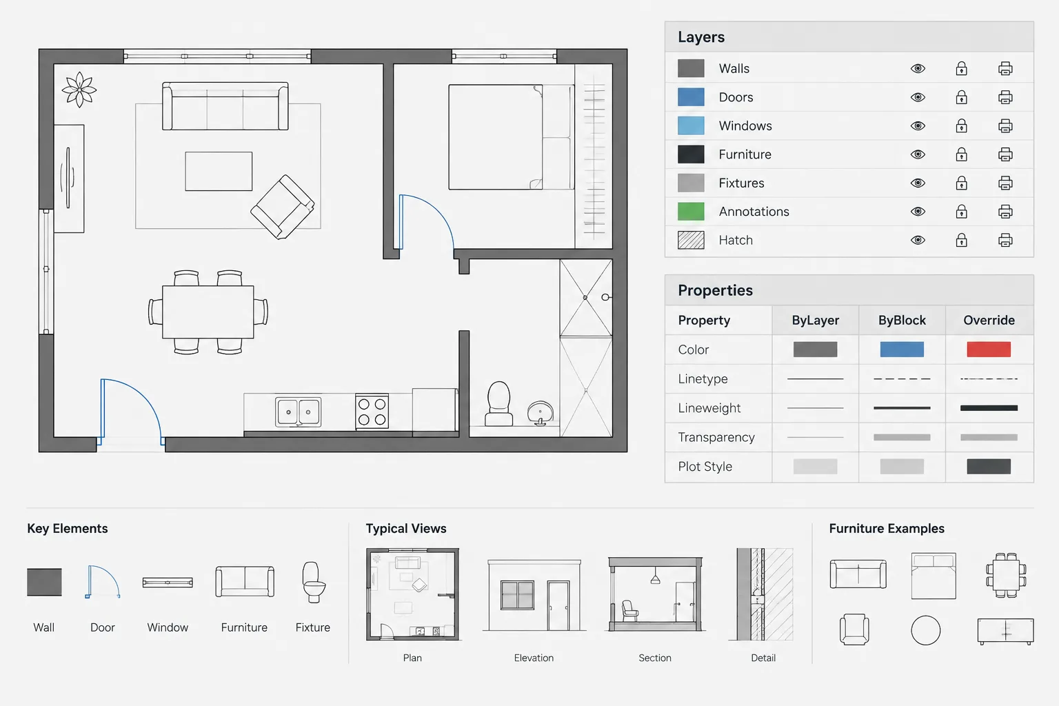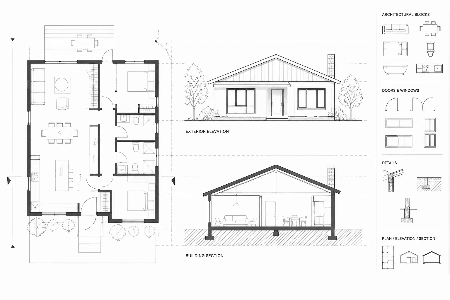
To align architectural plans, elevations, and sections in CAD, treat them as connected descriptions of the same geometry rather than isolated drawings. A dependable workflow transfers horizontal positions from the plan, establishes heights from verified datums, and checks how each element should appear relative to the viewing or cutting direction.
The guidance below explains how to organize reference geometry, project critical locations, distinguish cut elements from objects beyond, and review related views after design changes. It applies to both shared drawing environments and workflows that use separate referenced files.
Architectural plans, elevations, and sections describe the same building from different directions. When these views are drafted independently, small inconsistencies can quickly appear: a window shifts away from its plan opening, a roof edge changes height, or a wall shown in section no longer aligns with the floor plan.
A reliable CAD workflow treats each view as part of one coordinated geometric system. Plans establish horizontal locations, while elevations and sections confirm vertical relationships. Construction lines, reference datums, consistent source geometry, and deliberate checking help maintain that connection without making the drawing difficult to edit.
Why view alignment matters
Misalignment is more than a graphic problem. It can obscure design intent and create uncertainty for anyone reading the drawing set. Common coordination errors include:
- Exterior openings appearing in different locations between plans and elevations.
- Floor, ceiling, parapet, or roof levels changing from one view to another.
- Wall thicknesses or offsets that do not match related sections.
- Columns, stairs, shafts, and major fixtures drifting away from their plan locations.
- Section cuts that omit or incorrectly represent elements crossed by the cutting plane.
- Elevation features that cannot be traced back to identifiable plan geometry.
The goal is not to make every view a direct projection of every line. Architectural drawings use conventions, selective visibility, and graphic simplification. The goal is to make the underlying building geometry consistent while allowing each view to communicate its specific purpose.
Establish a dependable source view
Before projecting geometry, decide which drawing contains the most reliable horizontal information. For many projects, the coordinated floor plan serves as the primary source for wall faces, grids, openings, columns, stairs, and other major elements.
Do not begin an elevation from a rough presentation sketch if a more accurate plan is available. Likewise, avoid projecting from an outdated floor plan copied into another file. Confirm that the source view uses the correct project origin, units, orientation, and current design information.
Identify stable reference geometry
Not every line in a plan is equally useful for alignment. Start with stable references that are unlikely to move independently:
- Structural or planning grids.
- Primary exterior wall faces.
- Major interior wall centerlines or faces.
- Floor and roof extents.
- Column centers or edges.
- Shafts and large openings.
- Stair boundaries and landings.
These references create a framework for coordinating smaller features such as doors, windows, panels, casework, and finish changes.
Use temporary projection geometry
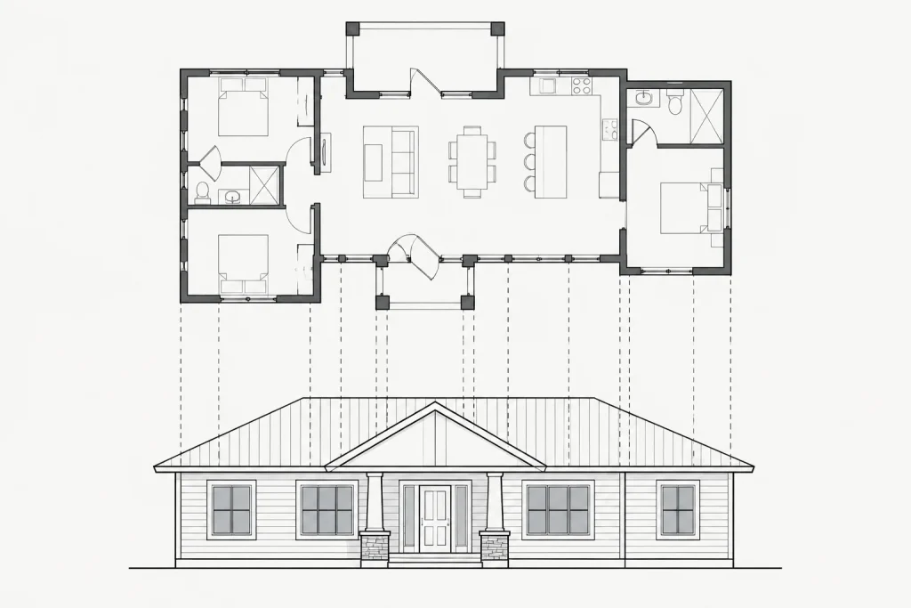
Construction lines are one of the simplest ways to align architectural views in CAD. From the plan, project relevant points toward the elevation or section. These temporary lines can transfer wall corners, opening jambs, column locations, roof edges, and other horizontal positions.
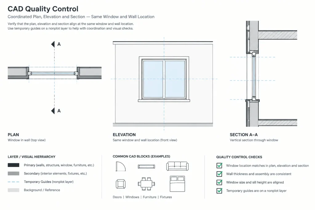
Keep projection geometry separate from finished drawing linework. A dedicated nonplotting layer makes it easier to display, lock, hide, or remove the guides without affecting the plotted view. Use a visually distinct color so construction lines are not mistaken for building elements.
Project only what the view needs
Projecting every plan line creates clutter and makes errors harder to recognize. Instead, transfer geometry in a controlled sequence:
- Begin with the overall building limits and major grids.
- Add primary wall faces and significant offsets.
- Project door and window opening edges.
- Transfer columns, stairs, shafts, and other coordinating elements.
- Add secondary features only after the main geometry is verified.
This hierarchy keeps the working area readable and helps the drafter identify which projected lines control the finished view.
Separate horizontal and vertical control
A plan can establish where an object occurs horizontally, but it generally does not determine its full vertical position. Elevation and section geometry should therefore be built from two coordinated reference systems: projected plan locations and established level datums.
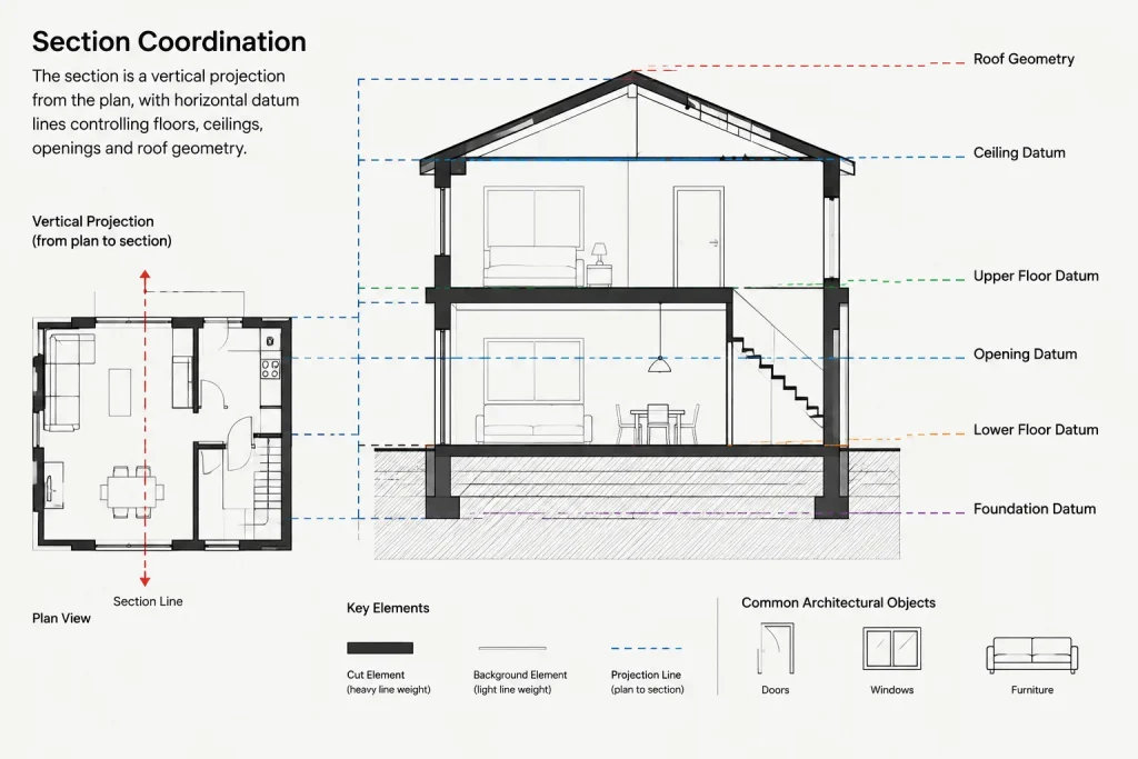
Use horizontal datum lines to control floor levels, landings, ceilings, roof lines, parapets, opening heads, and other height-dependent features. These datums should correspond to the project’s verified level information rather than being estimated from the appearance of another drawing.
| Reference type | Typical information controlled | Primary coordination check |
|---|---|---|
| Plan projection | Wall corners, opening locations, columns, shafts, stair limits | Confirm that horizontal positions match the current plan |
| Level datum | Floors, ceilings, roofs, heads, sills, landings | Confirm that heights match the project level strategy |
| Section cut | Elements intersected by the cutting plane | Confirm what is cut, beyond, overhead, or hidden |
| Grid or centerline | Repeated structural and planning relationships | Confirm consistent identification and spacing across views |
Align an exterior elevation from a floor plan
Start by locating the elevation relative to the plan. Project the exterior building corners and major changes in wall plane. Add the horizontal floor and roof datums, then construct the main elevation outline where those references intersect.
Next, project opening jambs from the plan. Use verified vertical information to establish sills, heads, transoms, and other elevation divisions. Do not assume that a block’s plan width or symbolic representation automatically provides accurate elevation geometry.
Complete larger architectural features before adding surface patterns or decorative detail. Overhangs, canopies, recesses, balconies, screens, and material transitions should connect to recognizable plan geometry whenever possible.
Align a building section from the floor plan
A section requires more interpretation than an elevation because it distinguishes between elements cut by the section plane and objects visible beyond it. Begin by reviewing the section line and viewing direction in the plan. Determine exactly which walls, openings, stairs, floors, roofs, and structural elements the cut crosses.
Project the intersections of the section line with significant plan geometry. Combine those locations with the project’s vertical datums to construct floor assemblies, walls, ceilings, and roof forms. Elements beyond the cut can then be added with an appropriate graphic hierarchy.
Pay special attention to changes in the cutting plane. Jogged sections can communicate useful information, but they may combine elements that are not physically aligned. The section graphics and section marker should make that interpretation understandable.
Maintain a clear line hierarchy
Projection accuracy does not replace good architectural graphics. Once the geometry is coordinated, apply lineweights and linetypes according to what each line represents.
- Use stronger lines or poché for major elements cut in section.
- Use lighter lines for objects seen beyond the cutting plane.
- Differentiate overhead, hidden, or secondary information when it is necessary to understand the view.
- Keep datum and grid graphics readable without allowing them to overpower the building.
- Prevent temporary construction geometry from plotting.
Review the sheet at its intended output scale. A view that looks organized at a close CAD zoom may become dense or ambiguous when plotted.
Choose a coordination method that suits the file structure
Plans, elevations, and sections may be drawn in one model-space file or divided among referenced files. Either method can work if the project team applies it consistently.
When related views share a file, projection lines can connect geometry directly, but the workspace must remain organized. When views are separated, referenced backgrounds can provide controlled source geometry. Avoid casually moving referenced content to make it fit a local drawing. Coordinate origins and insertion settings instead.
Copied geometry should be treated cautiously. Once a plan fragment is copied into an elevation or section file, it can become an outdated snapshot. If copying is necessary, place it on a clearly identified reference layer and replace or verify it after plan revisions.
Check coordination after design changes
Alignment is not a one-time drafting task. Changes to wall positions, opening sizes, floor levels, or roof geometry may affect several views. A practical review should compare the revised area across all related drawings.
Targeted review sequence
- Identify the plan elements affected by the change.
- Locate every elevation and section that shows or cuts through those elements.
- Reproject critical locations instead of relying only on visual comparison.
- Confirm vertical information against the current level datums.
- Update dimensions, tags, notes, detail references, and schedules where applicable.
- Plot or preview the affected sheets to check graphic clarity.
A cloud or revision marker can identify where a sheet changed, but it does not prove that related views are coordinated. The geometry itself must be checked.
Common mistakes to avoid
- Eyeballing alignment: Visual approximation may be acceptable during early sketching but is unreliable for coordinated construction drawings.
- Using dimensions as drawing geometry: A dimension reports a relationship; it should not replace dependable source lines and datums.
- Projecting from outdated files: Confirm the status of a plan or reference before using it as a geometric source.
- Leaving guides mixed with finished linework: Temporary references should remain easy to isolate and should not plot.
- Ignoring the section cut location: A technically aligned section can still be incorrect if it depicts elements the cutting plane does not cross.
- Updating only the obvious view: A plan revision may also affect elevations, sections, enlarged plans, interior elevations, details, and schedules.
A coordinated drawing is easier to trust
Clear architectural documentation depends on agreement between views. Plans provide horizontal control, datums establish vertical control, and elevations and sections explain the resulting form. By projecting stable geometry, separating temporary guides from finished linework, and rechecking related views after revisions, CAD users can reduce contradictions and produce a drawing set that is easier to read, review, and maintain.
A practical cross-view coordination check
After the primary drafting work is complete, review the building by element rather than checking each view in isolation. Select a wall, opening, stair, column, shaft, roof edge, or other significant feature and trace it through every drawing where it should appear.
Check location, height, and representation separately
- Location: Confirm that the feature returns to the same plan reference, wall face, grid, centerline, or opening edge.
- Height: Confirm that its vertical position follows the current floor, ceiling, landing, roof, or opening datum.
- Representation: Confirm that the feature is shown as cut, visible beyond, overhead, hidden, or omitted according to the view.
- Annotation: Check that dimensions, tags, notes, and references describe the coordinated geometry rather than an earlier condition.
This separation is useful because a feature can occupy the correct location while still being shown at the wrong height or with the wrong graphic convention.
Use a change-impact list
When geometry changes, record which related views may be affected before editing. A moved opening may require updates to the plan, exterior elevation, interior elevation, building section, wall detail, dimensions, tags, and schedules. The exact list depends on the drawing set, but identifying affected views first reduces the chance of leaving an outdated representation behind.
Diagnose mismatches from the source outward
If two views disagree, avoid adjusting the cleaner-looking view merely to make the drawings appear aligned. First identify the current source geometry and verified datum information. Then determine whether the mismatch came from an outdated reference, moved local linework, an incorrect section interpretation, or an annotation that no longer follows the geometry.
A final plotted or print-preview review remains important. Temporary guides, dense linework, weak cut emphasis, or overlapping annotations may not be obvious while working closely in CAD, even when the underlying geometry is correct.
Frequently asked questions
Should the floor plan always control the elevation?
The floor plan commonly controls horizontal positions such as wall faces, openings, columns, and offsets. Vertical positions should come from verified level datums and other current project information. If the plan is outdated or incomplete, it should not be treated as the controlling source until it is coordinated.
Why can a projected section still be incorrect?
Projection transfers location, but a section must also interpret the cutting plane. The drafter must determine which elements are cut, which are visible beyond, and which should not appear. Jogged cuts and changes in viewing direction require particular care.
Should construction lines remain in the CAD file?
They may remain when they are useful for future checking, provided they are isolated from finished linework and prevented from plotting. Obsolete or ambiguous guides should be removed so they are not mistaken for current control geometry.
How should separate plan and elevation files be coordinated?
Use consistent origins, orientation, and reference placement. Referenced source geometry is generally easier to verify than an unmanaged copied fragment. If geometry must be copied, identify it clearly and recheck it whenever the source drawing changes.
What is the fastest way to find alignment errors?
Trace major elements across related views using stable plan references and level datums. Openings, wall steps, columns, stairs, shafts, floor edges, and roof transitions often reveal inconsistencies because they depend on both horizontal and vertical control.
Does geometric alignment guarantee a coordinated drawing set?
No. Geometry may align while dimensions, tags, notes, schedules, detail references, or line hierarchy remain outdated. Coordination includes both the building representation and the information used to explain it.