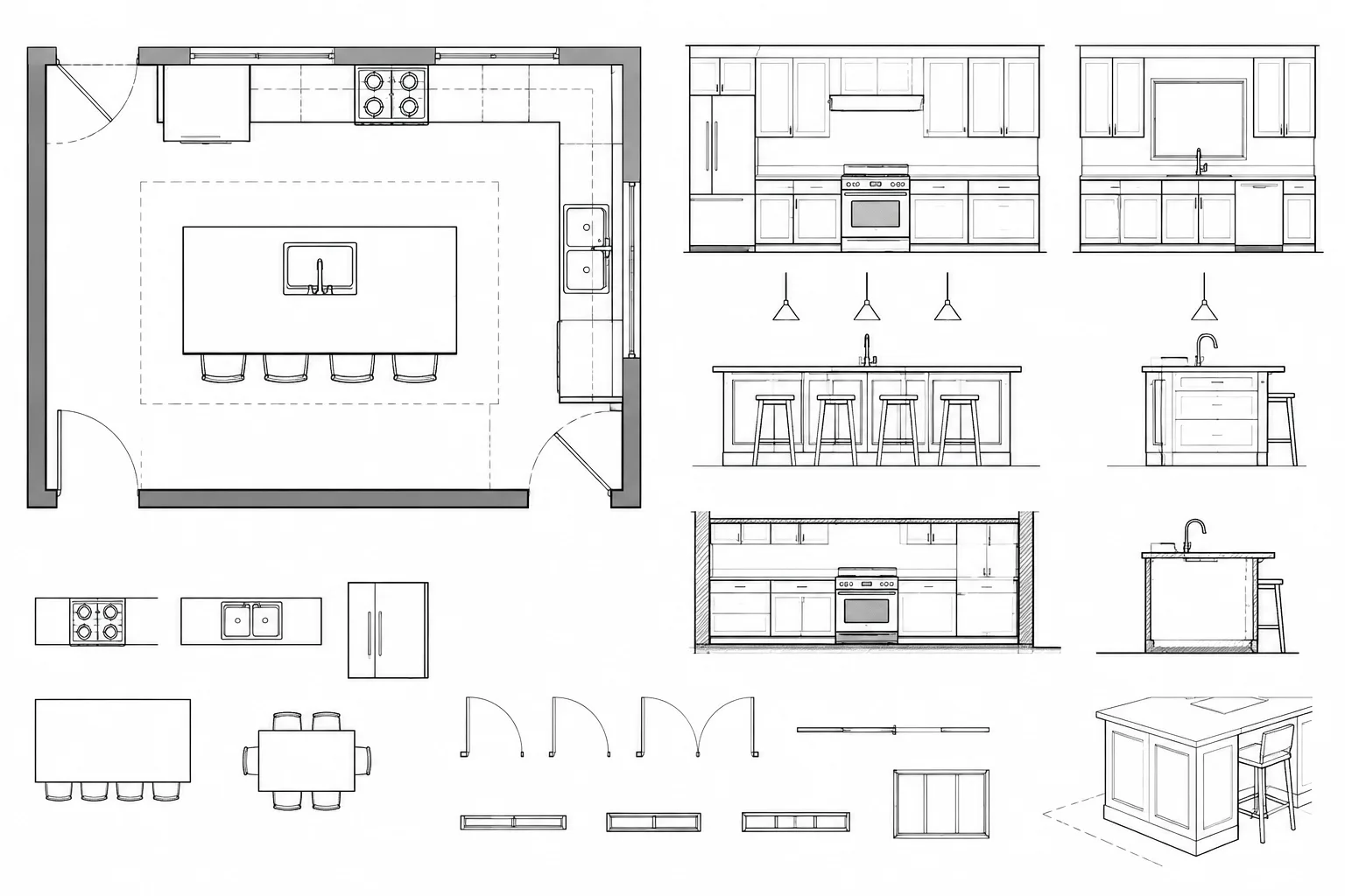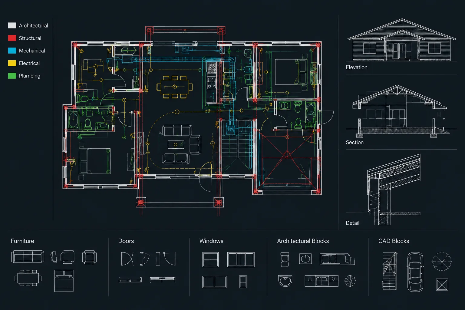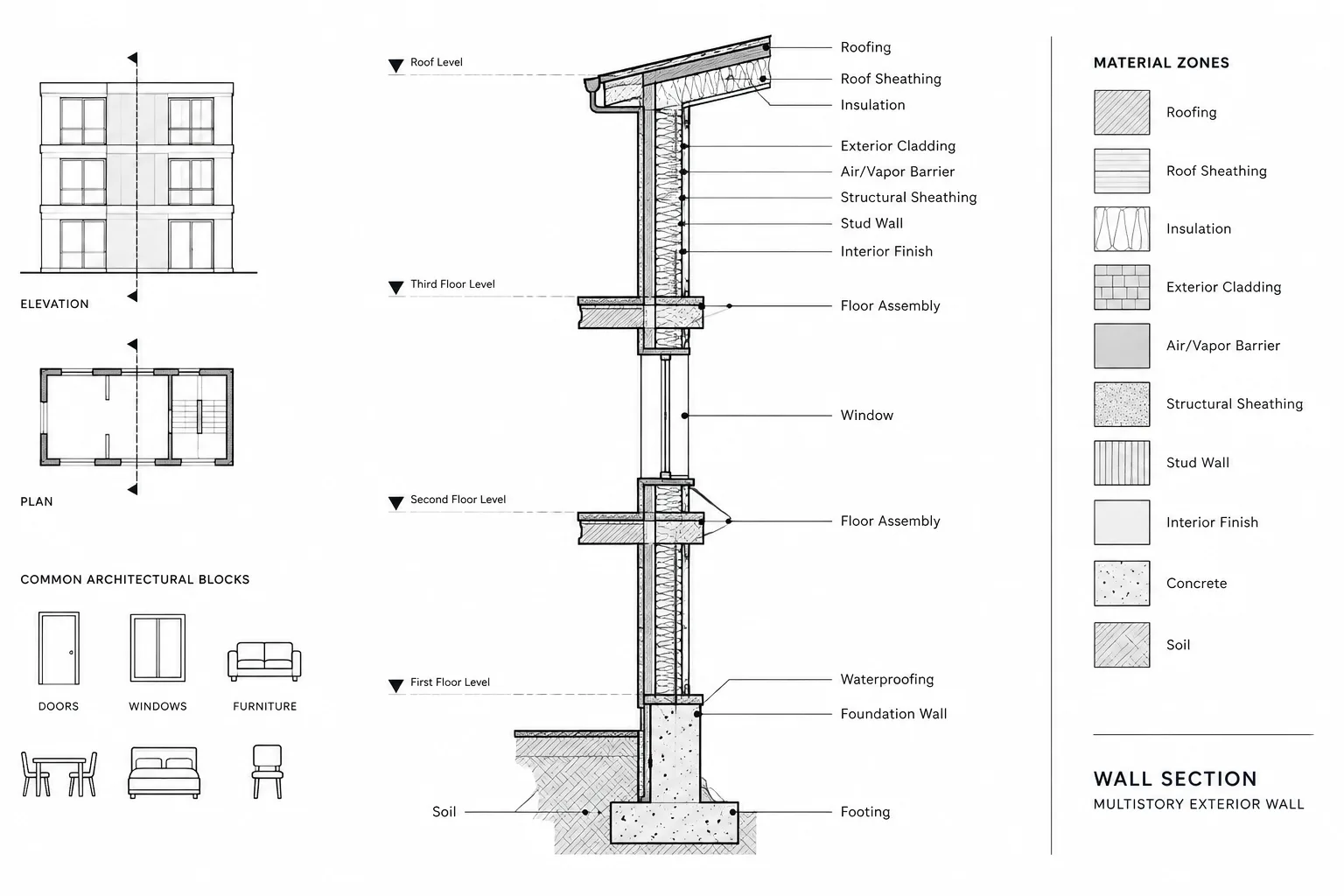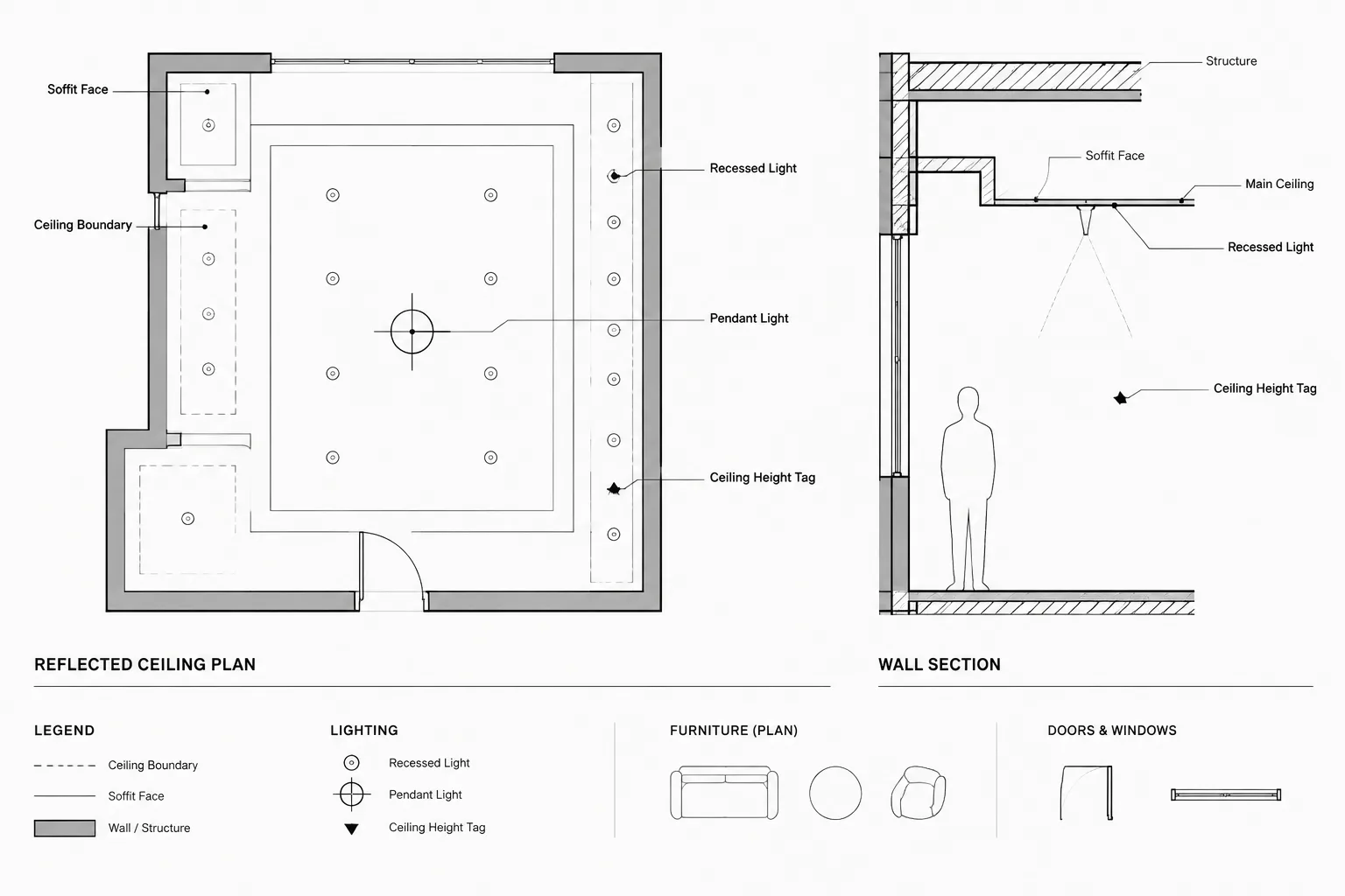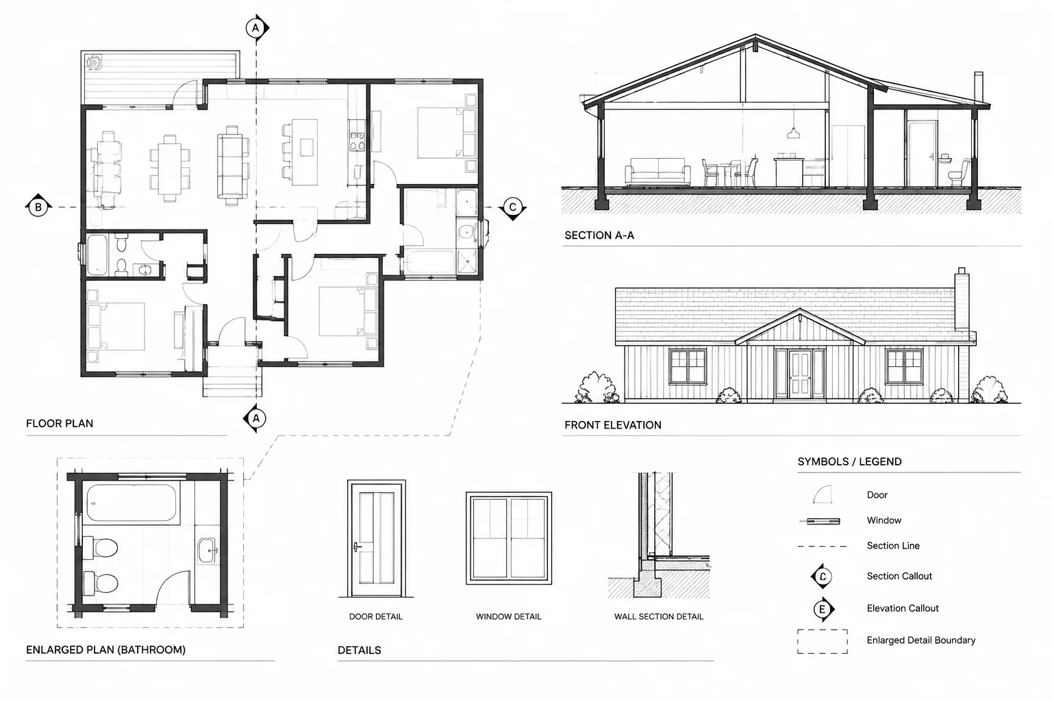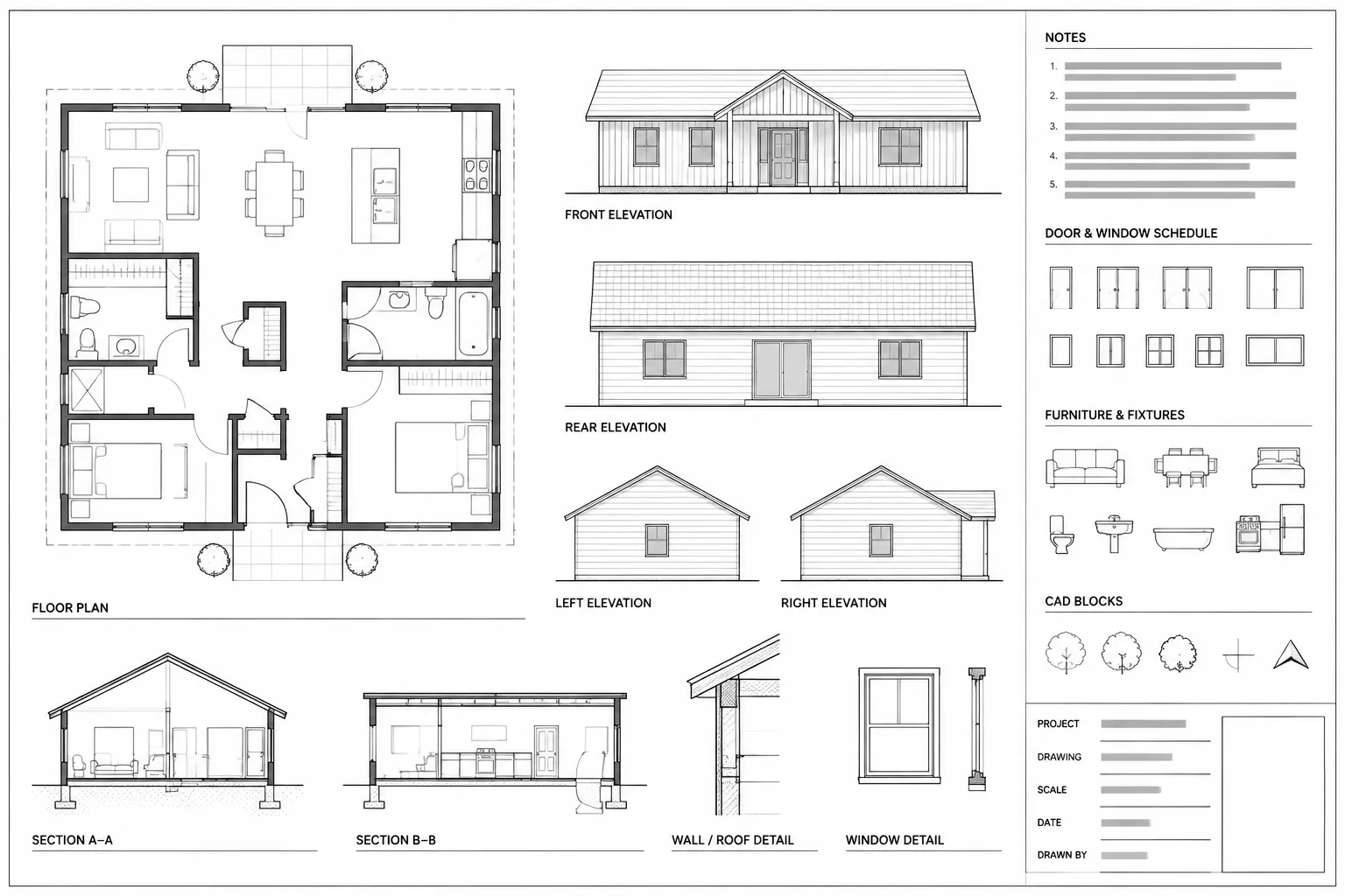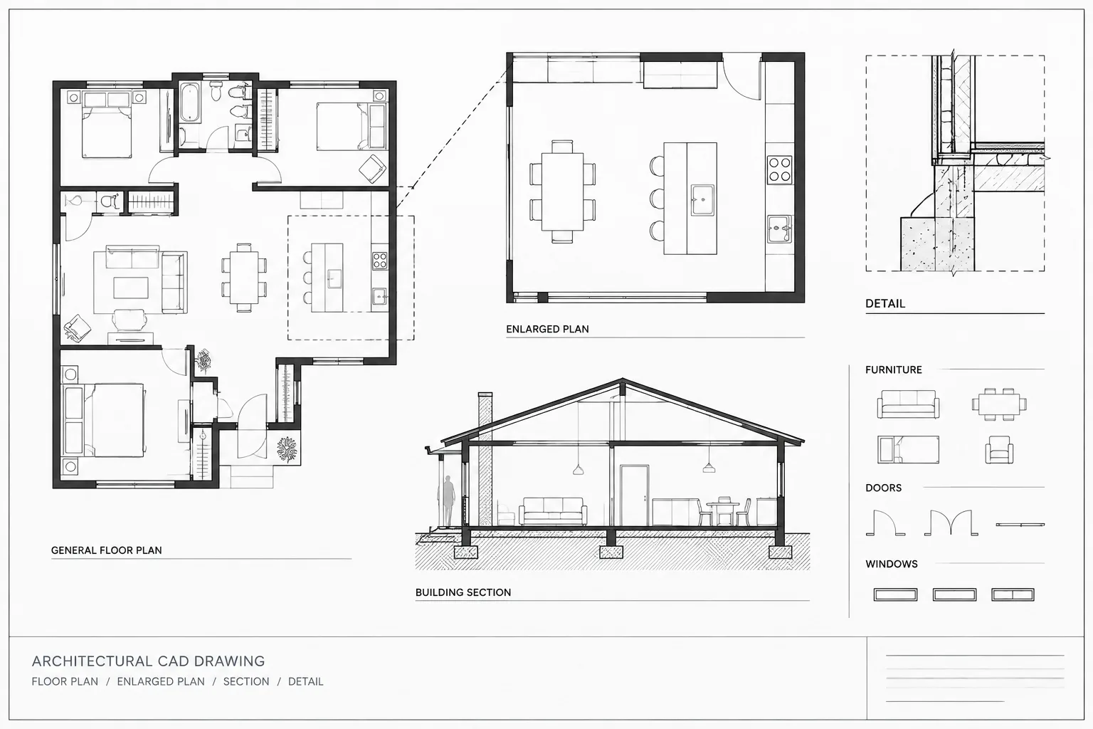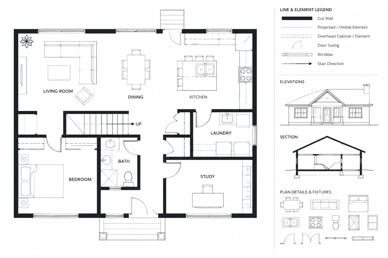
Understanding the cut plane is essential to producing a floor plan that reads as a coordinated architectural drawing rather than an unfiltered top view. Every line should indicate whether an element is intersected, visible in projection, located overhead, concealed, or included for reference.
This guide explains a practical floor plan cut plane CAD drafting workflow. It focuses on graphic hierarchy, layer organization, selective use of overhead linework, coordination with related views, and plot-based quality control. Apply these principles together with the conventions established for the project and office.
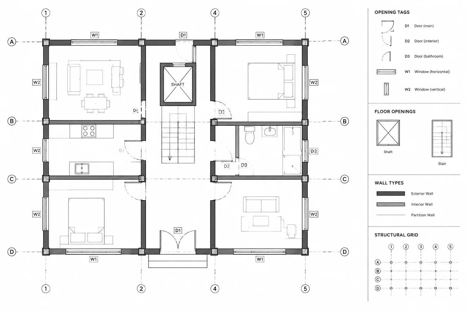
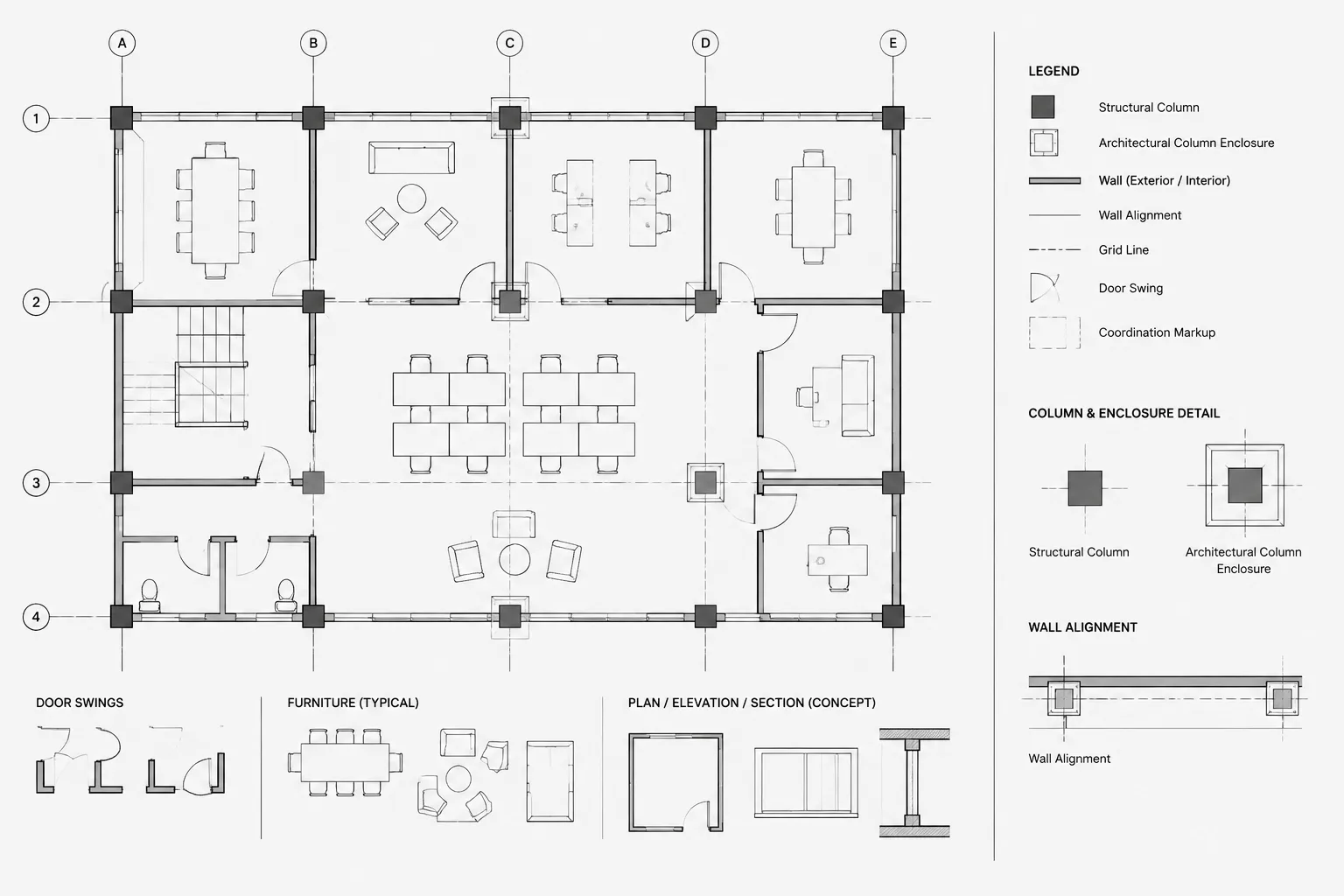
An architectural floor plan is not simply a top view of a building. It is a horizontal section combined with selected information from above and below the viewing plane. Walls, doors, windows, stairs, cabinets, ceiling features, and changes in floor level may all appear differently depending on their relationship to the plan cut plane.
Clear floor plan cut plane CAD drafting requires more than choosing a dashed or continuous linetype. The drafter must decide which elements are cut, which are visible beyond the cut, which belong overhead, and which should be omitted to prevent clutter. These decisions should follow the project’s drawing conventions and remain consistent across plans, enlarged views, elevations, and sections.
What the Floor Plan Cut Plane Represents
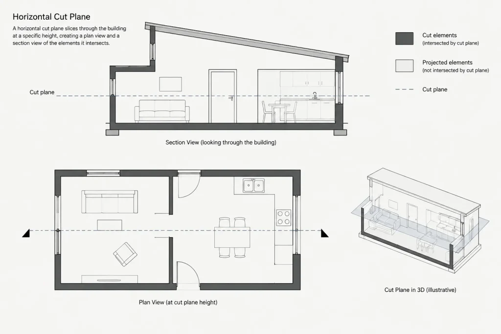
The cut plane is an imaginary horizontal slice through the building. Elements intersected by that slice are represented as cut geometry. Objects visible beyond the slice are shown as projected or viewed geometry. Selected objects above the slice may also be included when they are important to understanding the space.
The exact viewing convention can vary by project, office, building type, and drawing purpose. A general floor plan may emphasize room organization and openings, while an enlarged plan may show cabinetry, fixture relationships, and overhead clearances in greater detail. Do not assume that one universal cut height or graphic convention applies to every drawing set.
A useful way to classify plan information is:
- Cut elements: walls, columns, shafts, and other construction intersected by the horizontal slice.
- Visible elements below or beyond the cut: floors, fixtures, furniture, counters, stairs, and similar objects seen in projection.
- Overhead elements: cabinets, roof overhangs, beams, openings, soffits, or other features above the cut plane that affect coordination.
- Concealed elements: selected construction hidden from ordinary view but required for a particular plan’s purpose.
- Reference information: grids, room tags, dimensions, section markers, elevation callouts, and notes.
Build a Graphic Hierarchy Before Drafting Details
A readable plan should communicate depth and importance even when printed without color. Lineweight, linetype, hatch, and spacing should work together rather than compete.
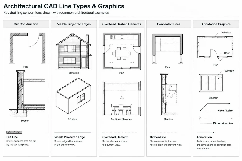
| Plan information | Typical graphic treatment | Drafting purpose |
|---|---|---|
| Cut construction | Prominent continuous outlines, sometimes combined with poche or material hatch | Defines the primary enclosure and structural interruptions |
| Visible projected edges | Lighter continuous lines | Shows objects and surfaces beyond the cut |
| Overhead elements | Distinct dashed or office-standard overhead linetype | Identifies relevant construction above the viewing plane |
| Concealed items | Hidden-line convention appropriate to the drawing type | Shows information not directly visible but necessary for coordination |
| Annotations | Consistent plotted weight with controlled spacing | Explains, locates, and references the geometry |
The strongest lines generally belong to elements physically cut by the plan. Visible furniture, fixtures, and finish edges should not overpower walls or columns. Overhead lines must be recognizable without becoming so dense that they obscure dimensions and room information.
Set Up Layers by Meaning, Not Just Appearance
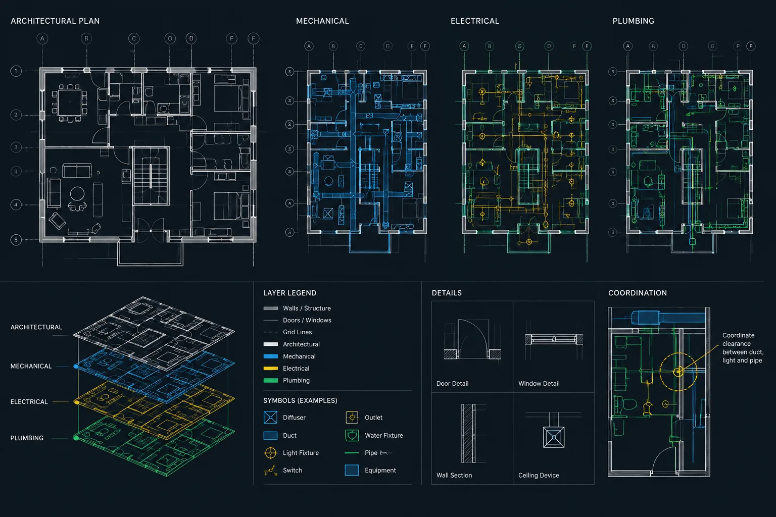
Separating plan graphics by meaning makes the DWG easier to revise, coordinate, and plot. Avoid placing all dashed objects on one generic layer simply because they share a linetype. An overhead cabinet and a concealed structural element may look similar in one view but serve different coordination purposes.
A practical layer strategy can distinguish among:
- Cut walls and other cut architectural construction
- Projected architectural edges
- Overhead architectural elements
- Floor openings and changes in level
- Casework, fixtures, and equipment
- Structural or consultant reference geometry
- Hatches and poche
- Dimensions, tags, notes, and callouts
Use object properties consistently through the layer system unless a controlled exception is necessary. Color should support drafting and layer management, but plotted lineweight and linetype should carry the final graphic meaning. Verify the plotted result rather than judging only from the model-space display.
A Step-by-Step Drafting Workflow
1. Establish the purpose of the plan
Decide what the drawing must communicate before selecting visible geometry. A general arrangement plan, demolition plan, finish plan, and enlarged room plan may use the same base walls but require different overhead and concealed information.
If the drawing has a narrow purpose, omit unrelated geometry. Showing every available edge from a model or reference file often produces a technically dense but visually weak plan.
2. Identify the cut elements
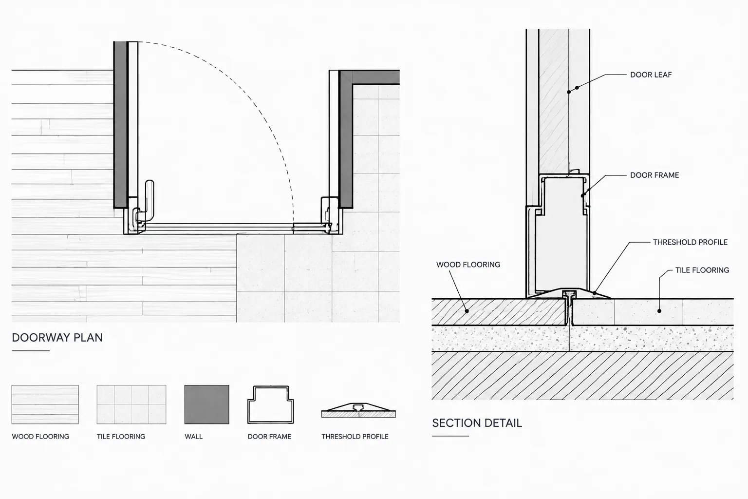
Trace or verify the walls, columns, shafts, stairs, and other construction intersected by the intended cut plane. Check openings carefully. A door or window symbol should coordinate with the wall opening, frame location, adjacent finishes, and related schedule information.
Where geometry changes vertically, consult elevations and sections rather than guessing from the floor plan. Sloped walls, split levels, tall openings, partial-height partitions, and projecting features may require a local graphic decision or explanatory note.
3. Add projected information selectively
Show surfaces and objects visible beyond the cut where they help users understand the plan. Common examples include counters, plumbing fixtures, floor pattern boundaries, stair runs, furniture, and equipment.
Keep projected outlines lighter than cut construction. Simplify blocks when small product details create visual noise at the intended plotting scale. The purpose of a plan symbol is usually to communicate location, orientation, clearance relationships, and identity—not every manufacturing feature.
4. Add overhead elements that affect use or coordination
Overhead graphics are most useful when they explain something that cannot be understood from the visible floor-level geometry alone. Examples may include upper cabinets, soffits, roof overhangs, beams, openings above, folding partitions, or the continuation of a stair.
Use a consistent overhead linetype and keep the geometry on identifiable layers. If several overhead systems overlap, avoid stacking indistinguishable dashed lines. Consider whether a reflected ceiling plan, section, interior elevation, or enlarged detail is the better place for secondary information.
5. Resolve elements crossing the cut plane
Some components cannot be represented adequately by a single graphic treatment. A stair may include cut portions, visible treads, an upward or downward direction indicator, and construction continuing beyond the viewing range. A sloped ceiling or ramp may also cross several vertical zones.
Break such objects into logical graphic segments. Do not rely on one complex block if its linework cannot respond clearly to the intended view. Use plan breaks, direction symbols, notes, and references to sections where needed, following the project’s established conventions.
6. Coordinate annotations after the geometry is stable
Place dimensions, room tags, door tags, wall tags, section markers, and notes after the major cut and overhead conditions have been resolved. Annotation should not conceal critical intersections or make an overhead line appear continuous when it is not.
Where possible, create clear annotation zones. Keep dimension strings outside dense geometry, maintain readable gaps around text, and check that leaders terminate at unmistakable locations.
Common Floor Plan Graphic Problems
Using hidden lines for every overhead object
Not everything above the cut plane belongs on the plan. Excessive overhead information can make cabinets, beams, ceiling features, and consultant systems visually merge. Include only information that serves the plan’s purpose.
Giving furniture the same weight as walls
Downloaded furniture blocks often contain heavy outlines, dense curves, or nested details. Standardize their layers and properties before use. Furniture should support spatial understanding without competing with cut construction.
Leaving unexplained breaks in walls or floors
An opening that appears obvious to the drafter may be ambiguous to a contractor or reviewer. Coordinate plan openings with sections, elevations, tags, and notes. Verify whether the edge is cut, projected, overhead, or simply missing.
Depending on screen color instead of plotting
A plan can look organized on a dark CAD background but lose its hierarchy when printed. Dashed lines may appear continuous, poche may become too strong, and light projected edges may disappear. Review test plots or plot previews at the intended sheet scale.
Copying inconsistent graphics from reference files
External references and consultant backgrounds may use different layer names, linetypes, and lineweight assumptions. Control their appearance without destroying the source information. Confirm which discipline owns each element before redrawing or suppressing it.
Coordinate the Plan with Sections and Elevations
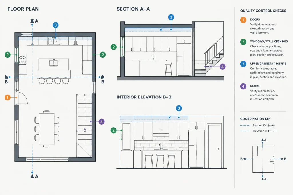
Sections and elevations are essential checks for plan cut logic. If an overhead cabinet appears in plan, its extent should agree with the relevant interior elevation. If a wall changes height, that transition should be evident in another view. If a stair is cut in plan, its direction and continuation should correspond to the section and adjacent floor plan.
Use a focused coordination review:
- Compare wall and opening locations across plans, sections, and elevations.
- Check that overhead features stop and start at the correct boundaries.
- Confirm that vertical transitions have a section, elevation, or note where needed.
- Verify that floor openings and shafts align between levels.
- Review referenced files for changes that alter cut or projected conditions.
- Confirm that tags and callouts point to the correct drawing views.
Final Plot Review Checklist
- Cut construction reads first and forms a clear enclosure.
- Projected objects remain visible without overpowering the plan.
- Overhead and concealed lines have distinct, consistent meanings.
- Linetype patterns remain legible at the plotted scale.
- Hatches and poche do not hide openings, fixtures, or annotations.
- Furniture and equipment blocks use appropriate detail and lineweight.
- Annotations do not collide with dashed or cut geometry.
- Plan conditions agree with related sections, elevations, and enlarged views.
- Unnecessary reference geometry is hidden or screened appropriately.
- The sheet remains understandable when viewed or printed without color.
Make the Cut Plane a Deliberate Drawing Decision
Effective floor plan drafting depends on selecting and organizing information, not merely displaying all available geometry. Classifying elements as cut, projected, overhead, concealed, or annotative provides a reliable basis for layer organization and lineweight control.
When unusual conditions arise, use sections and elevations to verify the geometry and follow the project’s documented drafting conventions. A carefully edited plan communicates spatial relationships quickly, coordinates more reliably with other views, and remains readable throughout design and construction documentation.
A Practical Test for Ambiguous Plan Geometry
When the correct representation of an element is unclear, evaluate it by location, visibility, and drawing purpose. First determine whether the horizontal slice physically intersects the object. If it does, the intersected portion normally belongs to the cut hierarchy. If it does not, decide whether the object would be visible beyond the slice, located overhead, or concealed by other construction.
Next ask whether showing the element improves the intended use of the plan. Geometry may be accurate but still unnecessary. An overhead feature that affects circulation, cabinetry coordination, or spatial interpretation can be useful, while unrelated detail may be better reserved for another view.
Finally, compare the condition with sections, elevations, enlarged plans, and referenced backgrounds. This review helps distinguish a legitimate graphic exception from an unresolved modeling or drafting error.
Separate Classification from Graphic Styling
Classify an object before deciding how it should look. Assigning a dashed linetype first can blur the difference between overhead construction, concealed work, and geometry imported from another discipline. Those categories may require different layer control, visibility settings, and annotation even when their on-screen appearance is temporarily similar.
A dependable sequence is to identify what the object represents, determine why it belongs in the view, place it in the appropriate drawing category, and then apply the project’s graphic convention. This makes later revisions easier because visibility and plotting can be controlled by meaning rather than by isolated property overrides.
Review the Plan as a Communication Document
Before issue, read the plan without relying on model knowledge or screen color. Trace the enclosure, locate openings, follow circulation, identify vertical connections, and check the extents of overhead features. If a condition cannot be understood from the plotted hierarchy and its references, revise the linework, annotation, or supporting view rather than expecting the reader to infer the intent.
Frequently Asked Questions
What is the difference between an overhead line and a hidden line?
An overhead line identifies selected geometry above the plan cut that is intentionally shown to explain the space. A hidden line generally represents relevant geometry concealed from ordinary view. The exact graphic treatment should follow the project’s documented conventions, but the categories should remain distinct in the layer structure.
Should every object above the cut plane appear dashed?
No. Include overhead objects only when they contribute to the purpose of the plan. Showing every upper cabinet, beam, soffit, ceiling feature, or consultant element can obscure more important information and weaken the drawing hierarchy.
How should a stair be represented when it crosses the cut plane?
Separate the stair into logical graphic portions representing cut, visible, and continuing geometry. Direction symbols, plan breaks, notes, and references to related sections can clarify movement and continuation. Use the project convention consistently across connected floor plans.
Why do overhead lines look clear in CAD but unclear on the sheet?
Display color and zoom level can make closely spaced or light linework appear more distinct than it will when plotted. Plot scale, linetype behavior, screening, lineweight, and nearby annotations all affect readability. Review a plot preview or test output rather than relying only on model-space appearance.
Should imported blocks keep their original layers and lineweights?
Not automatically. Review imported furniture, fixtures, equipment, and casework before placing them in the drawing. Simplify unnecessary detail and map their properties to the project’s layer and plotting system while preserving the information needed for coordination.
When should information move to another drawing view?
Move information when it cannot be shown clearly without crowding the floor plan or confusing the graphic hierarchy. A reflected ceiling plan, section, elevation, enlarged plan, or detail may communicate overhead and vertical relationships more effectively.