Door hardware coordination in architectural CAD is primarily an information-management task. The plan, door schedule, hardware set, details, and consultant drawings may each describe a different part of the same opening. Coordination succeeds when those documents use a stable opening identifier and communicate compatible design intent.
This guide explains how to connect door geometry with scheduled data without overloading the floor plan. It also outlines practical checks for tags, swings, special devices, electrified openings, enlarged views, CAD layers, and drawing revisions. Project-specific code, accessibility, security, fire-protection, and product requirements must still be confirmed by the responsible professionals.
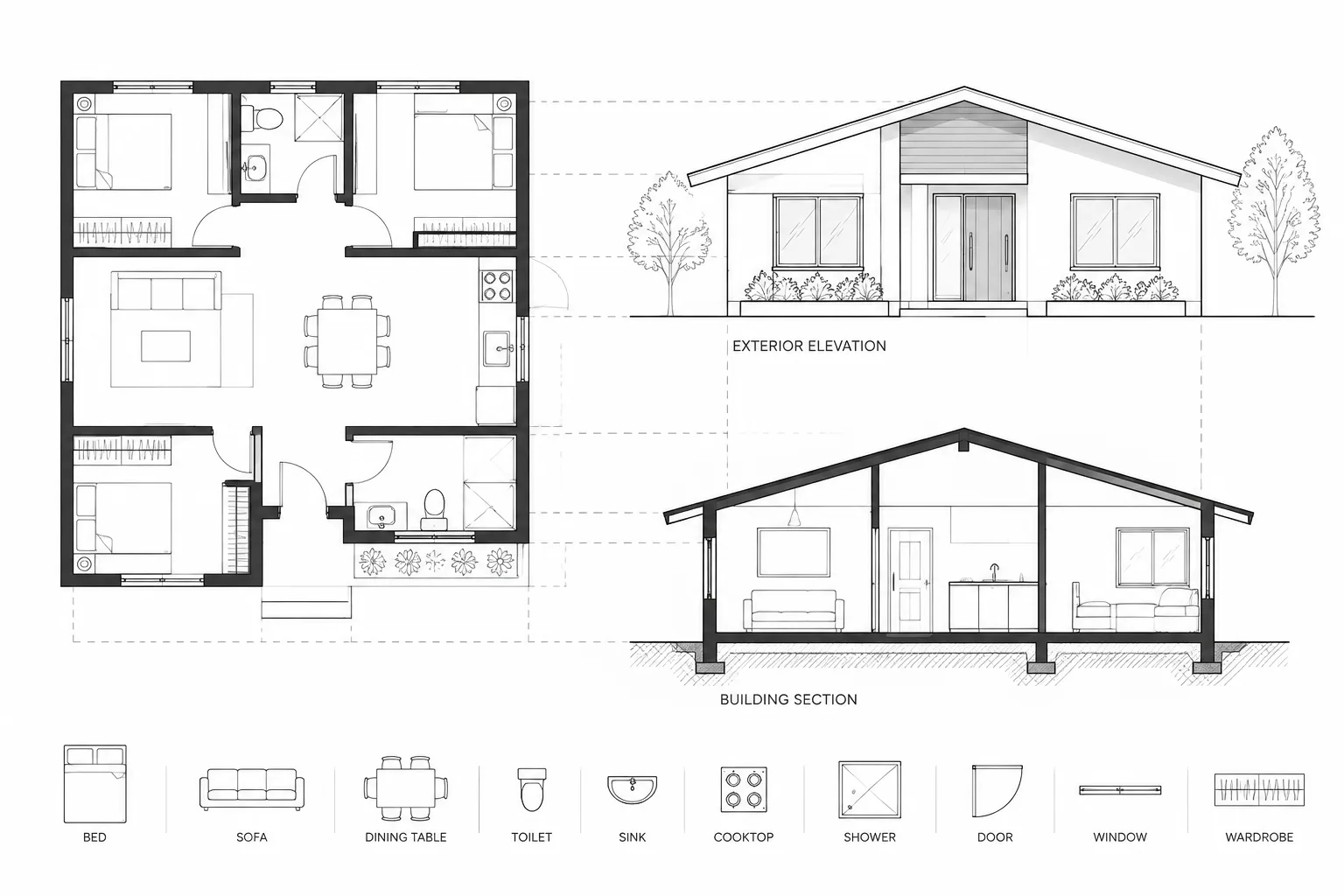
Door hardware is rarely communicated by a single drawing. The floor plan shows the opening and swing, the door schedule identifies the leaf and frame, hardware information defines the operating components, and details explain physical interfaces. Electrified openings may also connect to access control, fire alarm, security, and electrical documents.
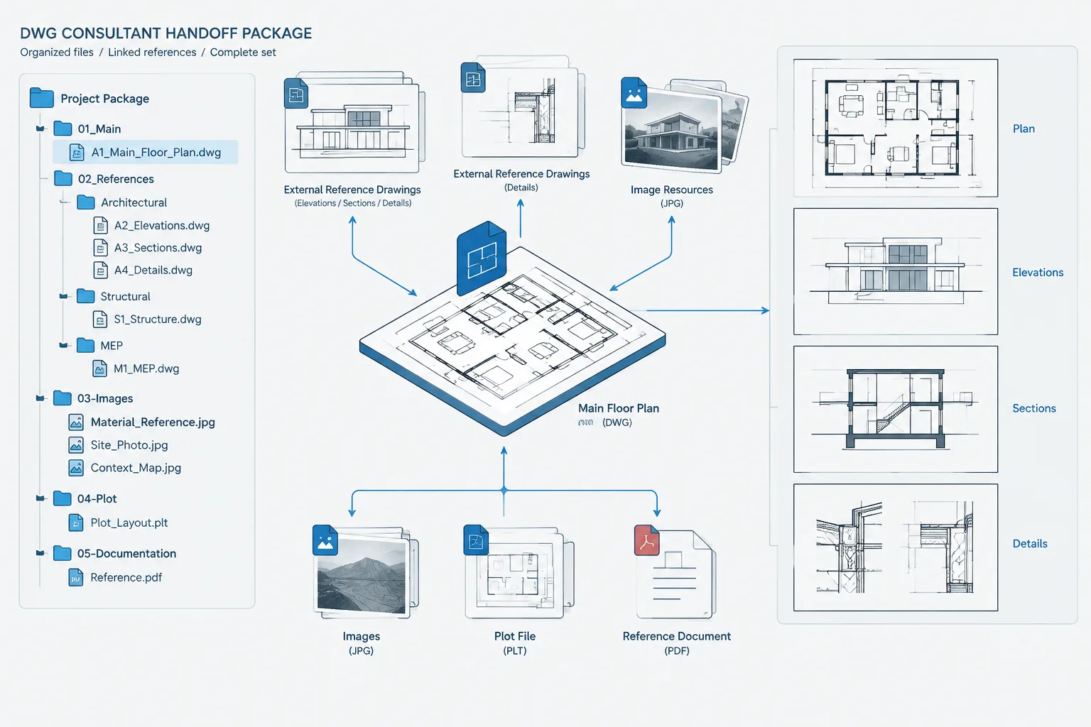
A reliable door hardware coordination workflow does not attempt to draw every hinge, closer, lock, or sensor in plan. Instead, it establishes clear identifiers and keeps the graphical and data-based information synchronized. The goal is to make each opening traceable from plan to schedule, hardware set, elevation, detail, and consultant document.
Separate Door Geometry from Hardware Information
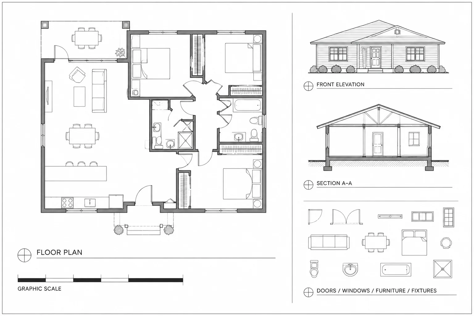
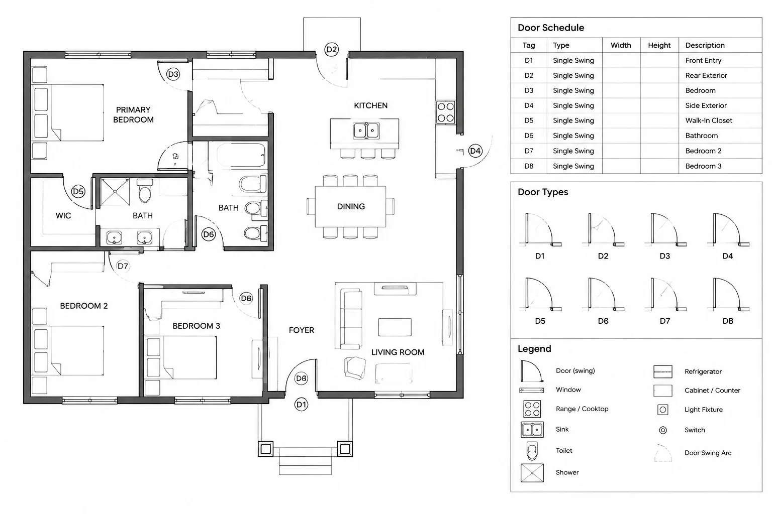
Door geometry and door hardware data serve different purposes. Plan geometry communicates the location, width, leaf arrangement, swing, and relationship to walls or nearby construction. Hardware data describes how the opening operates and what components are associated with it.
Keeping these roles separate prevents crowded plans and reduces duplicated information. A typical architectural plan may show:
- The wall opening and frame location
- The door leaf or leaves
- The swing direction
- The door number or opening identifier
- Special symbols only when they are needed for coordination
The door schedule, hardware schedule, or hardware consultant’s documents can then carry the detailed component descriptions. Do not insert product-specific hardware into a general plan unless the product geometry is necessary to resolve a clearance, mounting, or construction condition.
Build a Clear Information Chain
Every scheduled opening should have a consistent path through the drawing set. A reviewer should be able to start with a plan tag and find the related schedule row, hardware designation, and relevant details without guessing.
| Drawing information | Primary purpose | Coordination question |
|---|---|---|
| Floor plan | Opening location, leaf arrangement, and swing | Is the correct opening shown in the correct wall? |
| Door tag | Links the opening to project data | Is the identifier unique and readable? |
| Door schedule | Summarizes leaf, frame, type, and related data | Does the row agree with the plan condition? |
| Hardware set reference | Connects the opening to hardware requirements | Does the set match the intended operation? |
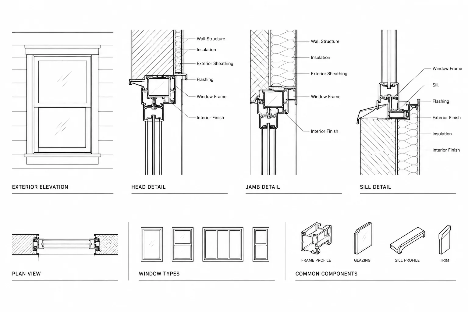
| Elevation or detail | Explains mounting and construction interfaces | Are special components physically coordinated? |
| Consultant documents | Defines specialized security or electrical scope | Are devices and interfaces represented consistently? |
The exact division of information depends on the project team. Before drafting, establish who controls door numbering, hardware set assignments, electrified hardware, access-control devices, and specification language.
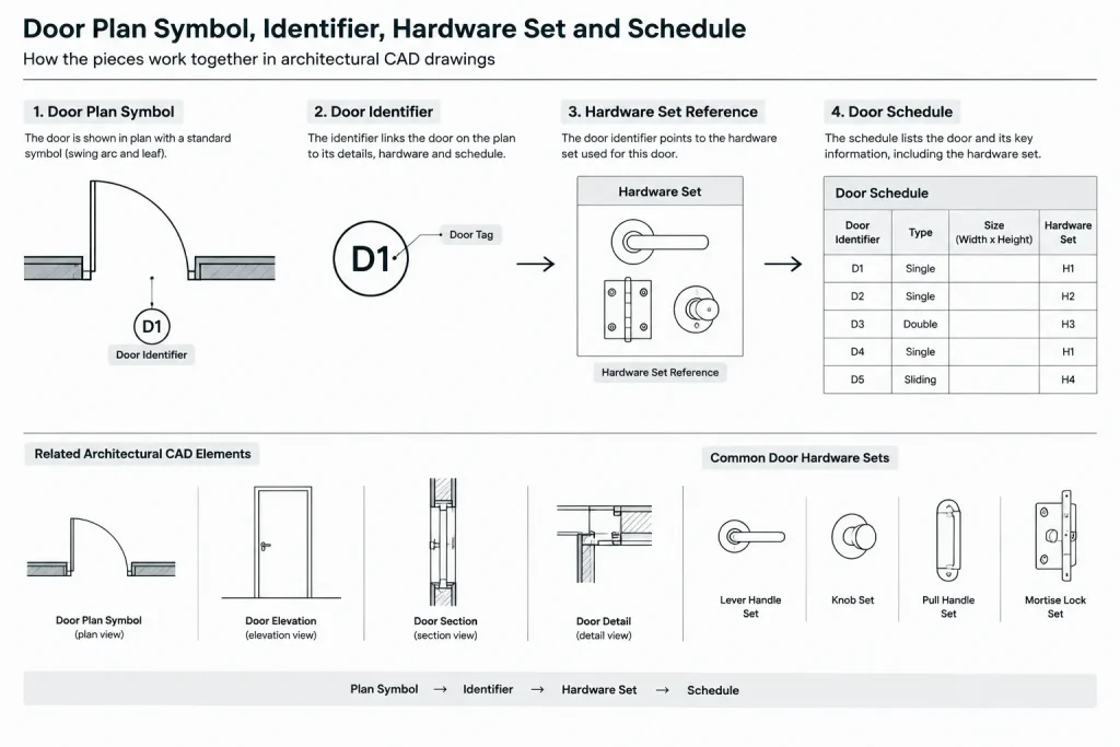
Start with Verified Door Geometry
Hardware coordination is unreliable when the underlying door block is wrong. Confirm the opening geometry before assigning hardware information.
Check the leaf configuration
Verify whether the opening has a single leaf, a pair, unequal leaves, or another arrangement. For paired doors, identify whether the project distinguishes an active leaf from an inactive leaf. Do not infer this solely from a generic block graphic.
Check the swing
The plan swing should agree with the intended operation and the door schedule. Mirroring a door block can change handing or active-leaf logic even when the block still looks visually acceptable. Review copied and mirrored doors carefully.
Check adjacent conditions
Look for nearby walls, casework, plumbing fixtures, equipment, controls, and other doors. Hardware components such as closers, stops, panic devices, pulls, and access-control devices may need more coordination than the simplified plan symbol suggests.
Any required clearances, accessibility provisions, egress conditions, fire-protection criteria, or hardware mounting rules must be verified against the applicable project requirements and current governing documents.
Use Door Tags as Stable Coordination Keys
A door tag should act as a stable database key, not merely as a visible label. If the project uses attributed blocks, keep the door identifier in a dedicated attribute rather than typing unrelated text beside the symbol. This makes auditing and schedule coordination easier.
Good tagging practice includes:
- Using one identifier consistently across plans, schedules, elevations, and details
- Avoiding duplicate identifiers unless the project has a documented naming convention
- Keeping tags legible and clear of swing arcs, dimensions, and wall poche
- Using a separate indicator for hardware sets rather than combining too much data into one tag
- Updating references when an opening is added, removed, or renumbered
If both door numbers and hardware set references appear on plan, give them different graphic roles. For example, the opening identifier may be the primary tag while the hardware set is shown as a smaller secondary reference. The distinction should be explained in the project legend.
Represent Special Hardware Selectively
Most hardware belongs in schedules or specifications, but certain devices affect architectural coordination directly. These may include automatic operators, card readers, request-to-exit devices, magnetic hold-open devices, door position contacts, overhead stops, floor stops, and wall-mounted controls.
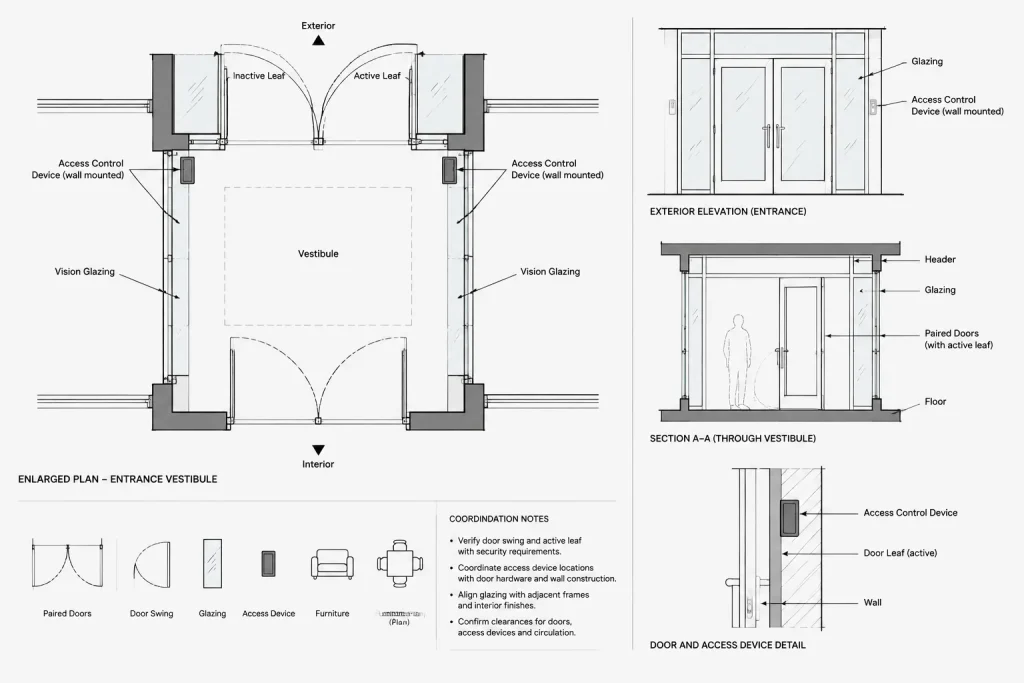
Use symbols only when they help locate or coordinate a real component. Each symbol should have:
- A defined meaning in the legend
- A logical insertion point
- A consistent orientation rule
- A dedicated layer or controlled layer group
- A clear relationship to the associated door
A symbol library should distinguish between schematic devices and objects drawn to represent physical extents. A schematic card-reader symbol, for example, should not be mistaken for verified product dimensions or an exact mounting template.
Coordinate Electrified Openings Across Disciplines
Electrified door hardware creates interfaces between architectural, electrical, security, and life-safety information. The architectural drawing should clearly identify the opening and intended function without duplicating unverified consultant design.
For each electrified opening, review:
- Which document defines the hardware function
- Whether power or pathways are required
- Whether security devices appear on the correct side of the opening
- Whether wall-mounted controls conflict with casework, glazing, or finishes
- Whether the frame or leaf requires preparation for devices or wiring
- Whether consultant device labels reference the same door identifier
Use an agreed responsibility matrix or coordination note to identify scope ownership. Avoid vague labels such as “electrified door” when the team needs to distinguish multiple device functions.
Create Enlarged Views for Congested Openings
A small-scale floor plan may not adequately explain a complex entrance, paired opening, security vestibule, or door adjacent to built-in elements. Create an enlarged plan, elevation, or jamb detail when the condition cannot be communicated clearly at the primary plan scale.
An enlarged coordination view can show:
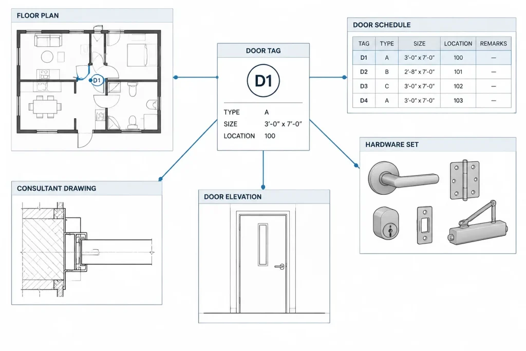
- Door and frame orientation
- Active and inactive leaves
- Wall-mounted device locations
- Nearby switches, controls, or access panels
- Casework and equipment conflicts
- Relevant detail and elevation references
Do not allow the enlarged view to become an independent version of the design. Derive it from the same coordinated background or referenced geometry used by the overall plan whenever the project workflow permits.
Manage Layers and Blocks for Efficient Review
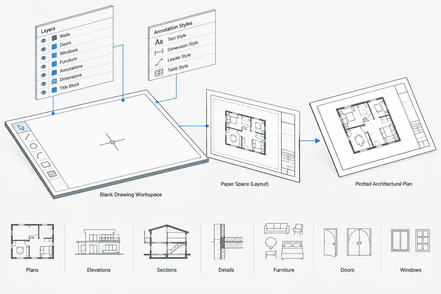
Organize door hardware graphics according to function. Door leaves and frames may belong with architectural opening geometry, while hardware coordination symbols can be placed on separate layers for visibility control. Tags and notes should remain distinct from physical geometry.
Blocks for hardware-related symbols should be simple and predictable. Use a consistent insertion point, avoid unnecessary nested content, and keep object properties controlled through the intended layer or block behavior. Include attributes only when they support a real workflow, such as a device identifier or related door number.
Before sharing files, confirm that custom linetypes, text styles, and symbol definitions display correctly in the issued DWG and plotted sheets.
Run a Door-by-Door Coordination Review
A focused review is more reliable than checking plans, schedules, and hardware documents separately. Move through the project by door identifier and compare all related information.
- Locate the door on plan.
- Confirm the opening, leaf arrangement, and swing.
- Find the corresponding door schedule row.
- Verify the hardware set reference.
- Check elevations and details for special conditions.
- Review security, electrical, and other consultant references.
- Record unresolved conflicts instead of making unsupported assumptions.
Pay particular attention to recently added, deleted, mirrored, or relocated openings. Also review paired doors, exterior entrances, controlled-access doors, doors in glazed systems, and openings adjacent to fixed construction.
Final CAD Quality-Control Checklist
- Every door tag points to a valid schedule entry.
- No unintended duplicate door identifiers remain.
- Plan swings agree with the scheduled opening configuration.
- Hardware set references use the current project designations.
- Special device symbols are defined in the legend.
- Electrified openings are coordinated with relevant consultants.
- Enlarged views agree with the overall plan.
- Deleted doors have been removed from schedules and related notes.
- Tags, symbols, and leaders plot legibly at the intended sheet scale.
- Code, accessibility, fire-rating, security, and product requirements have been verified by the responsible project professionals.
Effective door hardware coordination depends less on drawing every component and more on maintaining a dependable information chain. Stable door identifiers, verified geometry, selective symbols, and a disciplined door-by-door review allow the CAD drawings to support schedules and consultant information without becoming cluttered or contradictory.
Make Change Control Part of the Workflow
Door coordination should continue whenever an opening is added, relocated, mirrored, renumbered, or removed. A change that appears minor on the floor plan can affect the door schedule, hardware assignment, frame preparation, elevations, details, security devices, and consultant references.
When revising an opening, treat the door identifier as the connection between related records. Review every location where that identifier appears rather than assuming that schedule or consultant information will update automatically.
Document unresolved coordination items
Do not resolve missing hardware information by guessing from a nearby door or copying an apparently similar hardware set. Record the question, identify the affected opening, and assign it to the discipline or team member responsible for the decision. This creates a traceable coordination process and helps prevent assumptions from becoming issued information.
Distinguish design intent from product geometry
A schematic CAD symbol can indicate the presence and general location of a device, but it does not establish a manufacturer-specific footprint, mounting template, wiring requirement, or installation clearance. Use verified product information and coordinated details when physical interfaces must be resolved.
Preserve review evidence
Useful coordination records can include marked-up plans, issue logs, schedule comparisons, and consultant comment responses. The purpose is not to create another independent source of door data. It is to show which openings were reviewed, what conflicts remain, and which document controls each decision.
Common Coordination Failures to Watch For
- Orphaned schedule entries: A scheduled door no longer appears on the plan.
- Unscheduled openings: A plan tag has no corresponding schedule record.
- Copied hardware references: A duplicated door retains a hardware assignment that does not match its new function.
- Mirrored graphics: The leaf appears correct graphically, but the handing, active-leaf logic, or device side was not reviewed.
- Conflicting identifiers: Architectural and consultant documents use different labels for the same opening.
- Overdrawn plans: Detailed hardware graphics obscure the opening, dimensions, or nearby construction.
- Uncoordinated removals: A deleted opening remains in notes, elevations, details, or consultant documents.
A disciplined review should prioritize traceability over graphic complexity. If a reviewer can move confidently from the plan tag to the related schedule, hardware information, detail, and consultant reference, the drawing set is easier to check and maintain.
Door Hardware Coordination FAQ
Should every hardware component be drawn on the floor plan?
No. The floor plan should remain readable and should generally show opening geometry, swing, identification, and only the special devices needed for location or interface coordination. Detailed component information belongs in the appropriate schedule, hardware documentation, specification, elevation, or detail.
What is the difference between a door number and a hardware set reference?
The door number identifies a specific opening and connects it to project records. A hardware set reference points to the operating components assigned to that opening. They serve different purposes and should remain graphically distinguishable when both appear on a drawing.
Why are mirrored door blocks a coordination risk?
Mirroring can alter swing, handing, active-leaf relationships, and the side on which coordinated devices appear. A mirrored block may look plausible while retaining attributes or references from the original condition, so both geometry and associated data require review.
When should an enlarged door view be created?
Use an enlarged plan, elevation, or detail when the main floor plan cannot clearly communicate device locations, leaf relationships, adjacent construction, or consultant interfaces. The enlarged view should remain coordinated with the same underlying design information as the overall plan.
How should electrified door hardware appear in architectural CAD?
The architectural drawings should identify the opening and communicate the coordinated design intent without duplicating unsupported consultant information. Device symbols, labels, scope ownership, frame or leaf interfaces, and references should agree across the architectural, electrical, security, and other relevant documents.
Can a CAD hardware symbol be used as an installation template?
Not unless it was created from verified product information specifically for that purpose. Many hardware and security symbols are schematic coordination graphics rather than exact representations of physical size, mounting, or preparation requirements.