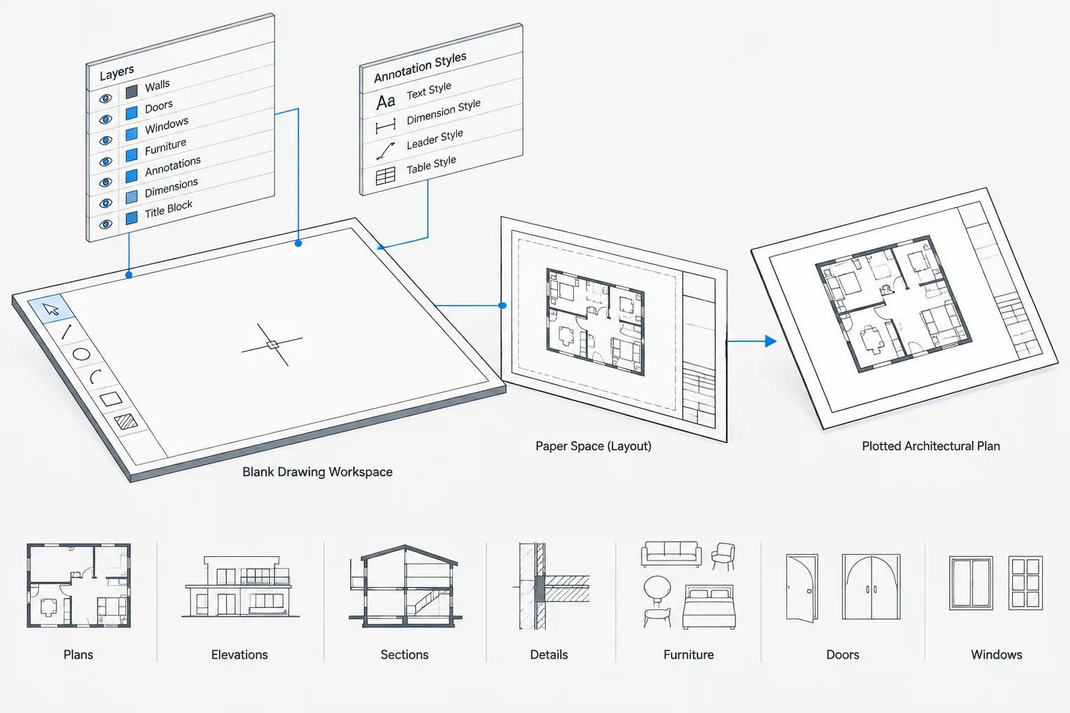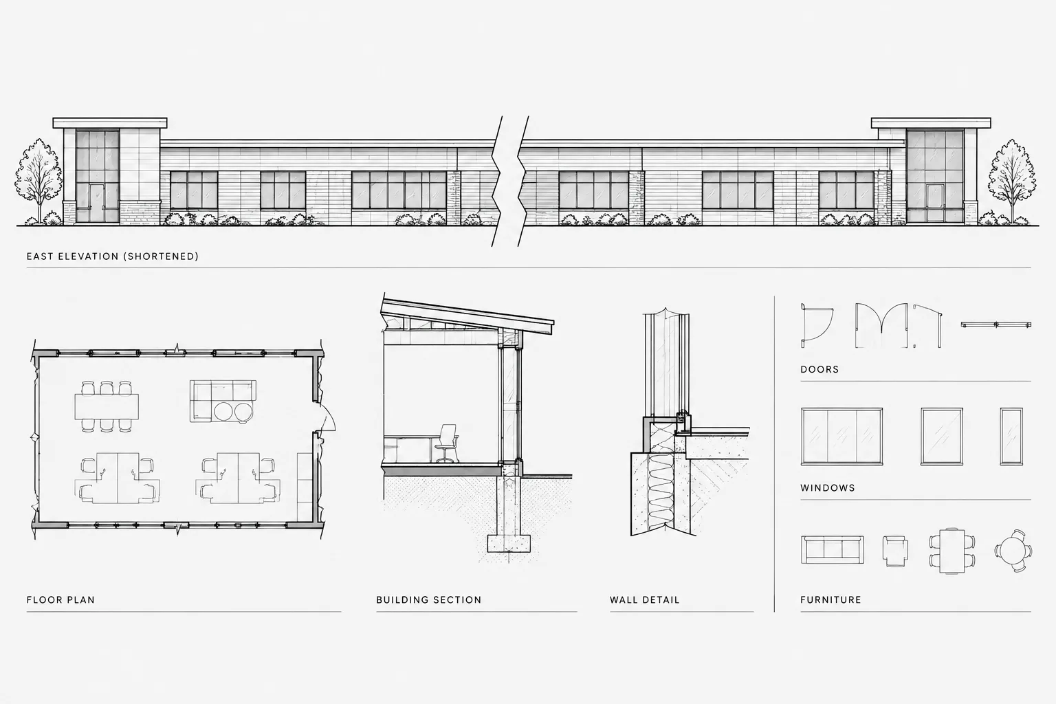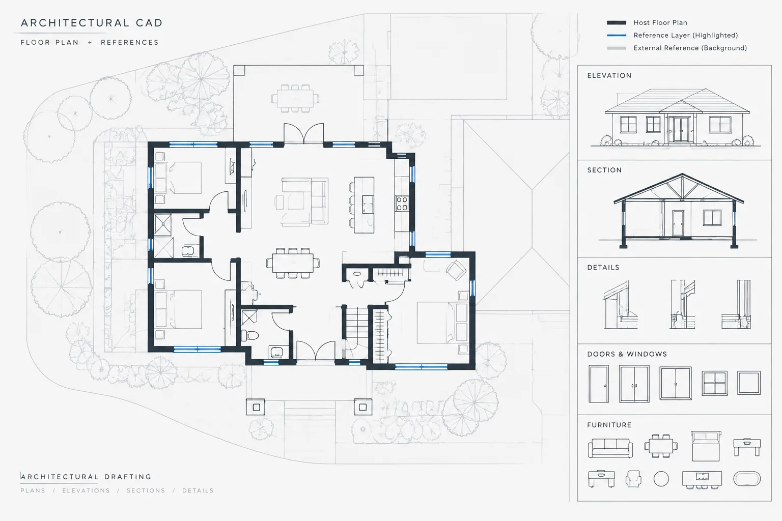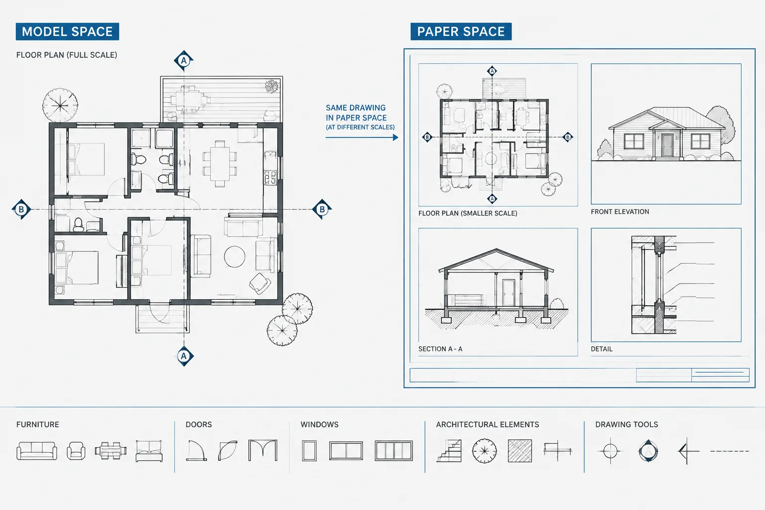
Window details in architectural CAD must connect product geometry with the surrounding wall, finishes, structure, and drawing references. This guide presents a practical coordination workflow for developing head, jamb, and sill details as a consistent set rather than as isolated drawings.
The discussion is intentionally system-neutral. Project teams should verify product information, assembly design, performance requirements, and consultant input before applying any detail to construction documents.
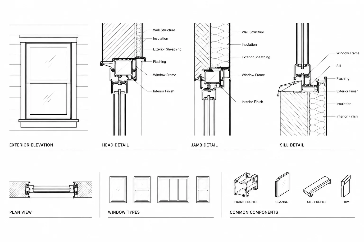
Window details translate a scheduled opening into buildable relationships among the frame, wall, structure, finishes, and environmental control layers. A clear window type elevation may describe the unit’s configuration, but it usually cannot explain every perimeter condition. Head, jamb, and sill details provide that additional information.
Drafting these details is not simply an exercise in enlarging a floor plan or wall section. Each view should communicate a specific interface, use information from verified project sources, and remain coordinated with plans, elevations, sections, schedules, and specifications. The following workflow focuses on organizing and reviewing window details in architectural CAD without assuming a particular wall system, product, or code requirement.
Start with the opening, not the detail sheet
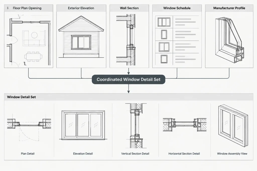
Before drawing detail geometry, identify where the window occurs and what surrounds it. The same scheduled window type may require different perimeter details when installed in different wall assemblies or structural conditions.
Review the relevant project information:
- Floor plans showing the opening, wall type, room relationship, and nearby construction.
- Exterior elevations showing window grouping, alignment, trim, joints, and adjacent materials.
- Building and wall sections showing floor edges, structure, ceilings, and wall depth.
- Window type elevations and schedules identifying unit configuration and project designations.
- Wall-type details describing substrates, insulation, cladding, and interior finishes.
- Structural information affecting lintels, supports, embeds, or opening framing.
- Verified manufacturer information for the selected or specified window system.
Treat imported manufacturer details as reference material rather than finished architectural details. Product drawings may show frame geometry accurately while omitting project-specific wall layers, finishes, perimeter transitions, or drawing references.
Build a window condition matrix
A condition matrix helps determine how many details are actually needed. It also prevents one generic detail from being referenced at locations where the surrounding construction is different.
| Condition | Questions to verify | Possible detail impact |
|---|---|---|
| Wall assembly | Does the window occur in more than one wall type? | Different perimeter layers or attachment context |
| Exterior finish | Do cladding, trim, or joint conditions change? | Different returns, clearances, or closures |
| Window family | Are frame profiles or operating types different? | Different frame geometry and manufacturer references |
| Opening support | Does the structural condition vary? | Different head or sill support coordination |
| Interior finish | Are there different jamb returns, stools, or wall finishes? | Different interior termination details |
| Window grouping | Is the unit isolated, paired, stacked, or part of a larger assembly? | Additional mullion or transition details |
Use the matrix to group genuinely equivalent conditions. Avoid creating unnecessary details for cosmetic differences, but do not combine conditions when doing so hides a meaningful construction change.
Establish a reliable CAD base
Use verified source geometry
Begin with the coordinated wall assembly and the correct window frame profile. If frame geometry comes from a manufacturer file, inspect its units, scale, layers, object types, and level of detail before bringing it into the project drawing. Remove irrelevant annotations and product-sheet graphics, but retain geometry needed to explain the interface.
Do not resize a proprietary frame profile merely to make it fit a preliminary wall sketch. Resolve discrepancies through design coordination and verified product information.
Draw the assembly by function
Separate the components logically so they can be controlled and reviewed. A project layer system might distinguish cut construction, beyond-view geometry, overhead or concealed items, membranes, insulation, sealants, annotations, and reference backgrounds. The exact layer names should follow the office or project standard.
Where practical, keep the architectural detail geometry independent from temporary consultant backgrounds. Referenced information can remain visible for coordination without becoming indistinguishable from architectural scope.
Choose deliberate detail boundaries
Show enough surrounding construction to explain the relationship. A window head detail may need part of the wall above and the opening support condition. A jamb detail should establish both the exterior and interior returns. A sill detail should show how the frame relates to the wall, interior finish, exterior finish, and supporting construction.
Use break lines or crop boundaries where the assembly continues. Avoid drawing large areas of repetitive wall construction that add drafting effort without improving understanding.
Coordinate the head, jamb, and sill as a set
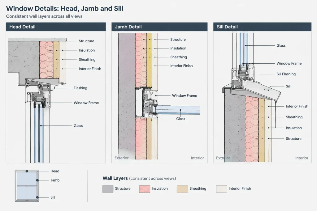
The three primary perimeter details should read as views of the same assembly rather than unrelated diagrams. Compare them side by side throughout development.
Head detail
Coordinate the top frame position, opening support, exterior finish termination, interior finish return, and any relevant concealed space above the opening. Confirm that the detail agrees with the window head elevation shown in the building section and exterior elevation.
Jamb detail
The jamb often provides the clearest horizontal relationship between frame and wall. Check the frame location within the opening, finish returns, adjacent cavity or insulation zones, cladding termination, and perimeter joint location. Also verify whether the plan uses the same frame position and wall thickness.
Sill detail
Coordinate the lower frame, support surface, interior sill treatment, exterior transition, and wall layers below. Sill geometry should be based on the selected assembly and verified project requirements rather than copied from a visually similar detail.
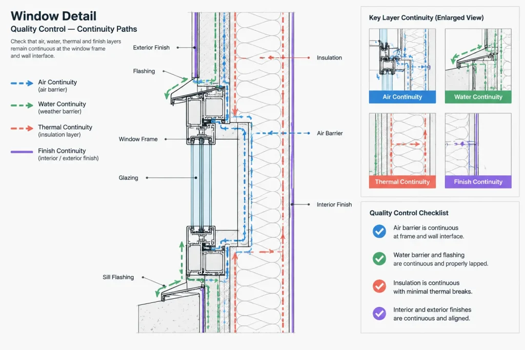
Trace important layers mentally—or with temporary colored polylines—around all three views. If a layer stops or changes position, the detail should make the transition understandable. This continuity review is especially useful for air, water, thermal, and finish control relationships, but the architect must confirm the actual materials and performance design for the project.
Use a clear graphic hierarchy
Window details contain many closely spaced components. Graphic hierarchy is therefore more important than adding excessive geometry.
- Use strong cut lines for primary construction intersected by the detail plane.
- Use lighter lines for objects seen beyond the cut.
- Apply poche or hatching selectively to distinguish major materials.
- Keep small proprietary profiles legible without allowing them to dominate the wall assembly.
- Use consistent symbols for membranes, sealants, insulation, and blocking where those conventions are established by the project.
- Place notes in open areas and use leaders that terminate unambiguously.
Test the detail at its intended plotted scale. Geometry that appears clear while zoomed in may merge into a dark patch on the sheet. Simplify features that do not contribute to construction communication, while preserving critical interfaces.
Reference details from the correct drawings
Detail callouts should originate from views that help the reader understand location and orientation. Head and sill details are commonly referenced from sections or elevations, while jamb details may be referenced from plans or enlarged plans. The appropriate source depends on the drawing set and the condition being explained.
Maintain a direct relationship among the callout, detail identifier, sheet location, window designation, and wall condition. If one detail applies to several openings, verify every referenced location rather than assuming that matching window tags guarantee matching perimeter construction.
Handle typical details carefully
A typical detail can reduce repetition, but the word “typical” does not resolve differences. Clearly define the scope of any repeated condition. A note may indicate that a detail applies to similar locations, but each location still requires review against its wall type, finish, structure, and window selection.
When conditions are nearly identical, consider using a base detail with clearly identified variations. This can be easier to maintain than duplicating complete details and allowing them to drift apart during revisions. However, a variation should not rely on vague notes that force the reader to guess which geometry changes.
Run a focused coordination check
Before issue, review window details as a connected group rather than checking each drawing in isolation.
- Compare frame position with the floor plan, enlarged plan, and wall section.
- Confirm that opening and window identifiers agree with the schedule.
- Check that wall layers align among the head, jamb, and sill.
- Verify interior and exterior finish names against the project documentation.
- Confirm that structural elements are consistent with current structural information.
- Review manufacturer-derived geometry against the selected system and current source material.
- Check that notes do not conflict with drawn geometry.
- Inspect callout references and sheet locations after details are moved or renumbered.
- Plot the sheet and review lineweights, hatches, masks, text, and leader clarity.
- Remove obsolete geometry and temporary coordination marks from the issued view.
Create details that remain maintainable
The best window detail set is not necessarily the one with the most lines. It is the set that clearly distinguishes recurring conditions, connects verified product information to project assemblies, and can be updated without creating contradictions.
Use shared base geometry or controlled source files where appropriate, but avoid dependencies that make individual details difficult to understand or issue. Record unresolved decisions through the project’s coordination process instead of hiding them behind generic notes. As wall types, finishes, or window selections change, return to the condition matrix and verify which details and references are affected.
A disciplined workflow turns window details into coordination tools. By starting with opening conditions, organizing verified geometry, checking continuity across head, jamb, and sill, and reviewing the completed sheet at print scale, the CAD drafter can produce details that are clearer, more consistent, and easier for the project team to maintain.
Use the detail set as a coordination record
Completed window details should document resolved relationships while making unresolved items easy to identify. If the frame selection, wall assembly, finish transition, or support condition remains under review, track that issue through the project coordination process rather than concealing it with generic geometry or ambiguous notes.
A useful final review starts with the drawing references and follows the information path to the detail. The reviewer should be able to locate the opening, identify its window and wall conditions, find the applicable perimeter details, and understand how those details relate to the adjacent construction.
Separate drafting errors from design questions
Some discrepancies can be corrected directly, such as mismatched tags, stale callouts, inconsistent linework, or duplicated notes. Others require a design decision or confirmation from the appropriate project participant. Distinguishing between these categories helps prevent an unverified assumption from becoming embedded in the drawing set.
- Drafting issue: The detail reference does not match the sheet location.
- Coordination issue: The wall section and jamb detail show different frame positions.
- Product issue: The referenced frame geometry does not match the current selected system.
- Design issue: The intended transition between wall layers has not been resolved.
- Scope issue: Architectural and consultant drawings assign the same interface differently.
Review changes by condition, not only by sheet
When a window, wall type, finish, or structural condition changes, search for every affected representation. The revision may extend beyond the detail sheet to plans, elevations, building sections, schedules, enlarged views, keynotes, and specifications. A condition-based review is more reliable than checking only the sheet where the change was first made.
Window details are most effective when they remain traceable, readable, and coordinated throughout revisions. The goal is not to show every product feature, but to communicate the interfaces needed to understand the project assembly and to flag information that still requires verification.
Frequently asked questions
What is the difference between a window type elevation and a window detail?
A window type elevation communicates the unit configuration and designation. A window detail explains how the frame meets the surrounding construction at a particular head, jamb, sill, mullion, or transition condition.
Can one window detail apply to every opening of the same type?
Not automatically. Openings with the same window designation may occur in different wall assemblies, finishes, structural conditions, or groupings. Confirm the surrounding construction before assigning a typical detail.
Should manufacturer CAD files be inserted directly into architectural details?
Manufacturer geometry can be a valuable reference, but it should be checked for units, scale, object types, layers, relevance, and consistency with the selected system. The architectural detail must still coordinate the product with project-specific construction.
How can head, jamb, and sill details be checked for continuity?
Compare the details side by side and trace corresponding wall, finish, insulation, membrane, joint, and frame relationships through each view. Temporary colored polylines can help reveal layers that shift, stop, or conflict.
When should a separate window detail be created?
Create a separate detail when a change in the wall assembly, frame family, finish transition, support condition, grouping, or interior return materially changes the construction relationship. Cosmetic differences alone may not require duplication.
What should be checked after a detail is moved or renumbered?
Review the detail identifier, sheet reference, source callouts, window and wall designations, related notes, and any references from plans, elevations, sections, or enlarged views.