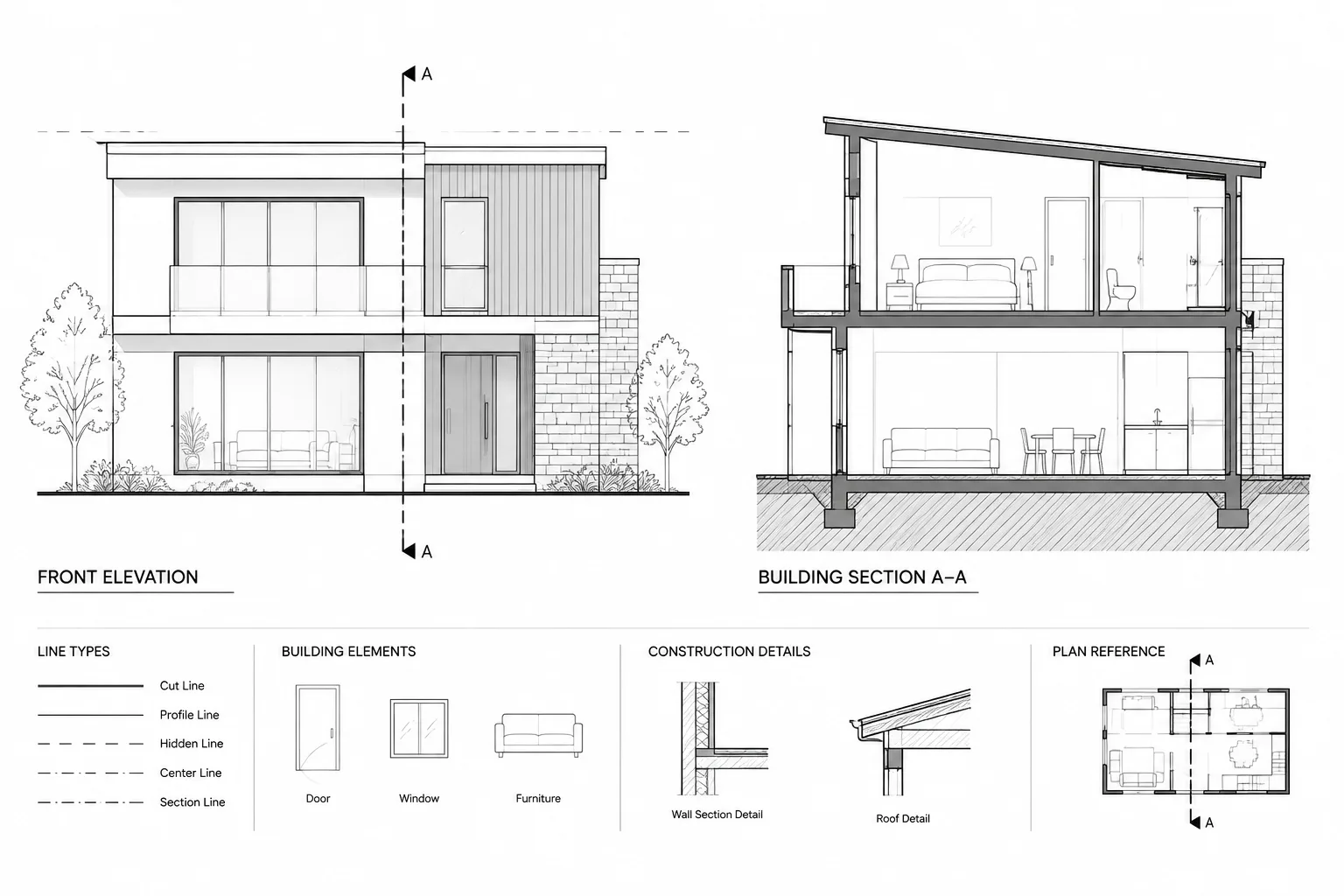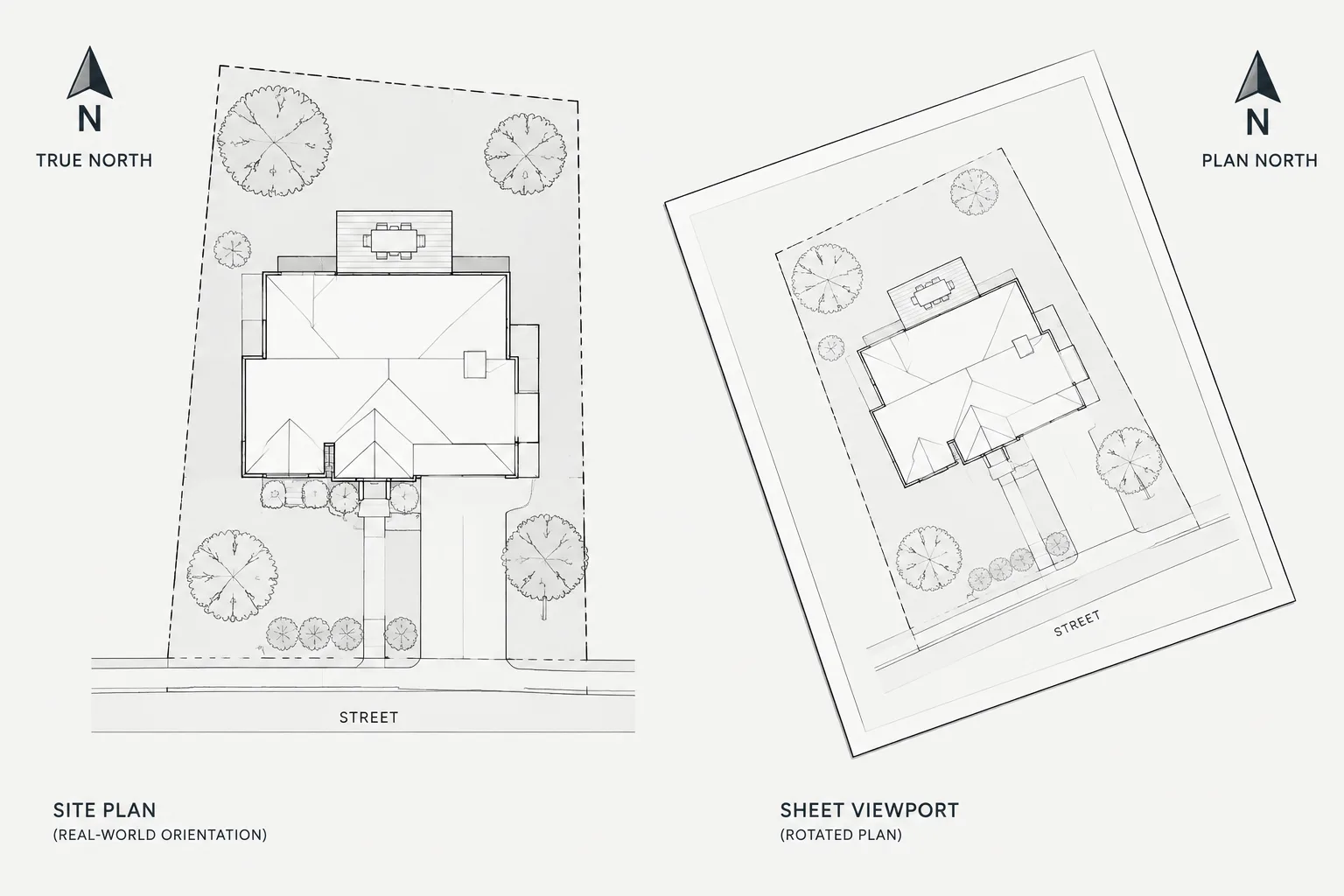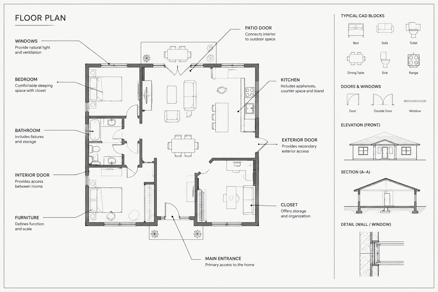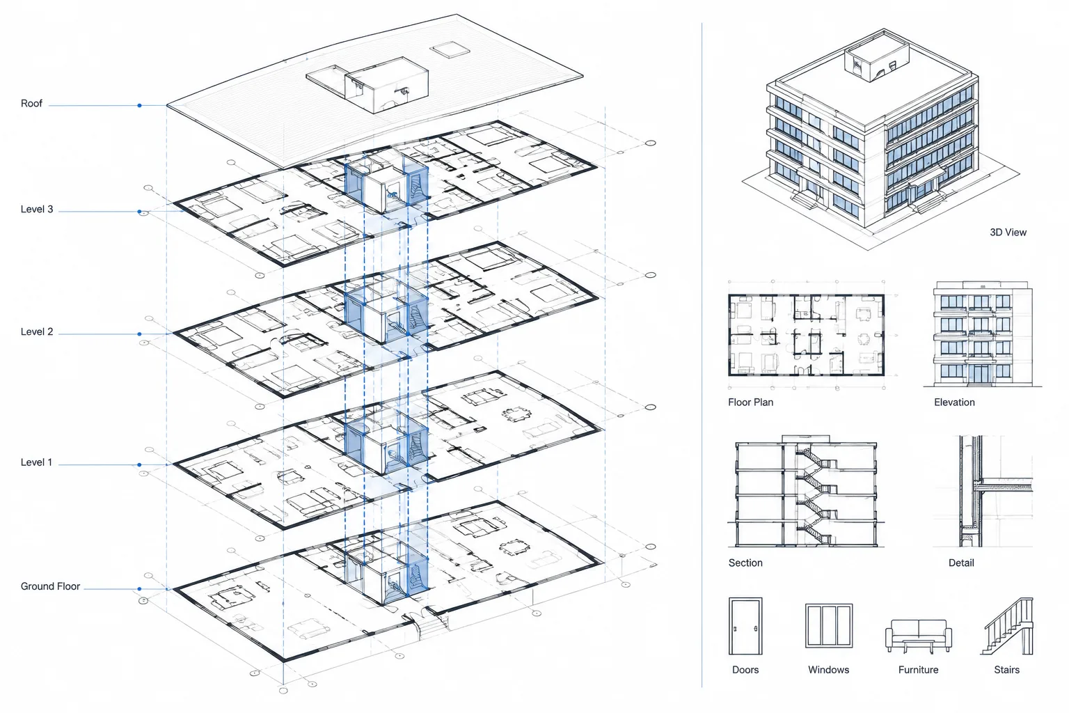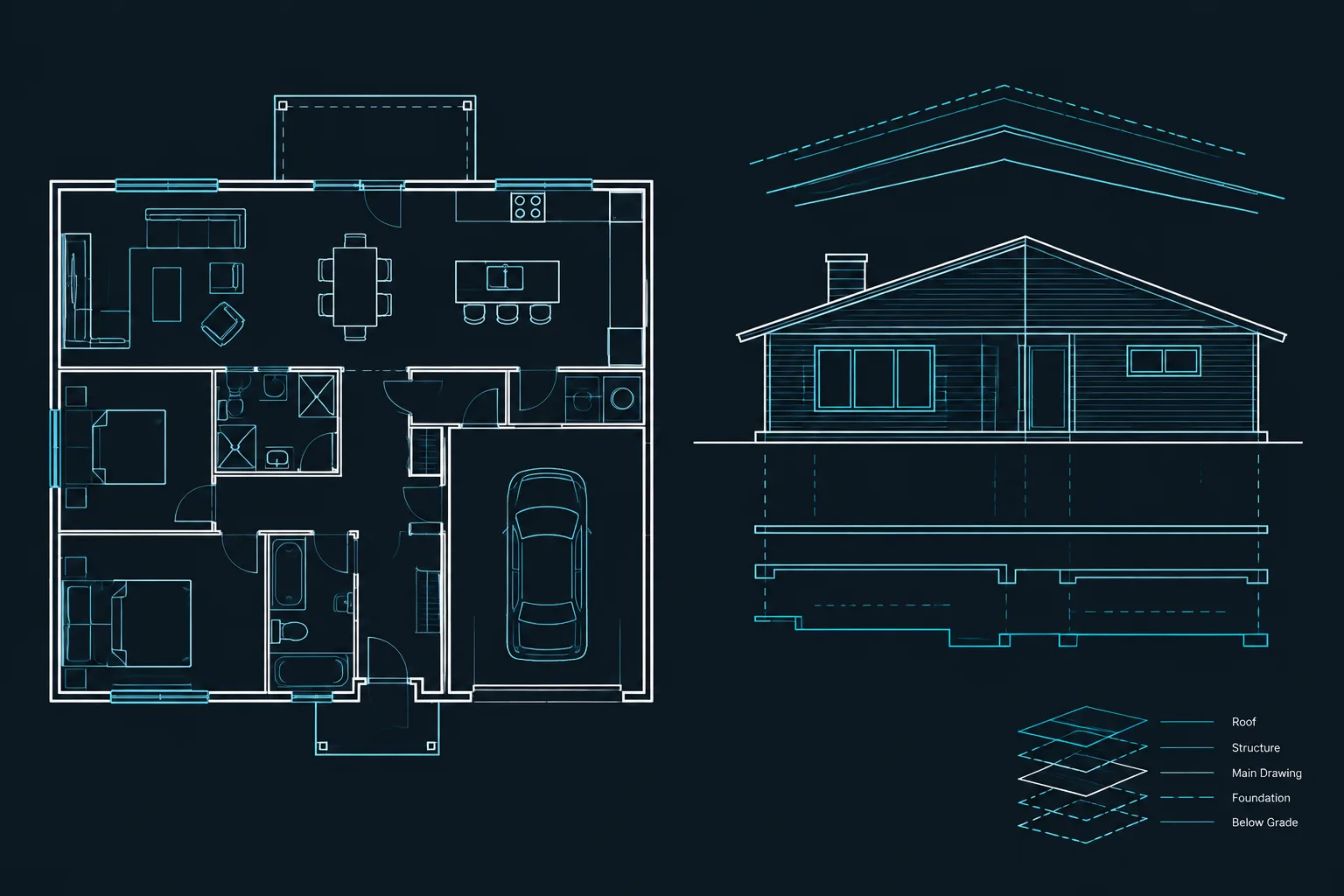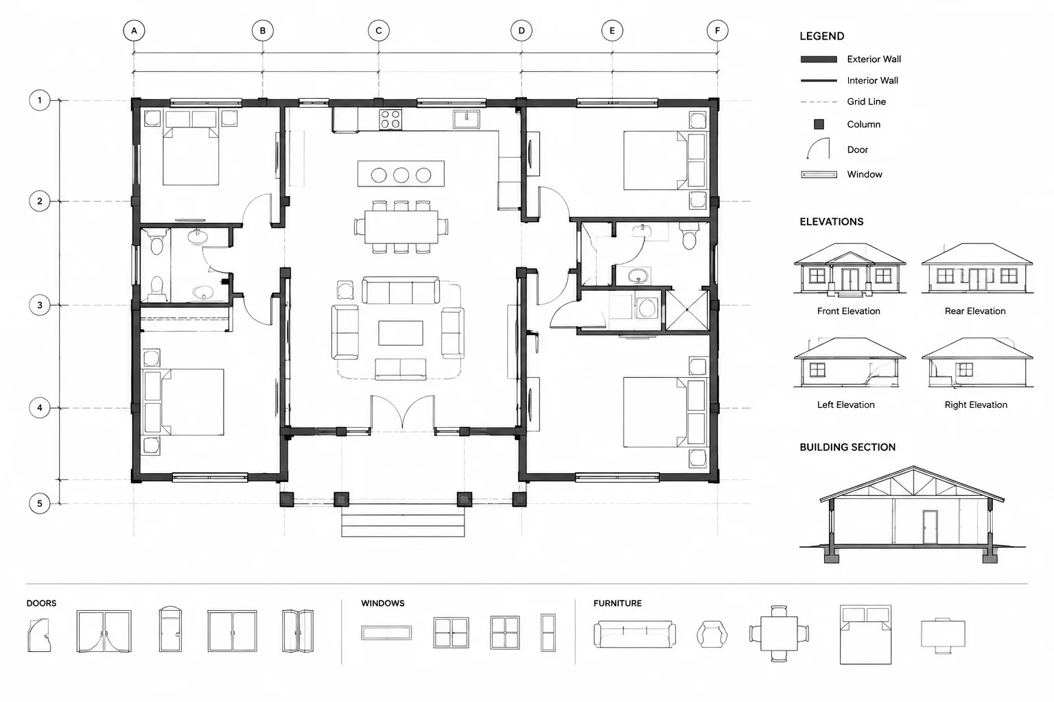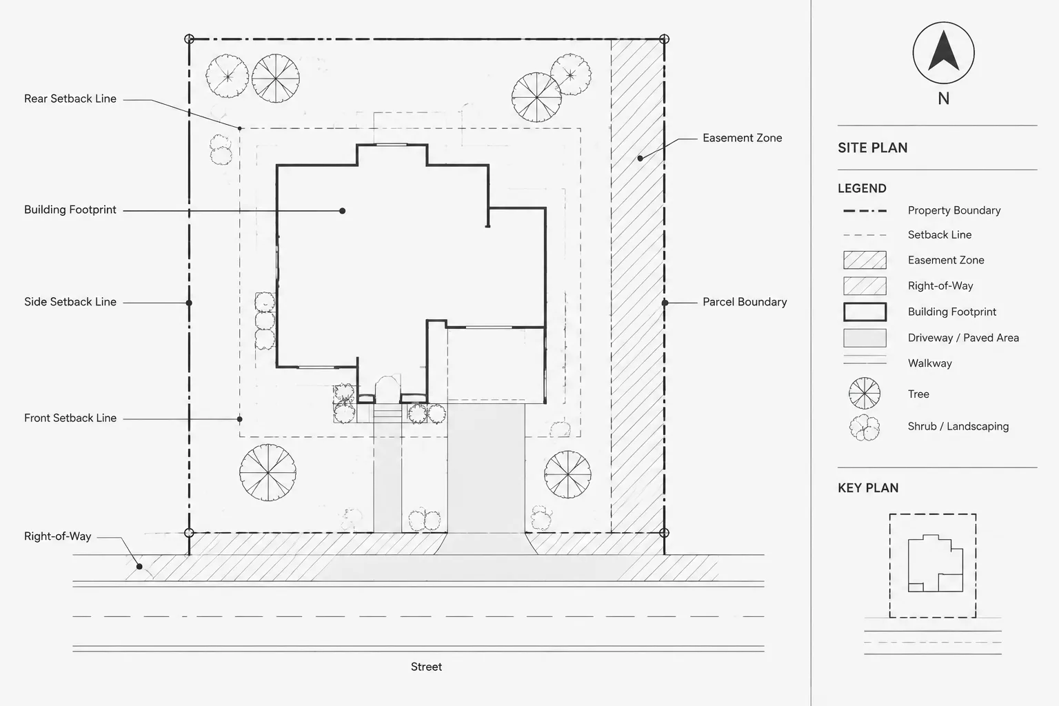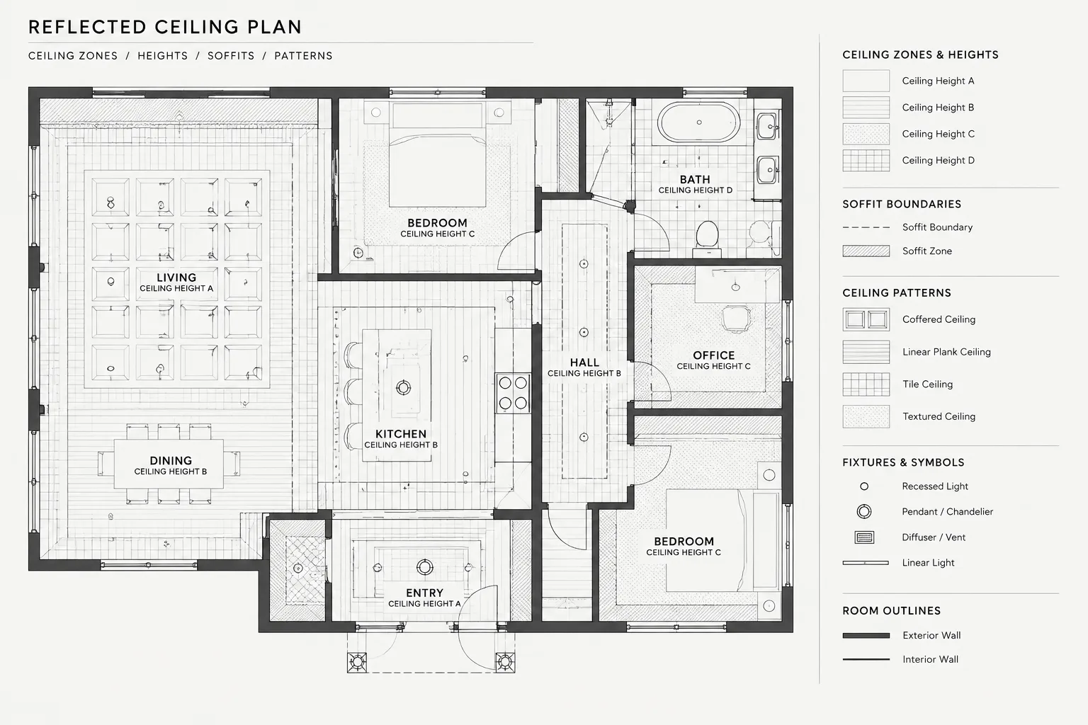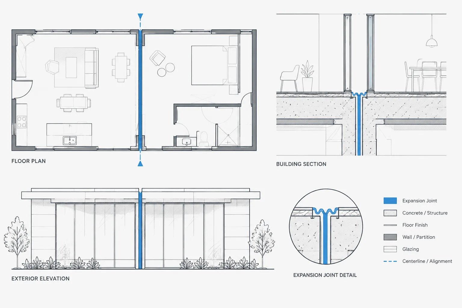
Drafting expansion joints in architectural CAD is primarily a coordination task. The linework must identify a continuous separation while remaining clear across drawings prepared at different scales and by different disciplines.
This guide explains how to establish controlled joint geometry, distinguish physical edges from symbolic annotation, coordinate affected assemblies, and review the completed drawing set. Project-specific locations, movement criteria, performance requirements, and product components must still be verified with the design team and applicable documentation.
Expansion joints can affect nearly every part of an architectural drawing set. A joint may pass through floors, walls, ceilings, roofs, finishes, and exterior assemblies while also interacting with structural framing and building services. If it appears only as a pair of lines on a floor plan, important coordination requirements can easily be missed.
A reliable CAD workflow treats the joint as a continuous building condition rather than an isolated symbol. Its location must remain consistent between plans, elevations, sections, details, and consultant backgrounds. The architectural drawings should also distinguish the joint itself from covers, seals, curbs, transitions, and other components used to complete the surrounding construction.
Understand What the Joint Represents
An expansion joint separates portions of a building so they can move relative to one another. The required movement, joint geometry, structural separation, and suitable joint system must come from the project design team and verified product information. A generic CAD block should not be used to determine any of these requirements.
Do not automatically treat every break in a material as an expansion joint. Drawings may also contain control joints, construction joints, isolation joints, reveals, sealant joints, or finish transitions. These conditions can have different purposes and may not continue through the same assemblies.
Before drafting, identify the intended condition and its scope:
- Does the separation extend through the structural system?
- Which floors, walls, roofs, ceilings, and finishes does it cross?
- Is the joint exposed, concealed, or covered by a manufactured assembly?
- Does its path remain straight, or does it offset around building elements?
- Who is responsible for establishing its location and movement criteria?
- Which disciplines need to accommodate or avoid the joint?
Answers to these questions determine how the condition should be represented. They also prevent a drafter from converting an unresolved design issue into misleadingly precise linework.
Establish a Single Coordinated Joint Path
Begin by locating the joint in the primary plan geometry. Depending on the office workflow, that may be an architectural base plan, a referenced structural plan, or another controlled background. The joint path should have a clear source rather than being redrawn independently in every file.
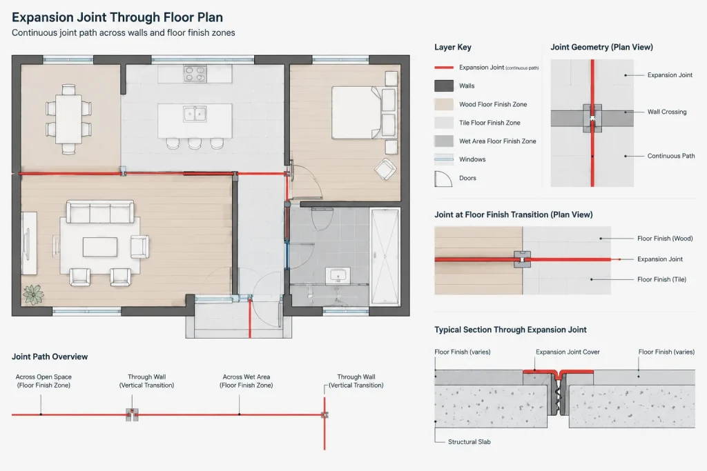
Keep the controlling geometry simple. A polyline or similarly manageable object is often easier to compare, offset, and update than a collection of disconnected segments. Place it on a dedicated layer or a clearly identified layer shared with comparable joint information. Avoid placing the controlling linework on a general wall, floor, or annotation layer.
If the visible joint has width, determine whether the drawing needs to show both edges or only a symbolic centerline. That choice may vary by view scale and drawing purpose. A small-scale overall plan may use a simplified symbol, while an enlarged plan or detail may show the actual opening, cover limits, adjacent finishes, and supporting construction.
Use references instead of duplicate geometry
Where possible, display the same coordinated path through external references or another controlled reference method. If separate plan files must contain local representations, establish a checking procedure so changes to the primary geometry are carried into every affected drawing.
Do not rely on visual similarity alone. Joint lines that appear aligned at one zoom level may be offset, broken, or based on different coordinates. Use CAD comparison, object snaps, temporary construction lines, or measured checks to confirm alignment.
Choose Clear Plan Graphics
The plan representation should communicate the joint without overpowering nearby walls, doors, fixtures, and dimensions. The exact graphic convention depends on the office standard and the scale of the view, but consistency is more important than decorative complexity.
A typical plan may include:
- Linework showing the joint location or physical opening.
- A distinct linetype or symbol where the joint is represented diagrammatically.
- A text note, keynote, or joint designation.
- Detail references at representative conditions and changes in assembly.
- Breaks or transitions in floor patterns where finishes terminate at the joint.
- References to enlarged plans when the condition cannot be explained clearly at the overall plan scale.
Keep symbols separate from physical geometry. For example, a zigzag joint symbol may improve recognition, but it should not be mistaken for the actual edges of the opening. Place symbolic graphics on an annotation layer when they need independent visibility or plotting control.
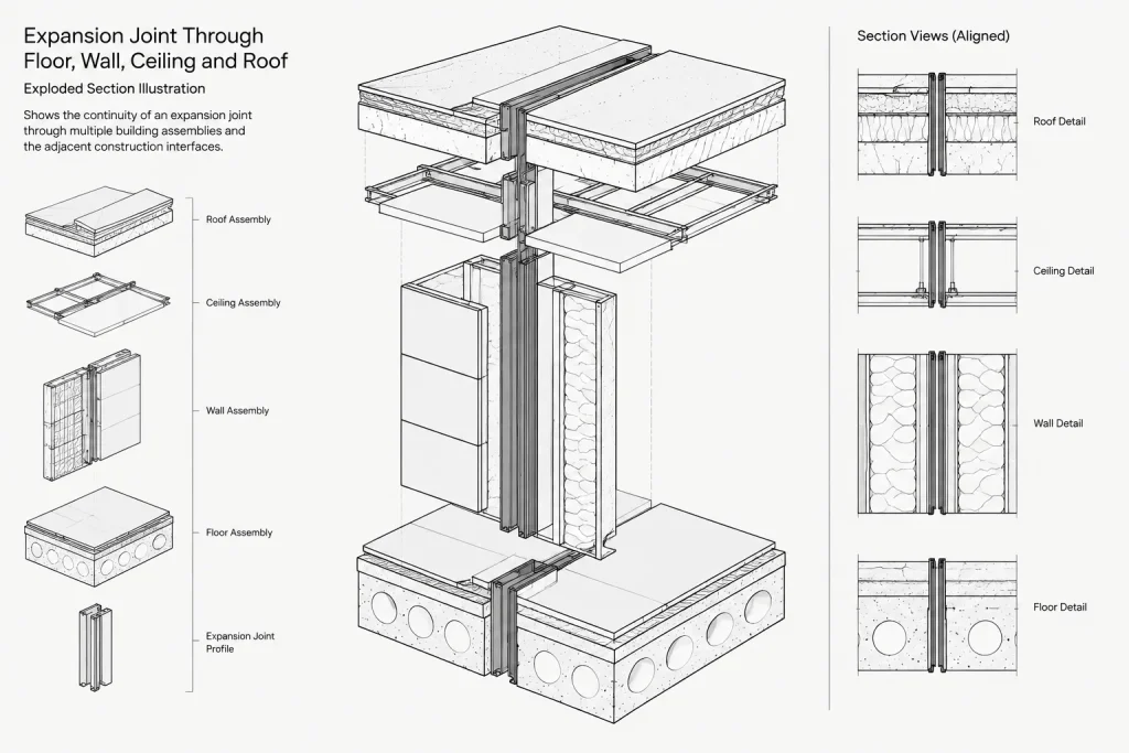
Coordinate Every View the Joint Crosses
A joint shown in plan should be traced through the full drawing set. The following review table can be used as a coordination checklist.
| Drawing type | Items to verify |
|---|---|
| Floor plans | Joint path, wall interruptions, floor finish terminations, door conflicts, and references to enlarged views. |
| Reflected ceiling plans | Ceiling breaks, grid termination, soffits, lighting conflicts, access requirements, and joint cover visibility. |
| Roof plans | Roof membrane transitions, curbs, drainage relationships, parapets, and changes in roof elevation. |
| Exterior elevations | Vertical continuity, facade panel divisions, reveals, cover profiles, and alignment with openings. |
| Building sections | Continuity through floors and roof, relative assembly depths, and references to detailed conditions. |
| Interior elevations | Finish interruptions, wall protection, base, trim, cabinetry, and exposed covers. |
| Details | Adjacent substrates, finish edges, support conditions, seals, covers, and interfaces with other assemblies. |
When the joint changes direction or crosses an unusual condition, a generic typical detail may not be enough. Corners, intersections, wall-to-floor transitions, roof-to-wall transitions, and changes in finish can require separate drawings or explicit references.
Draft Sections and Details from the Assembly Outward
In sections and details, start with the verified separation between the major building assemblies. Then add adjacent components in their construction order. This reduces the chance of drawing a cover or finish transition without showing the opening it is intended to accommodate.
A detail may need to identify the following relationships:
- Edges of structural or supporting construction.
- Wall, floor, ceiling, roof, or facade build-up on each side.
- Water, air, vapor, insulation, or fire-resistive continuity where applicable to the project.
- Joint seals, covers, frames, anchors, or backing components based on verified information.
- Finish termination and protection at exposed edges.
- Access or replacement considerations for visible components.
Avoid illustrating performance that has not been designed or confirmed. For example, a generic hatch or sealant shape should not imply a tested fire-resistance, waterproofing, or structural capability. If a performance requirement applies, coordinate the detail with the responsible consultant and the selected assembly documentation.
Manage Layers, Blocks, and Annotation
Use layers that allow physical joint geometry, joint symbols, text, and reference information to be controlled separately. This makes it easier to simplify an overall plan while retaining more complete graphics in enlarged plans and details.
Blocks can be useful for repeated joint tags, directional markers, or detail-reference symbols. Keep the block insertion point logically related to the joint so it can be positioned accurately. If attributes are used, limit them to information the team can maintain consistently, such as a joint identifier or detail reference.
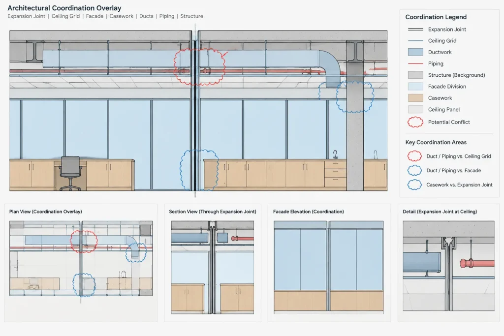
Do not build critical geometry into a tag block merely for convenience. If the joint location changes, hidden or embedded linework can remain behind and create contradictory documentation. The actual path should remain editable and easy to inspect.
Check Coordination with Other Disciplines
Expansion joints frequently cross systems that cannot simply continue through the separation. Structural framing, piping, ductwork, cable routes, fire protection, ceilings, and facade supports may all require specific accommodation. The architectural drawings do not need to design every discipline’s solution, but they should provide a consistent location for coordination.
Overlay current consultant backgrounds and review the joint along its full length. Pay particular attention to vertical risers, major equipment connections, recessed fixtures, floor drains, roof drains, built-in casework, and facade attachments. Mark unresolved conflicts rather than adjusting the architectural joint locally without authorization.
If the structural joint location changes, treat it as a coordinated revision. Update plans, reflected ceiling plans, roof plans, elevations, sections, details, finish information, and relevant references as one controlled task.
Run a Focused Quality-Control Review
Before issuing the drawings, isolate or highlight the expansion-joint layers and follow each joint through the project. A useful review sequence is:
- Confirm that the plan path matches the current controlling background.
- Check that the joint continues through every applicable level.
- Compare plan locations with elevations and sections.
- Review interruptions in walls, ceilings, roofs, and finish patterns.
- Verify that detail references point to the intended condition.
- Confirm that duplicated tags and notes use consistent terminology.
- Look for doors, fixtures, casework, equipment, and services crossing the joint.
- Check plotted output to ensure symbols and lines remain legible at sheet scale.
- Remove abandoned geometry left from earlier joint locations.
The most useful architectural CAD drawing is not the one with the most elaborate joint symbol. It is the one that makes the separation easy to locate, follows it consistently through the building, and directs the reader to verified information for each construction condition.
Turn Joint Coordination into a Traceable Workflow
A practical way to manage an expansion joint is to separate the work into controlled geometry, view-specific representation, and supporting information. The controlled geometry establishes where the joint runs. View-specific graphics determine how that path appears in plans, elevations, sections, and details. Notes, tags, and references then direct the reader to the appropriate construction information.
This separation helps prevent a common documentation problem: revising a visible symbol without updating the underlying joint path or related details. It also makes quality-control reviews more focused because the team can inspect location, graphics, and annotation as distinct drawing components.
Record unresolved conditions without guessing
If the joint reaches an assembly that has not been resolved, mark the location for coordination rather than completing the detail with assumed components. The drawing can identify the interface and responsible discipline without implying an unverified solution.
Useful coordination records may include:
- The source used to establish the current joint path.
- The views and details affected by a location change.
- Conflicts awaiting consultant or design-team direction.
- Product-dependent components that require verified information.
- Annotations or references that must be updated before issue.
Review both model space and plotted sheets
Accurate CAD geometry does not automatically produce clear construction documents. Check the source linework for alignment and continuity, then review the plotted presentation for hierarchy, legibility, and conflicts with hatching, dimensions, tags, or reference markers.
The final documentation should let a reader follow the joint through the building without confusing its physical boundaries, cover components, finish transitions, or symbolic graphics.
Frequently Asked Questions
Should an expansion joint be drawn as a centerline or as two edges?
The appropriate representation depends on the view purpose and drawing scale. A general plan may use a simplified centerline or symbol, while an enlarged plan or detail may need to show the physical opening, adjacent construction, and cover limits. The graphic convention should remain consistent and should not misrepresent the actual condition.
Can the same expansion-joint block be used throughout a drawing set?
A repeated block can work for tags or reference symbols, but it should not replace the controlled joint geometry. Plans, sections, elevations, and details may require different representations because they communicate different aspects of the assembly.
What is the difference between an expansion joint and a finish transition?
An expansion joint separates building portions to permit relative movement. A finish transition addresses a change between finish materials and may not continue through the supporting construction. The drawings should not use the terms or symbols interchangeably unless the project design confirms that the conditions coincide.
Who determines the expansion-joint location and required movement?
Those decisions must come from the responsible project design team, coordinated consultants, and verified assembly information. Architectural CAD linework should document approved criteria rather than establish structural separation or movement requirements independently.
What should be checked when an expansion joint moves during design?
Review every affected plan, reflected ceiling plan, roof plan, elevation, section, detail, finish condition, annotation, and consultant background. Also remove abandoned geometry so an earlier location cannot be mistaken for current information.
How should unresolved service crossings be shown?
Identify the conflict for coordination and avoid drawing an assumed connection across the joint. The responsible discipline should determine how its system accommodates the separation, while the architectural documents maintain a consistent joint location.