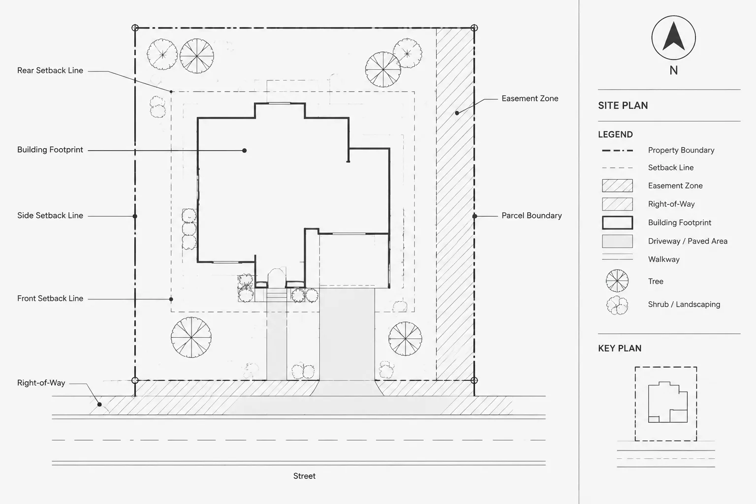
Drafting property lines, easements, and setbacks in CAD requires more than selecting different linetypes. Each element may come from a different document, and each has a different role in site planning and design coordination.
This guide explains how to preserve verified source geometry, separate derived planning lines, organize layers and annotation, and review the resulting architectural site plan without implying that CAD linework establishes legal boundaries.
Property lines, easements, setbacks, and rights-of-way can appear deceptively simple on an architectural site plan. Each may be represented by a line and a label, but the lines do not mean the same thing. They can come from different source documents, carry different levels of authority, and affect different parts of a proposed design.
A reliable CAD workflow must preserve those distinctions. The goal is not merely to trace boundaries. It is to create a readable site-plan framework that allows architects, surveyors, civil consultants, and reviewers to understand where each line originated and how it relates to the building layout.
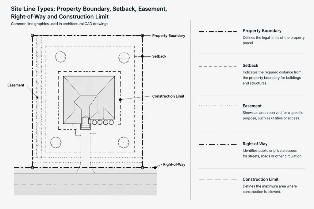
Understand the Line Types Before Drafting
Begin by identifying what each site line represents. Avoid treating every dashed line near a parcel boundary as a setback.
| Site-plan element | General meaning | Typical coordination concern |
|---|---|---|
| Property line | The documented boundary of a parcel or lot | Must agree with the current survey or other verified boundary source |
| Easement | An area where a party may hold defined access, utility, drainage, or other rights | Restrictions vary; the easement document must be reviewed |
| Setback line | A line derived from a planning, zoning, deed, or project-specific requirement | The controlling rule and measurement basis must be confirmed |
| Right-of-way | An area associated with public or private transportation and access interests | Do not assume it matches the visible curb, pavement edge, or property line |
| Construction limit | A project-defined boundary for anticipated work or disturbance | Should not be confused with a legal or regulatory boundary |
| Survey control or monument | A documented point used to establish or verify surveyed geometry | Should remain tied to survey information rather than redrawn approximately |
This classification matters because a property line is normally source geometry, while a setback may be derived geometry. An easement may have its own bearings, offsets, curves, or recorded description. Keeping these categories separate makes revisions and verification much easier.
Start with the Best Available Source
Use a current survey or consultant file when one is available. A tax map, assessor graphic, planning diagram, old PDF, or aerial image may help with early studies, but it should not automatically be treated as a surveyed boundary.
Before using incoming geometry, review:
- The drawing units and insertion scale
- The file coordinate system or project origin
- Whether the geometry has been rotated for sheet presentation
- The survey date and visible revision information
- Whether lines are complete polylines, separate segments, or graphical approximations
- Any discrepancy between the CAD file, signed survey, title information, and consultant backgrounds
Do not force questionable source files to fit the architectural plan by stretching or independently moving individual boundary segments. If the site background does not align, determine whether the problem is scale, units, coordinates, rotation, or outdated information. Record unresolved discrepancies and send them to the appropriate project professional.
Separate Source Geometry from Architectural Interpretation
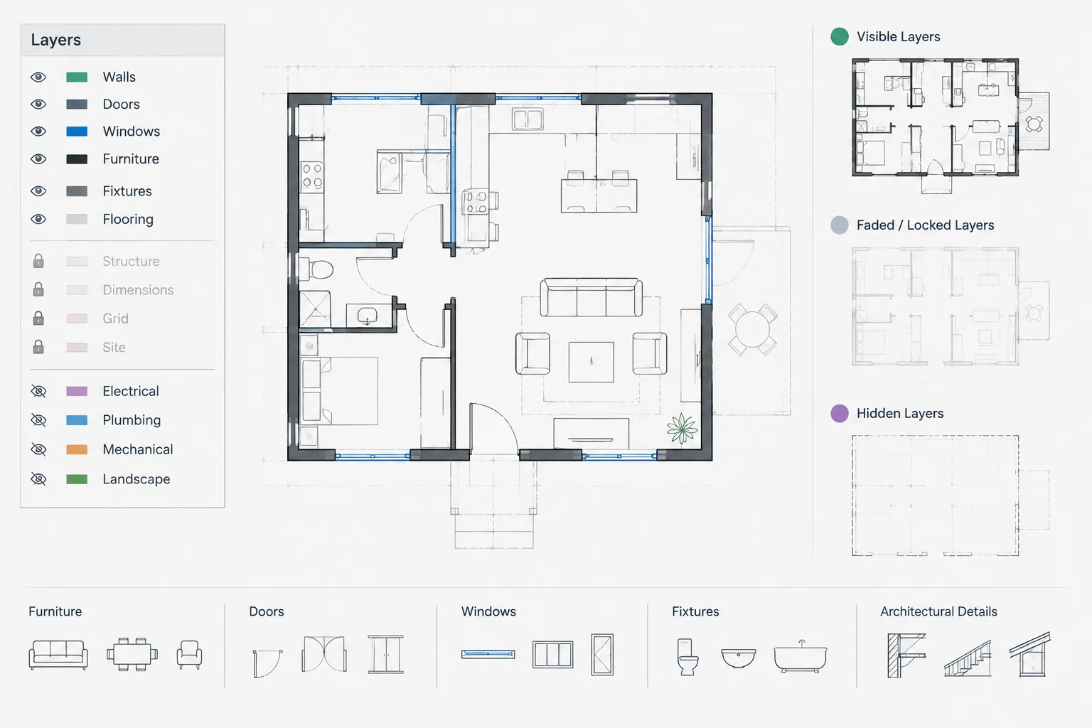
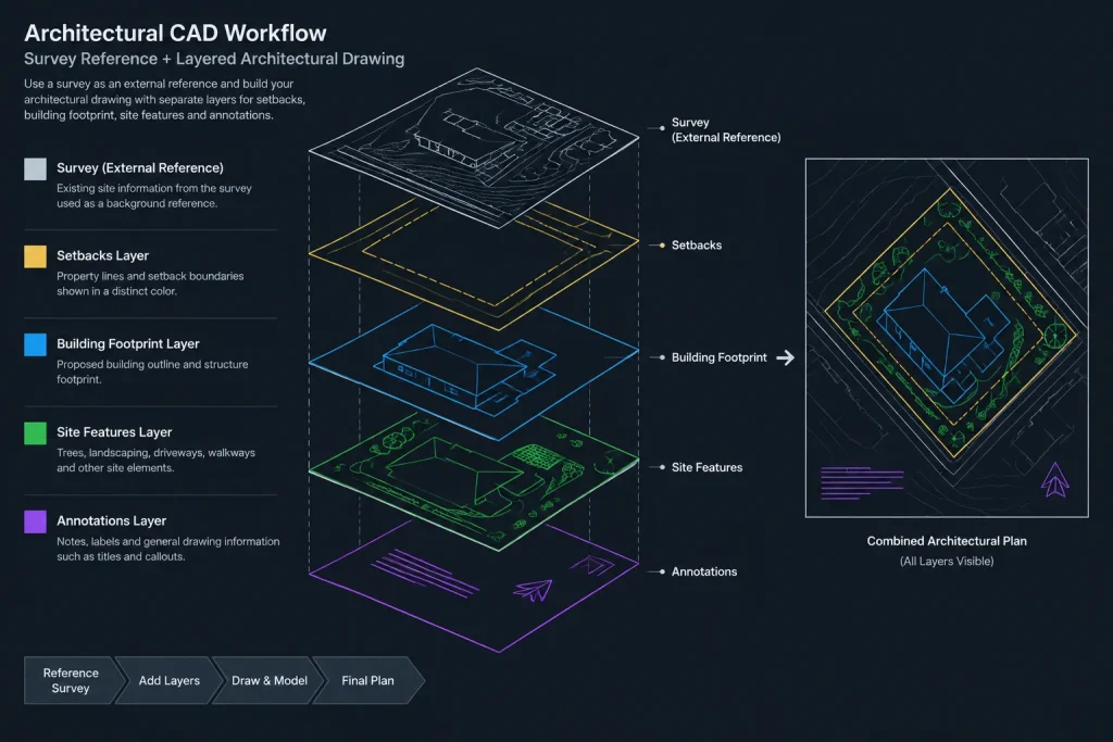
A useful CAD structure distinguishes imported or referenced survey information from lines created by the architectural team. One practical approach is to retain the survey as an external reference and draw project-specific setback or study lines on separate architectural layers.
For example, the layer system may distinguish:
- Survey property boundaries
- Survey easements
- Survey monuments or control points
- Architectural setback lines
- Rights-of-way
- Construction or disturbance limits
- Site-plan labels and dimensions
- Unverified study geometry
The exact layer names should follow the project template. The important principle is traceability. A user should be able to determine which geometry came from a survey and which geometry was calculated, interpreted, or added for design purposes.
Build Clean Boundary Geometry
Where editable boundary geometry is required, use connected linework that can be checked systematically. Closed polylines can be useful for parcel outlines and bounded zones, but closure alone does not prove that a legal boundary is correct.
Inspect the geometry for:
- Small gaps between boundary segments
- Overlapping or duplicated lines
- Unintended arcs or flattened curves
- Segments placed at slightly different elevations
- Rounded coordinates introduced during tracing
- Disconnected labels or dimensions left behind after revisions
Do not simplify curved boundaries merely to make drafting easier. If the source describes a curve, retain the verified curve geometry or reference the survey rather than replacing it with an approximate chord.
Create Setbacks as Derived Geometry
A setback line is often generated from another controlling line, but the correct reference is not always the apparent parcel edge. Depending on the governing document, measurement may relate to a property line, right-of-way, street line, easement edge, shoreline reference, or another defined feature. Confirm the basis before creating an offset.
Once the basis is verified, place the setback on its own layer and identify it clearly. Avoid embedding the setback into the property-line block or combining both into one polyline. Separate objects allow the boundary source to remain unchanged when a planning interpretation is revised.
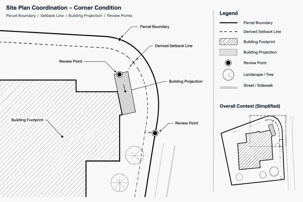
Offset tools can create initial geometry, but they do not resolve complex corners automatically. At irregular parcels, curved frontages, or lots with multiple street relationships, inspect every transition. Trimmed corners and intersecting offsets may need deliberate cleanup based on the confirmed planning interpretation.
Represent Easements Without Overstating Their Meaning
Easements should be shown according to the available documentation. Some are defined as strips parallel to a boundary; others follow utilities, access routes, drainage features, or individually described limits. A generic dashed rectangle should not replace a verified description.
Use labels that identify the easement by its documented purpose or reference when that information is available. If the limits are preliminary or taken from an unverified source, communicate that status in the working drawing and project coordination notes.
Do not infer that construction is allowed or prohibited solely because an easement appears on the plan. The underlying document and project-specific review determine its effect.
Use a Clear Graphic Hierarchy
Legal and planning lines must be noticeable without overpowering the proposed design. Property boundaries commonly need stronger emphasis than secondary setback or easement lines, while existing survey features may be screened back to support readability.
Differentiate line types with more than color alone. CAD colors may plot differently, and printed sets may be monochrome. Combine appropriate linetypes, lineweights, labels, and spacing so each category remains recognizable in a PDF or printed sheet.
Check linetype appearance at the intended viewport scale. A dashed line that looks distinct in model space may plot as nearly continuous or become visually fragmented. Avoid relying on extremely dense patterns that obscure corners and intersections.
Coordinate Labels and Dimensions
Place labels adjacent to their corresponding lines without covering bearings, dimensions, monuments, building outlines, or utility information. Repeating a label along a long or irregular line can be clearer than using a single note with a distant leader.
Dimensions should serve a defined purpose. Architectural site plans may need relationships such as the proposed building to a property line or setback, but they should not casually recreate survey data. Preserve survey bearings and distances from the verified source instead of retyping them unless project procedures require editable annotation and include a checking process.
When the site plan is rotated for presentation, confirm that north arrows, bearings, coordinate labels, and dimensions still communicate the correct orientation. View rotation should not alter the underlying geometry.
Coordinate Building Placement Against the Site Framework
Once the site lines are organized, use them as a coordination framework for the building footprint, projections, site walls, stairs, ramps, canopies, paving, parking, utilities, and landscape elements. Do not check only the main exterior wall face. Roof overhangs, equipment pads, below-grade elements, and other projections may require separate review depending on the applicable documents.
A useful review sequence is:
- Freeze unrelated annotation and display the verified site framework.
- Confirm that the architectural building origin and survey reference remain aligned.
- Inspect the entire building perimeter at a close working scale.
- Review exterior features that extend beyond the primary wall outline.
- Compare architectural, civil, landscape, and utility backgrounds.
- Mark uncertain conditions rather than resolving them by assumption.
Quality-Control Checks Before Issue
Before publishing the site plan, perform both a geometric review and a sheet review.
- Confirm that referenced survey files are current and resolve correctly.
- Verify drawing units, scale, origin, and rotation.
- Check that property lines have not been moved during design revisions.
- Confirm that setback lines use the approved measurement basis.
- Review irregular corners, curves, and frontage conditions.
- Look for duplicate, broken, or overlapping linework.
- Compare easement labels with the available source documents.
- Check building projections and site features near controlling lines.
- Plot the sheet and verify linetype, lineweight, and annotation readability.
- Identify unresolved discrepancies in the project’s issue or coordination process.
Keep Legal Boundaries Traceable
The strongest CAD workflow treats property and easement information as controlled source material rather than ordinary background graphics. Preserve the source, separate derived lines, label interpretations clearly, and avoid making unsupported corrections.
Architectural CAD can organize and communicate the site framework, but it does not establish legal boundaries or determine the meaning of recorded restrictions. Those conclusions require the appropriate survey, title, planning, and professional review. A well-structured drawing makes that review easier by showing exactly what came from where and how the proposed design relates to it.
Manage Revisions Without Losing the Source Trail
Site information may change as updated surveys, title documents, consultant backgrounds, or planning interpretations become available. A revision workflow should make it possible to identify what changed without obscuring the previously issued basis.
When replacement information arrives, compare it with the current CAD background before updating architectural geometry. Review parcel corners, curves, easement limits, rights-of-way, monuments, orientation, and the relationship between the site framework and building origin. Avoid replacing a reference file and assuming that every dependent line remains valid.
Classify the Status of Site Linework
Clear status labels help prevent preliminary information from being mistaken for verified geometry. Project teams can distinguish between:
- Referenced source geometry: Information retained from a survey or consultant file.
- Derived geometry: Setbacks or other lines created from a confirmed controlling feature.
- Design coordination geometry: Building limits, study areas, or construction boundaries created for the project.
- Unresolved geometry: Information awaiting confirmation because source documents conflict or remain incomplete.
The wording and layer structure should follow the project’s established procedures. The key is to communicate status without presenting an assumption as a surveyed or legally established condition.
Check Dependencies After Every Site Update
A property-line revision can affect more than the visible parcel outline. Review setback offsets, building clearances, site dimensions, leaders, hatches, area boundaries, parking layouts, utility coordination, landscape geometry, and notes that depend on the changed linework.
Derived objects should remain separate enough to be checked or recreated from the controlling source. If a setback was manually edited after an offset operation, document the reason so a later drafter does not treat the adjustment as accidental.
Prepare the CAD File for Consultant Handoff
Before sharing the architectural site plan, remove ambiguity about the drawing basis. Keep source references identifiable, retain the project origin, and avoid unexplained movement or rotation of survey geometry. If presentation requires a rotated view, use a method that preserves the underlying coordinate relationship.
A practical handoff review should confirm that:
- Referenced files are named and organized consistently.
- Property lines and survey control remain distinguishable from architectural additions.
- Setbacks identify the feature from which they were derived when clarification is necessary.
- Easement labels agree with the available documentation.
- Unverified or disputed conditions are visibly flagged for coordination.
- Linework remains readable when plotted rather than only when viewed in color on screen.
This approach allows another professional to understand the site framework without reverse-engineering the drafting history or assuming that every line carries the same authority.
Frequently Asked Questions
Should a property line be redrawn in the architectural CAD file?
Use the verified survey or consultant geometry whenever possible. If editable architectural linework is required, keep it traceable to the source and avoid approximating, stretching, or independently correcting the boundary.
Can a setback be created by simply offsetting the property line?
Only after confirming that the property line is the controlling measurement basis. The applicable document may define the setback from another feature, and irregular corners or curves may require additional interpretation and review.
Are easements always parallel to property lines?
No. An easement may follow a boundary, utility route, access path, drainage feature, or separately described area. Draft its limits from the available documentation rather than assuming a standard shape.
Should property lines, easements, and setbacks share a layer?
Separate layers are generally more useful because they support independent display, checking, plotting, and revision. Layer names should follow the project template while preserving the distinction between source and derived geometry.
How should uncertain site information be shown?
Keep uncertain geometry separate from verified information and identify its status in the working drawing or coordination notes. Do not silently adjust other site elements to fit an unconfirmed boundary.
Does an architectural CAD drawing establish a legal property boundary?
No. CAD can reproduce and coordinate documented site information, but legal boundary determination requires the appropriate survey, title, planning, and professional review.