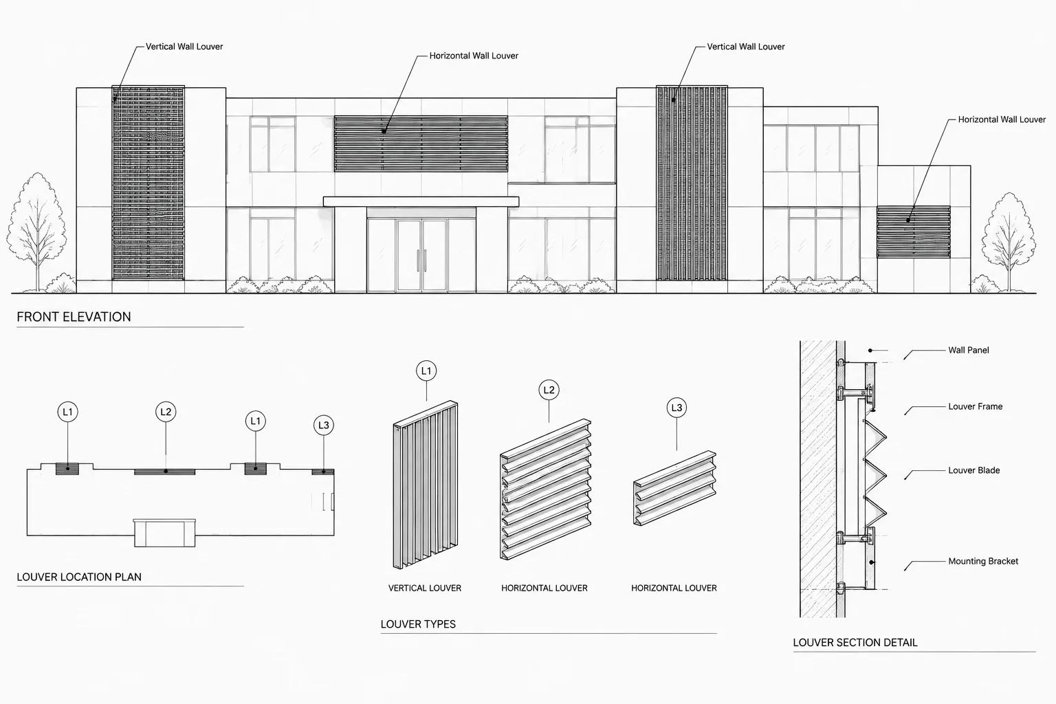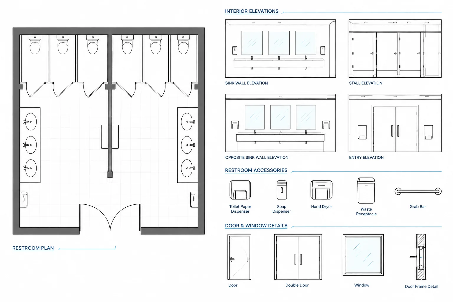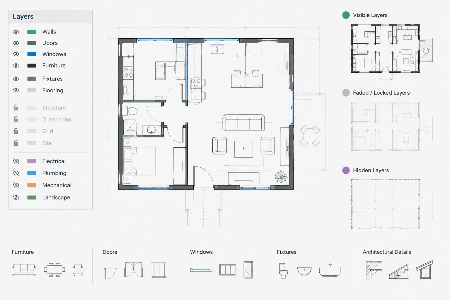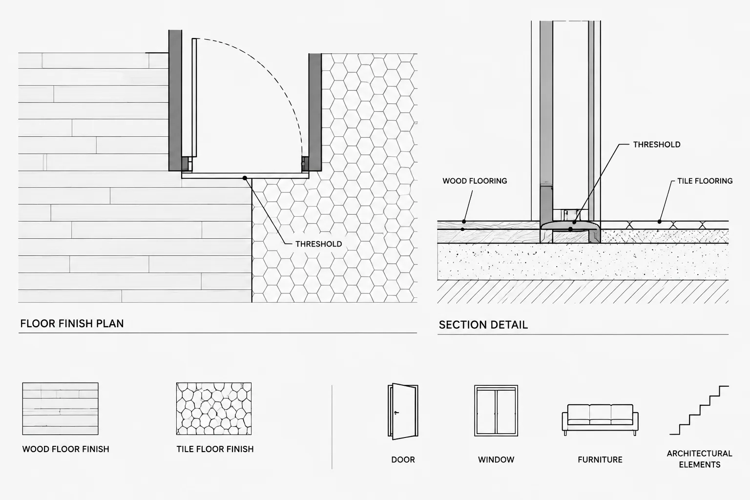
Learning how to dimension an architectural floor plan in CAD is not simply a matter of placing measurements around walls. Effective dimensions identify the controls that organize the design, show how construction elements are located, and remain understandable when the drawing is printed or reviewed outside the CAD environment.
The following guide explains how to select dependable references, organize dimension strings, coordinate openings and wall assemblies, and review the finished plan. The emphasis is on drafting judgment: deciding which relationships need to be communicated, where that information belongs, and how to avoid dimensions that are technically present but difficult to use.
Architectural floor plan dimensions do more than describe size. They communicate design intent, locate construction elements, support coordination, and help reviewers understand how the plan is organized. A drawing can be geometrically accurate yet difficult to use if its dimensions are incomplete, duplicated, poorly grouped, or tied to unreliable reference points.
A dependable dimensioning workflow begins before the first dimension object is placed. The drafter must decide what the plan needs to communicate, which elements control the layout, and where each dimension belongs. The goal is not to label every measurable distance. It is to provide a clear, traceable path from major building controls to the elements that must be located.
Start with the purpose of the plan
Dimensioning should respond to the role of the drawing. A general floor plan, enlarged room plan, partition layout, demolition plan, and finish plan may show the same geometry but require different dimensions.
A general floor plan commonly establishes the overall building form, major wall locations, grids, openings, and important spatial relationships. An enlarged plan can communicate finer layout information that would make the general plan crowded. A demolition plan may locate removal limits from existing construction rather than from proposed partitions.
Before drafting dimensions, identify:
- The elements being constructed or located from the plan
- The base information controlled by another discipline or drawing
- The level of detail appropriate for the sheet scale
- Which dimensions belong on an enlarged plan or detail instead
- Whether existing, proposed, and temporary conditions must be distinguished
This prevents the common mistake of applying the same dimension pattern to every plan type.
Establish reliable dimension references
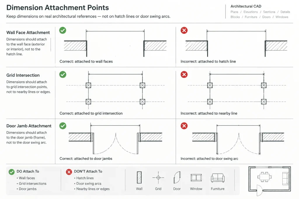
Every dimension should terminate at an intentional reference. Suitable references may include grid lines, wall faces, wall centerlines, structural faces, opening jambs, column centerlines, or another clearly defined control element. The correct choice depends on the project and on what must be located during construction.
Avoid snapping dimensions to incidental graphics such as hatch lines, furniture blocks, masking boundaries, annotation, or an approximate point on a referenced drawing. These objects may move independently, be replaced, or represent something other than the actual construction control.
Be consistent about wall references
Dimensions can become ambiguous when one string references wall faces while another references wall centerlines without a clear reason. Decide how major wall types will be located and apply that method consistently. Where a different reference is necessary, make the intent visually clear or support it with an appropriate note.
Be especially careful with composite walls. A line representing a finish face is not interchangeable with a structural or framing reference. If wall assemblies change later, dimensions attached only to finish graphics may no longer express the intended layout control.
Use grids as primary controls when appropriate
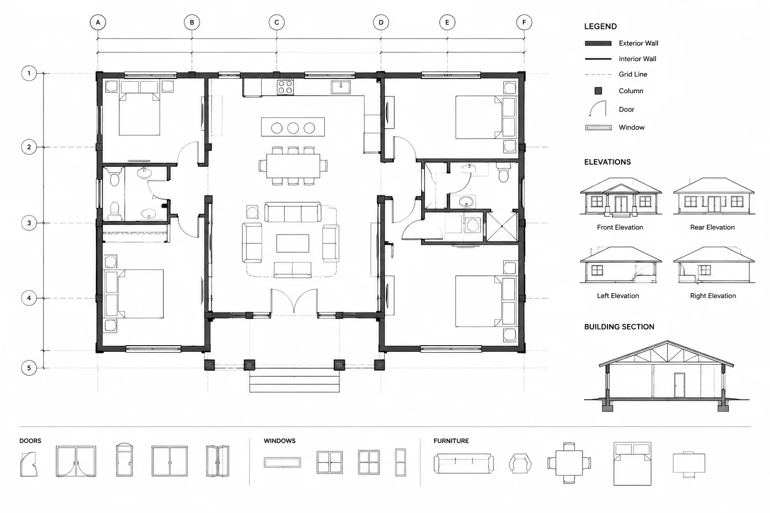
Column grids often provide stable references for structural coordination and major building organization. Architectural dimensions can relate walls, shafts, facade elements, and other features to those grids when the grid is the true controlling system. Do not use a grid merely because it is nearby; confirm that the relationship is intentional and coordinated.
Build dimensions as a hierarchy
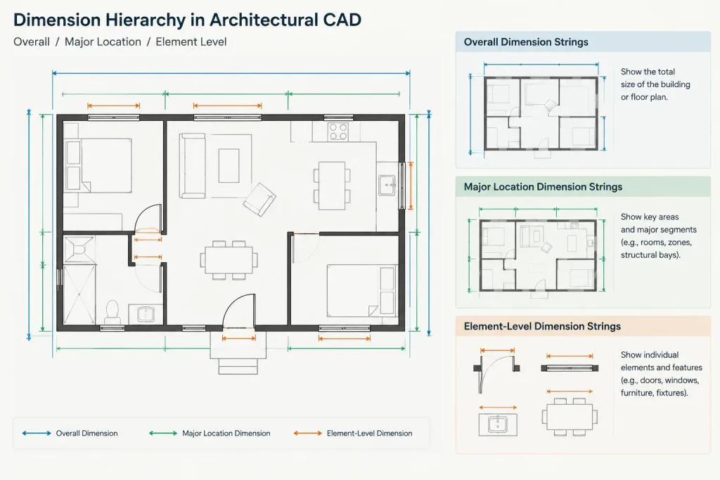
Clear floor plan dimensions usually work as a hierarchy rather than as a collection of isolated measurements. A reader should be able to move from the overall building geometry to major subdivisions and then to individual elements.
| Dimension level | Typical purpose | Common references |
|---|---|---|
| Overall | Defines the total extent of a building wing, facade, or major plan segment | Exterior control faces, grids, or other primary limits |
| Major location | Locates structural bays, major walls, cores, and significant breaks | Grid lines, structural faces, and principal wall references |
| Element location | Positions openings, partitions, recesses, and other individual features | Jambs, wall faces, centerlines, and coordinated control points |
| Room or detail | Communicates localized layout information | Interior wall faces, fixtures, equipment, or detail-specific controls |
Place the most detailed string closest to the plan and progressively broader strings farther away. This creates a predictable reading order and reduces crossed extension lines. The exact arrangement may vary with office standards and drawing conditions, but the hierarchy should remain understandable.
Choose between chained and baseline dimensions
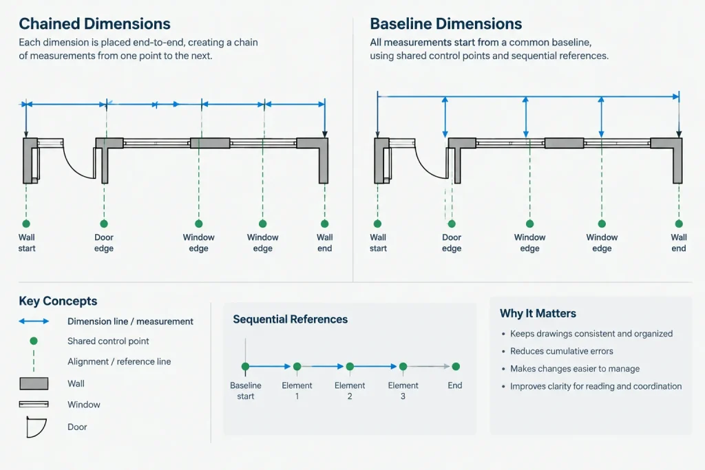
Chained dimensions locate consecutive elements from one another. They are compact and can clearly describe a sequence of adjacent spaces or openings. However, a change to one segment can affect the interpretation of everything that follows.
Baseline dimensions locate multiple elements from a shared control point. They can make critical locations easier to verify because each measurement returns to the same origin. They may require more drawing space and can become visually dense when overused.
Many architectural plans benefit from a combined approach:
- Use overall dimensions to establish the total extent.
- Use major dimensions to locate principal divisions.
- Use chained dimensions where adjacent relationships matter.
- Use baseline dimensions where several critical elements depend on one fixed control.
The selected method should reflect construction intent, not simply the fastest way to place dimension objects.
Dimension doors, windows, and openings deliberately
Openings require a consistent reference convention. A door may be located by its jamb, centerline, rough opening, or relationship to an adjacent wall. A window may be dimensioned to a centerline, masonry opening, frame edge, or grouped facade control. These references are not automatically equivalent.
Coordinate plan dimensions with door and window schedules, type elevations, wall details, and structural openings. If a plan dimension locates a finished frame while another drawing controls a rough opening, the relationship must be intentionally resolved.
Avoid deriving critical opening locations from door swing arcs or symbolic block extents. The swing communicates operation, while the wall opening and jamb geometry should provide the dimensional reference.
Keep dimensions readable
Dimension placement should support the visual hierarchy of the floor plan. Dense strings placed directly over walls, tags, fixtures, and poche can obscure both the geometry and the annotation.
- Keep exterior dimension strings outside the building outline when practical.
- Reserve clear zones around dimension text.
- Avoid running extension lines through room names and tags.
- Do not stack unrelated dimensions merely to fill an available gap.
- Use enlarged plans when localized dimensions cannot remain legible on the general plan.
- Maintain consistent text orientation and spacing across the sheet.
Dimensions should also be visually subordinate to the primary cut geometry. Their plotted weight, text style, arrow or tick style, and extension-line appearance should follow the project dimension style rather than object-level overrides.
Use associative dimensions carefully
Associative dimensions can update when referenced geometry changes, which is valuable during design development. They still require review. A dimension may lose its association, attach to the wrong endpoint, or remain associated with geometry that no longer represents the intended control.
Use accurate object snaps when placing dimensions and inspect attachment points after modifying walls, replacing blocks, editing external references, or changing plan geometry. Do not assume that a displayed value is correct merely because the dimension object appears intact.
Dimensions copied between areas deserve particular attention. The copied object may retain inappropriate references or communicate a relationship that was valid only in the original location.
Avoid redundant and conflicting information
Repeating a dimension can help the reader when a plan is divided across sheets or when an enlarged view must stand on its own. Uncontrolled repetition, however, creates coordination risk. If the same relationship appears in several places, each instance must remain consistent after revisions.
Before adding a dimension, ask whether the information is already controlled by:
- A grid system
- An overall or major dimension string
- An enlarged plan
- A section or detail
- A door, window, or room schedule
- A typical layout note
Reference the more appropriate drawing when possible instead of reproducing detailed information at an unsuitable scale.
Separate verified values from temporary layout information
Design drawings often contain provisional geometry, imported backgrounds, and unresolved field conditions. Do not present an unverified measurement with the same authority as a coordinated project dimension. Temporary dimensions should be placed on controlled working layers or removed before issue.
Existing-condition dimensions require particular caution. Distinguish between values measured in the field, values taken from record drawings, and values inferred from a CAD background. The project team should define how those sources are identified and verified.
Perform a dimension quality-control pass
A useful review is more than checking arithmetic. Trace the plan as if you were trying to lay it out without access to the CAD model.
- Confirm that the overall extent is established.
- Verify that major walls, grids, cores, and plan breaks can be located.
- Check that important openings and recesses have intentional references.
- Look for gaps, duplicated strings, and unexplained changes in reference method.
- Compare dimensions with schedules, enlarged plans, elevations, and sections.
- Inspect extension-line endpoints at high zoom.
- Confirm that no text, tags, or geometry conceal dimension information.
- Review the plotted sheet or PDF, not only the model-space view.
- Remove temporary dimensions and object-level graphic overrides.
It is also useful to compare the sum of chained segments with the related overall dimension. A mismatch may indicate missing segments, rounded display values, incorrect snap points, or geometry that has changed without a complete annotation update.
Make dimensioning part of design coordination
Floor plan dimensioning should not be treated as final decoration added just before issue. Creating dimensions often exposes unresolved wall alignments, inconsistent opening locations, unclear grid relationships, and conflicts between architectural and consultant backgrounds.
Develop dimensions alongside the plan, then review them whenever controlling geometry changes. A successful dimension layout gives the reader enough information to understand and locate the work without forcing them to calculate from incidental geometry. When references, hierarchy, and drawing scale are handled deliberately, architectural floor plan dimensions become a reliable coordination system rather than a collection of measurements.
A practical way to apply the workflow
Before dimensioning, make a brief control map of the plan. Identify the grids, primary wall references, structural elements, major openings, and localized layouts that govern the geometry. This separates true layout controls from lines that merely depict finishes, symbols, furniture, or background information.
Develop the dimensions outward from those controls. Confirm the detailed relationships near the plan, connect them to major locations, and then verify the overall extent. Where a relationship cannot be explained clearly at the plan scale, move the information to an enlarged plan or detail rather than compressing more annotation into the same area.
Review dimensions as instructions, not labels
A strong final check is to ignore the convenience of the editable model and read the plotted drawing as a separate document. Ask whether another person could identify the intended reference for each important location without measuring the drawing or guessing which wall line controls.
If a dimension depends on an unstated assumption, an incidental endpoint, or information shown differently elsewhere, revise the reference or clarify the drawing relationship. This instruction-based review often reveals coordination problems that a simple scan for missing values will not catch.
Protect the dimension system during revisions
When plan geometry changes, review the complete affected dimension hierarchy rather than only the dimension nearest the edit. A shifted wall or opening can alter chained relationships, overall extents, schedule coordination, and dimensions shown on related views.
Treat each issued dimension as part of a connected communication system. Stable references, consistent conventions, and deliberate revision checks make that system easier to maintain throughout design and documentation.
Frequently asked questions
Should every wall on a floor plan be dimensioned?
No. Dimension the walls and other elements that must be located from the drawing. Avoid repeating relationships already controlled clearly by grids, major dimension strings, enlarged plans, details, schedules, or coordinated typical conditions.
Should dimensions reference wall faces or wall centerlines?
The appropriate reference depends on what controls the construction. A finish face, structural face, framing reference, and wall centerline can represent different intents. Choose the relevant control and use it consistently rather than switching references for graphic convenience.
How should door and window locations be dimensioned?
Use an intentional opening reference, such as a jamb, centerline, frame edge, or coordinated opening control. Confirm that the selected reference agrees with the related schedule, elevation, wall detail, and structural information. Do not use a door swing arc as the location control.
When should baseline dimensions be used instead of chained dimensions?
Baseline dimensions are useful when several important elements must relate to one stable origin. Chained dimensions are useful when the sequence of adjacent relationships matters. A plan may use both methods, provided their purposes and reference points remain clear.
Why can an associative CAD dimension still be wrong?
Association indicates a connection to geometry, but it does not prove that the geometry is the correct construction control. A dimension can attach to an unintended endpoint, retain an unsuitable copied reference, or follow an object that no longer represents the design intent.
How should dimension conflicts be resolved?
Trace each conflicting value back to its controlling geometry and related documentation. Check grids, wall references, openings, enlarged plans, schedules, sections, and consultant information. Do not resolve the conflict by changing only the displayed text or hiding one of the dimensions.
What should be checked before issuing a dimensioned floor plan?
Review reference points, overall and major controls, opening locations, duplicated information, related views, temporary dimensions, annotation clearance, and the plotted output. Changes to controlling geometry should trigger a review of every affected dimension relationship.