Object snaps are essential to accurate CAD work, but precision depends on more than seeing a snap marker. The selected point must belong to the correct wall, opening, grid, block, reference, or detail component. In a crowded architectural drawing, a geometrically valid snap can still produce the wrong design relationship.
This guide explains how to use object snaps in AutoCAD with greater control, how to distinguish running snaps from temporary overrides and tracking, and how to diagnose gaps, false intersections, elevation conflicts, and unexpected snap locations.
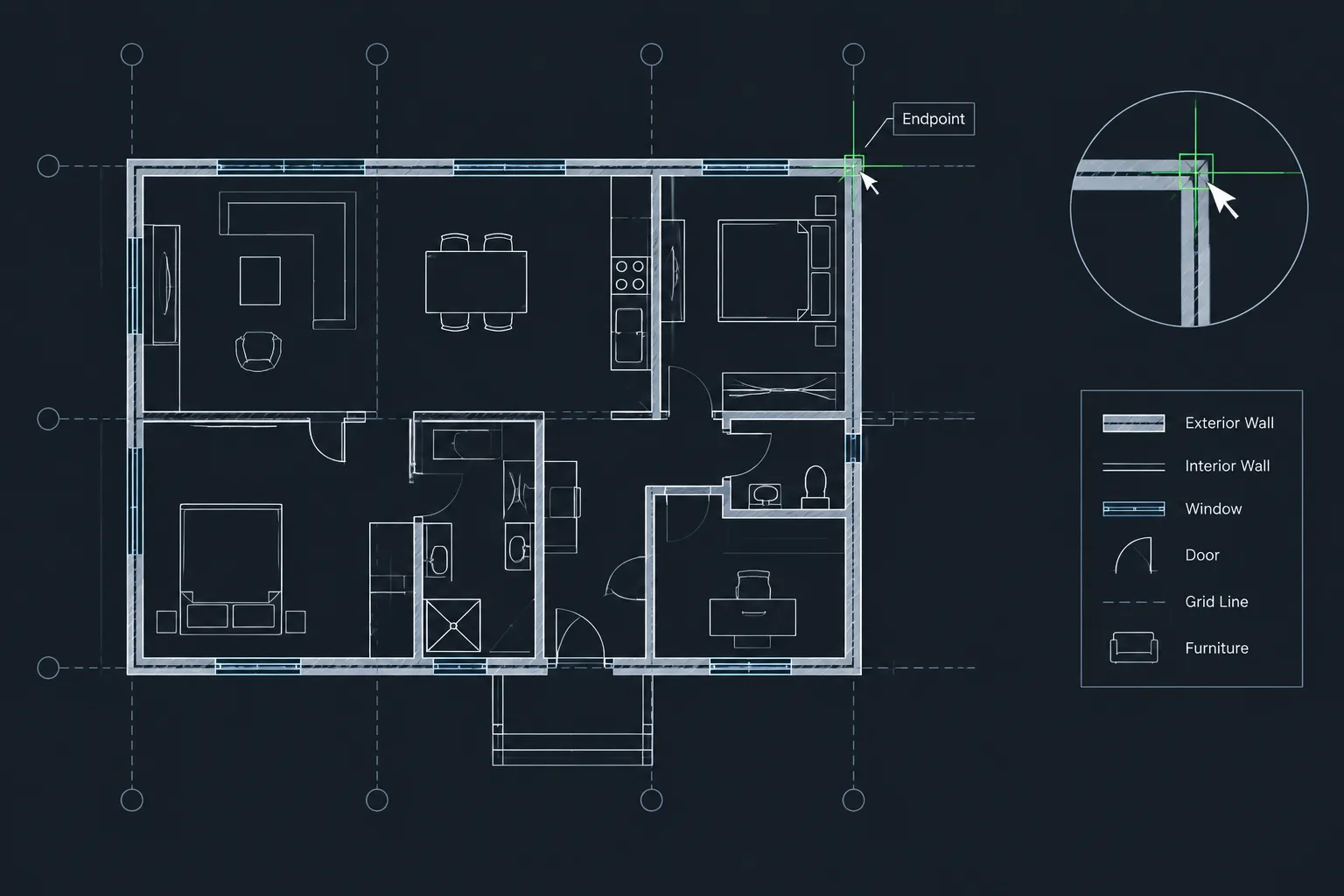
Accurate architectural CAD geometry depends on selecting the intended geometric point rather than clicking approximately. AutoCAD object snaps help locate endpoints, intersections, centers, perpendicular points, and other precise positions on drawing objects. Used carefully, they support clean wall connections, aligned openings, dependable dimensions, and coordinated references. Used without visual confirmation, they can just as easily create tiny gaps, unintended offsets, or connections to the wrong object.
The goal is not to activate every available snap mode. A reliable workflow uses a restrained set of running object snaps, temporary overrides for special conditions, and a deliberate check before each critical point is accepted.
What an object snap actually controls
An object snap identifies a geometric point during a drawing or editing command. It does not repair the source geometry, force objects onto the same elevation, or guarantee that the selected point belongs to the intended architectural element. If several eligible points are close to the cursor, AutoCAD may offer a valid snap that is still wrong for the task.
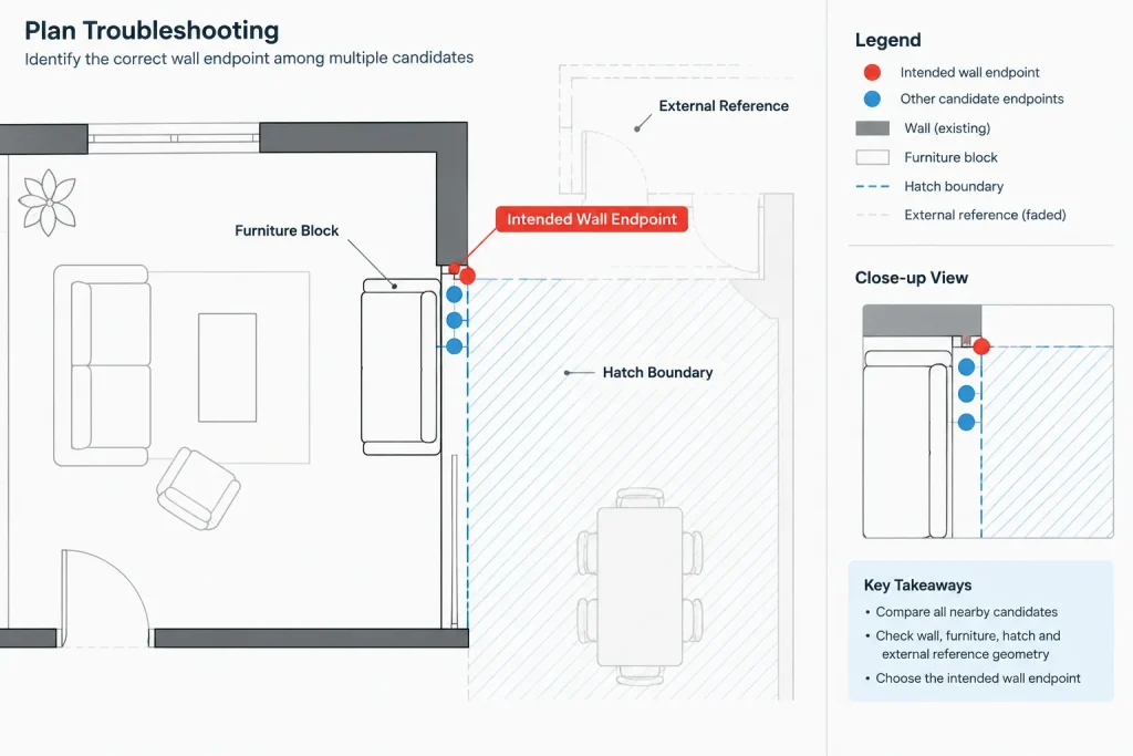
For example, a wall line, furniture block, hatch boundary, and xref line may occupy the same small screen area. An endpoint marker confirms that an endpoint was found, but the drafter must still confirm which object owns that endpoint.
Useful snap modes for architectural work
| Snap mode | Typical architectural use | Main caution |
|---|---|---|
| Endpoint | Connecting wall lines, trim edges, section markers, and detail components | Nearby short segments or block geometry may provide an unintended endpoint |
| Midpoint | Centering an opening, symbol, fixture, or annotation between known limits | The midpoint of a drawn line is not automatically the center of the built assembly |
| Intersection | Locating crossing grids, wall faces, reference lines, and detail geometry | The objects must have a suitable geometric relationship; elevation differences can complicate the result |
| Extension | Projecting alignment from an existing edge without adding permanent construction geometry | It is easy to track from the wrong source when the drawing is crowded |
| Perpendicular | Drawing a return, offset connection, or reference line square to an existing object | Confirm that the source edge represents the intended alignment |
| Center | Finding the center of circles and arcs used for columns, openings, or curved elements | Imported curves may not be true circles or arcs |
| Quadrant | Connecting geometry to cardinal points on circles and arcs | The selected quadrant may not match the design axis or view orientation |
| Nearest | Placing a point somewhere along an object when no defined geometric location is required | It can produce arbitrary locations and should not replace endpoint or intersection snaps |
Additional snap modes may be useful for specialized geometry, but keeping all modes active continuously can make point selection harder. A limited running set is usually easier to read and control.
Build a restrained running object snap setup
Running object snaps remain available while commands request points. For common architectural drafting, endpoint, midpoint, intersection, and center are often a practical starting group. The exact selection should reflect the geometry being produced rather than a universal office preset.
Add other modes temporarily when a task requires them. A one-time object snap override lets the drafter request a specific snap for the next point without permanently expanding the running set. This is particularly useful for perpendicular, tangent, quadrant, or nearest selections.
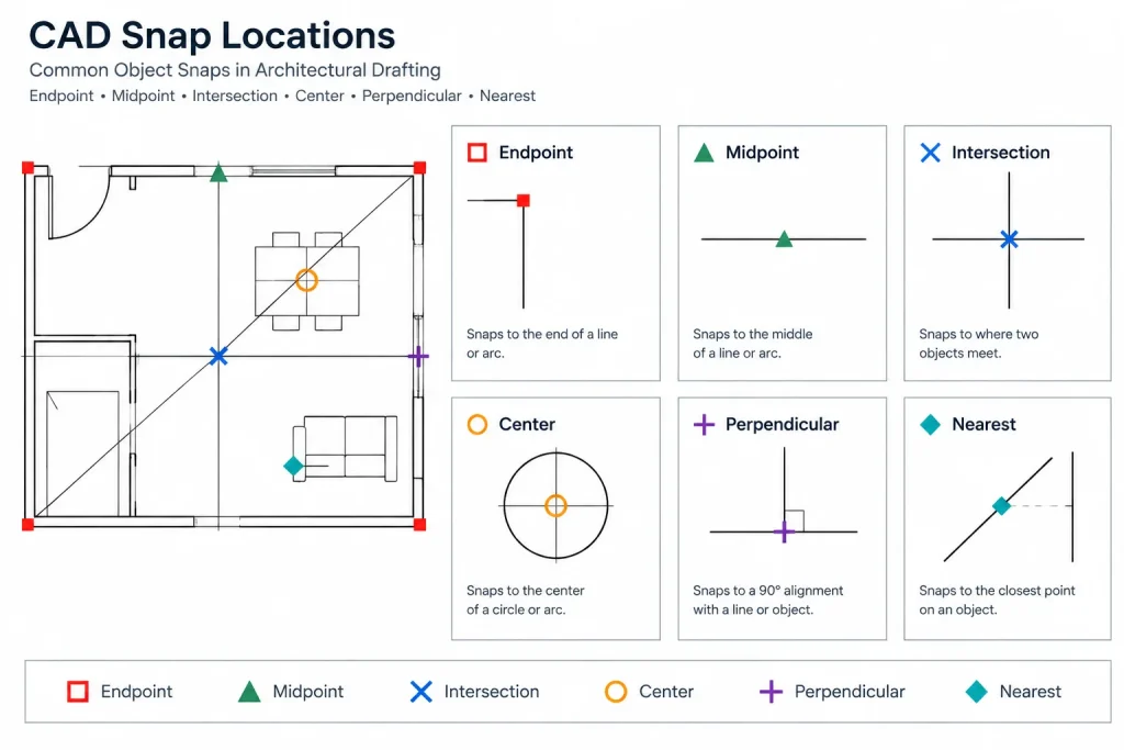
When several snap candidates appear close together, pause before clicking. Move the cursor slightly, inspect the marker and tooltip, and cycle through available candidates when necessary. Zooming in can help, but magnification alone does not identify the correct source object.
A reliable point-selection workflow
1. Identify the architectural relationship first
Decide what the new point represents before selecting it. Is it the face of finish, centerline of a partition, edge of an opening, structural grid intersection, or endpoint of a reference line? This prevents the software from defining the relationship merely because a snap marker appeared.
2. Reduce visual competition
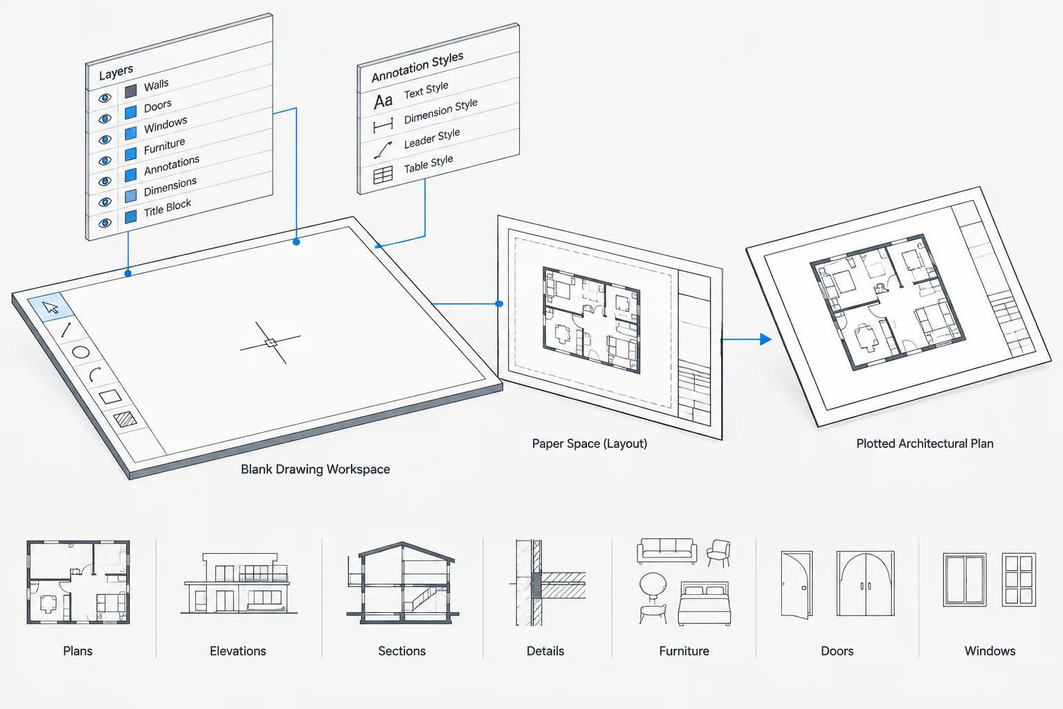
Freeze, hide, lock, or isolate unrelated layers when practical. If furniture, ceiling geometry, demolition work, and backgrounds overlap the active plan, there may be many valid but irrelevant snap points. Layer control improves selection clarity without changing the geometry.
3. Start the command, then acquire the point
Object snaps operate when AutoCAD is asking for a point. Begin the drawing, move, copy, rotate, dimension, or editing command, then approach the intended object. Avoid rapid clicking based only on cursor position.
4. Confirm the marker and source object
Check both the snap type and the highlighted geometry. An endpoint marker on a furniture block is not a substitute for the endpoint of a wall. If the source is ambiguous, cancel or move away and reacquire the point.
5. Verify the result after placement
Inspect the completed connection. Use grips, object properties, distance checks, or temporary construction geometry to verify important alignments. Critical geometry should not be accepted solely because it looks connected at the current zoom level.
Object snap tracking versus permanent construction lines
Object snap tracking can project alignment paths from acquired snap points. It is useful for locating a new point horizontally, vertically, or along configured tracking directions without drawing extra lines. This can keep a plan cleaner and reduce temporary geometry.
Tracking is most dependable when the drafter acquires only the intended source points and watches the displayed alignment path. In dense files, several acquired points can create competing paths. Move away, clear the acquisition, or restart the point selection if the tracking display becomes ambiguous.
Permanent or temporary construction lines are still valuable when an alignment must be reviewed by others, reused repeatedly, or coordinated across several elements. Tracking is a placement aid; it is not documentation of design intent.
Common object snap failures and how to diagnose them
The cursor snaps to the wrong object
Overlapping geometry, dense blocks, hatch boundaries, and xrefs are common causes. Isolate relevant layers, lock references that should not be edited, or use a specific snap override. Confirm the highlighted source before accepting the point.
Lines look connected but contain a small gap
This often results from clicking near an endpoint with object snaps disabled, choosing nearest instead of endpoint, or snapping to adjacent geometry. Inspect the area closely and compare endpoint coordinates or grips. Correct the geometry rather than masking the gap with heavier linework.
An expected intersection cannot be found
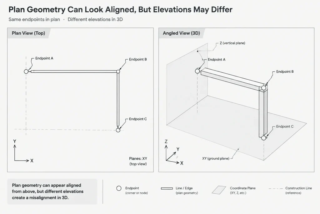
The objects may stop short, cross only visually, or sit at different elevations. Check their properties and inspect the geometry from another view when elevation is suspected. Do not assume that a plan-view crossing is a true geometric intersection.
Snaps appear away from visible linework
Potential causes include objects with nonzero elevation, distant block components, invisible or clipped reference geometry, and complex objects whose defining geometry differs from their displayed appearance. Review object properties and the source file before moving geometry arbitrarily.
Imported drawings produce inconsistent snap behavior
PDF conversions, survey exports, consultant files, and legacy details may contain fragmented polylines, duplicate objects, splines, or geometry at inconsistent elevations. Treat these files as references until their structure has been reviewed. Redrawing a controlled architectural edge may be safer than relying on irregular imported segments.
Snapping to blocks and external references
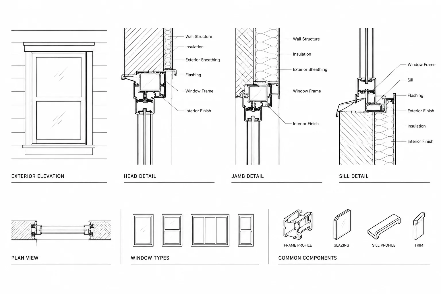
Blocks can contain many internal endpoints, insertion-related geometry, attributes, and nested objects. Before using a block as a dimensional or alignment reference, determine which component represents the actual architectural control point. The visible outline of a symbol may be diagrammatic rather than a construction edge.
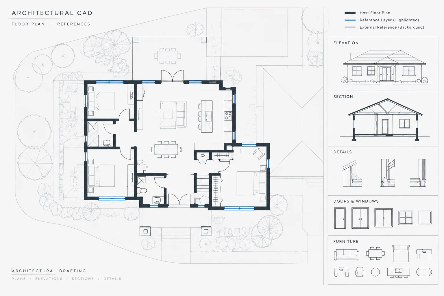
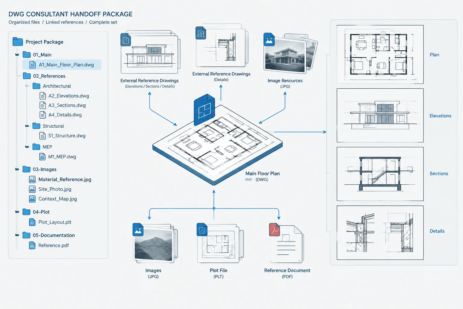
External references are useful coordination backgrounds, but their geometry may change when the source file is updated. If active design geometry depends on an xref location, document the relationship and recheck it after background updates. Avoid casually modifying host geometry to follow an unexplained shift in a reference file.
Two-dimensional drawings and elevation problems
A floor plan can appear flat while some objects carry different elevation values. Object snaps may then capture points that align on screen but do not share the same coordinate plane. Symptoms include failed joins, unreliable intersections, unexpected measurements, or geometry that appears displaced in another view.
Check object properties when these symptoms occur. Correct elevation only after determining whether the drawing is intended to be strictly two-dimensional or whether the height information is meaningful. Flattening an entire file without review can damage useful geometry.
Quality-control checklist
- Keep the running object snap set limited to frequently needed modes.
- Use temporary overrides for specialized point selections.
- Confirm the snap marker, tooltip, and source object before clicking.
- Avoid nearest when a defined geometric relationship is required.
- Reduce overlapping layers and references during precise editing.
- Check object elevations when intersections or joins behave unexpectedly.
- Verify important connections with grips, properties, or measurement tools.
- Recheck geometry tied to updated external references.
- Do not assume a block outline represents a verified construction dimension.
- Inspect imported geometry before using it as a control reference.
Precision is a drafting decision
Object snaps provide access to exact geometric points, but they cannot determine architectural intent. Reliable drafting combines the correct snap mode with clear layer control, deliberate source selection, and post-placement verification. That discipline produces cleaner wall intersections, better coordinated openings, more dependable dimensions, and DWG files that are easier for the next person to understand and edit.
Choosing snaps according to design intent
A useful way to evaluate any snap selection is to separate geometric accuracy from architectural intent. Geometric accuracy means the cursor found a defined point on an object. Architectural intent means that point represents the correct control relationship for the drawing.
For example, a midpoint may be mathematically correct while failing to represent the center of a finished assembly. An intersection may be visible in plan while the objects remain separated by elevation. An endpoint inside a block may belong to symbolic graphics rather than the construction edge being coordinated.
Use a hierarchy of evidence
- First, identify the relationship: decide whether the point should reference a face, centerline, grid, opening edge, or another architectural control.
- Then, identify the object: confirm that the highlighted geometry belongs to the intended element or reference.
- Finally, confirm the snap type: verify that the marker represents the required endpoint, midpoint, intersection, center, or other geometric condition.
This order prevents a visible marker from becoming the sole reason for accepting a point. It also makes troubleshooting faster because the drafter can determine whether the problem comes from the selected object, the snap mode, the source geometry, or its coordinate position.
When to stop and inspect the drawing
Repeated snap failures often indicate a geometry or file-organization problem rather than a cursor-setting problem. If expected points remain unavailable, inspect object properties, block contents, overlapping layers, external references, and imported linework before continuing. Repairing or replacing an unreliable control edge is generally clearer than building additional work around unexplained geometry.
Frequently asked questions about AutoCAD object snaps
Why does AutoCAD snap to the wrong endpoint?
Several objects may have eligible endpoints within the cursor area. Blocks, reference files, hatch boundaries, furniture, and short line segments can compete with the intended architectural edge. Reduce visual competition, use a temporary snap override, and confirm which object is highlighted before accepting the point.
Why do two lines look connected but fail to join?
The lines may contain a small gap, overlap without sharing an endpoint, or exist at different elevations. Inspect their grips and properties rather than relying on the current display scale. Correct the underlying geometry after identifying the cause.
Should every object snap mode remain active?
No. A large running set can create too many candidates in a dense drawing. Keep frequently used modes available and call specialized modes temporarily when the current task requires them.
What is the difference between object snaps and object snap tracking?
An object snap locates a defined point on geometry. Object snap tracking projects an alignment path from an acquired point so another point can be placed in relation to it. Tracking assists placement but does not create a permanent reference showing design intent.
Why is a visible crossing not recognized as an intersection?
The objects may stop short, cross only because of the viewing direction, or carry different elevation values. Review their geometry and properties, and inspect another view if the drawing may contain nonplanar objects.
Can blocks and external references be trusted as snap references?
They can provide useful reference points, but the selected component must represent the intended architectural control. Block graphics may be symbolic, while external-reference geometry can move when its source is updated. Important dependent geometry should be reviewed whenever the reference changes.
Why do imported files behave inconsistently with object snaps?
Converted and consultant-supplied drawings may contain fragmented segments, duplicate objects, splines, nested content, or inconsistent elevations. Review the file structure before treating imported geometry as a reliable control reference.