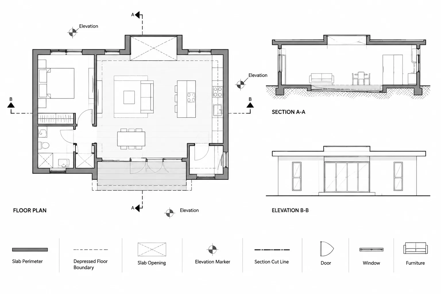
Drafting slab edges in architectural CAD requires more than tracing a structural background. Each line must communicate whether it represents a slab perimeter, lowered area, step, recess, opening, finish transition, or raised element. Clear classification prevents similar-looking boundaries from carrying conflicting meanings.
This guide explains how to organize slab-related linework, establish controlling references, coordinate plan geometry with sections and details, and review architectural information against structural drawings. The goal is a readable drawing set that communicates design intent while keeping unverified engineering decisions visible as coordination items.
Slab edges, depressions, recesses, and steps can be easy to overlook because they often sit between architectural, structural, waterproofing, and finish-floor information. A line that appears minor on a floor plan may represent a change in structural elevation, a finish transition, a curb, or simply the boundary of a floor material. If these conditions are not distinguished clearly, consultants and builders may interpret the same CAD line in different ways.
A reliable workflow begins by defining what each boundary represents, identifying who controls its location, and coordinating it across plans, sections, details, and consultant backgrounds. The architectural drawing should communicate design intent without implying that unverified structural geometry has been finalized.
Understand the Conditions Before Drawing Them
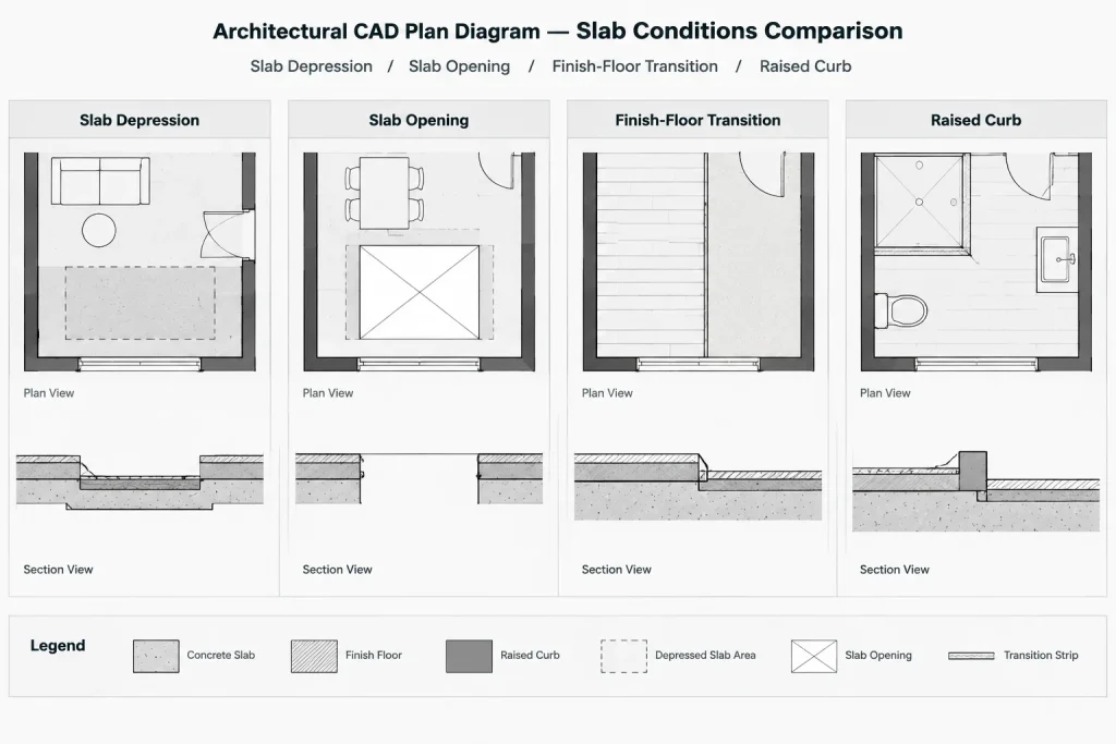
Do not treat every floor-related line as a slab edge. Several conditions can overlap in the same area:
- Perimeter slab edge: The outside boundary of a structural floor slab.
- Slab depression: An area where the structural slab is lowered relative to adjacent construction.
- Slab step: A defined change between structural slab elevations.
- Recess or blockout: A localized area reserved for equipment, a system component, or another coordinated purpose.
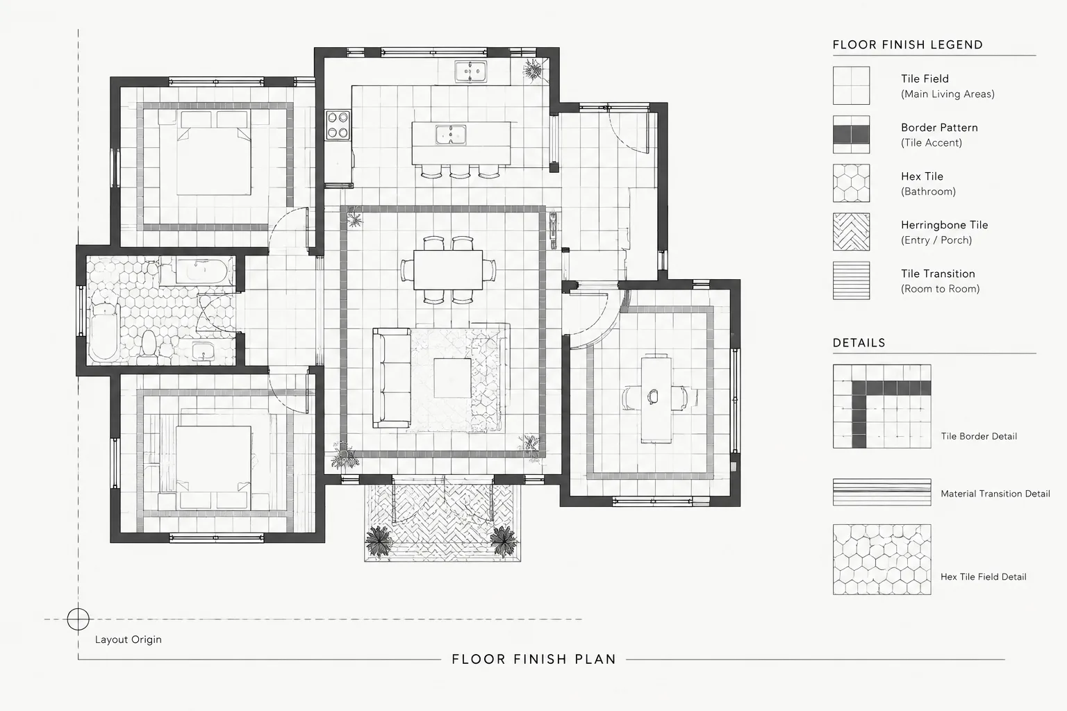
- Finish-floor transition: A change in flooring material or finish elevation that may not require a change in the structural slab.
- Curb or housekeeping pad: A raised element located above the primary slab rather than a change in the slab itself.
- Opening: An area where the slab is absent, usually coordinated separately from a depression.
These conditions may share an outline, but they should not automatically share a layer, linetype, note, or detail reference. Before drafting, determine whether the line describes structural geometry, finish construction, or an annotation boundary.
Establish the Controlling References
Begin with the current architectural floor plan and the latest available structural background. Also review relevant room layouts, equipment plans, plumbing information, sections, and finish documentation. A depression may originate from an architectural requirement, but its depth, reinforcing implications, and final structural configuration typically require engineering coordination.
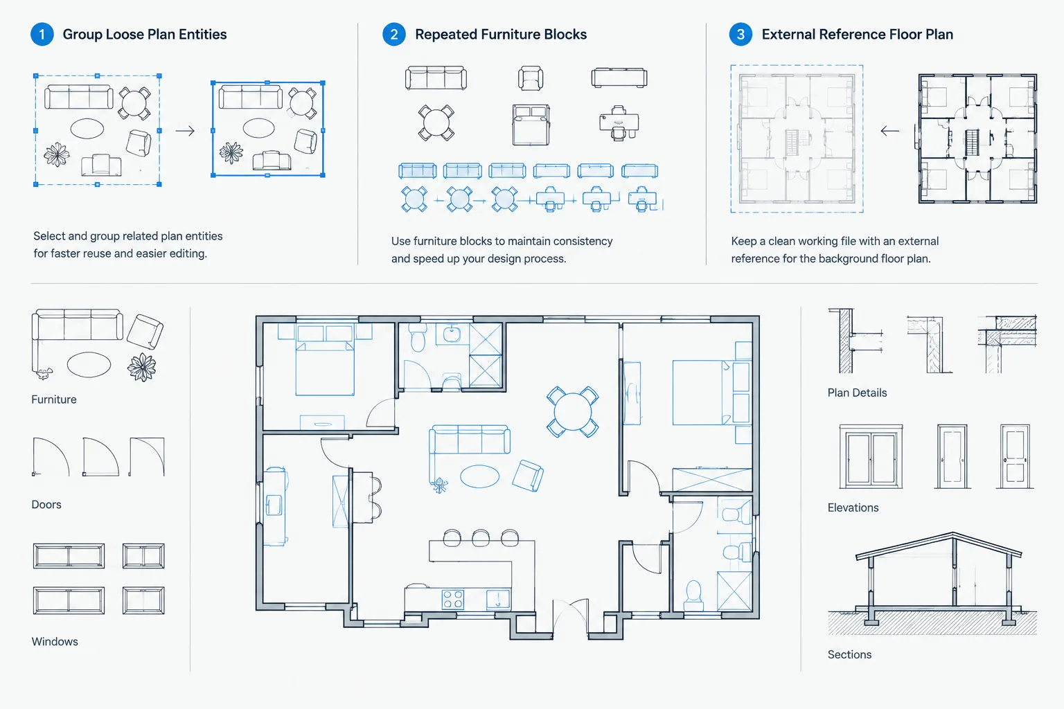
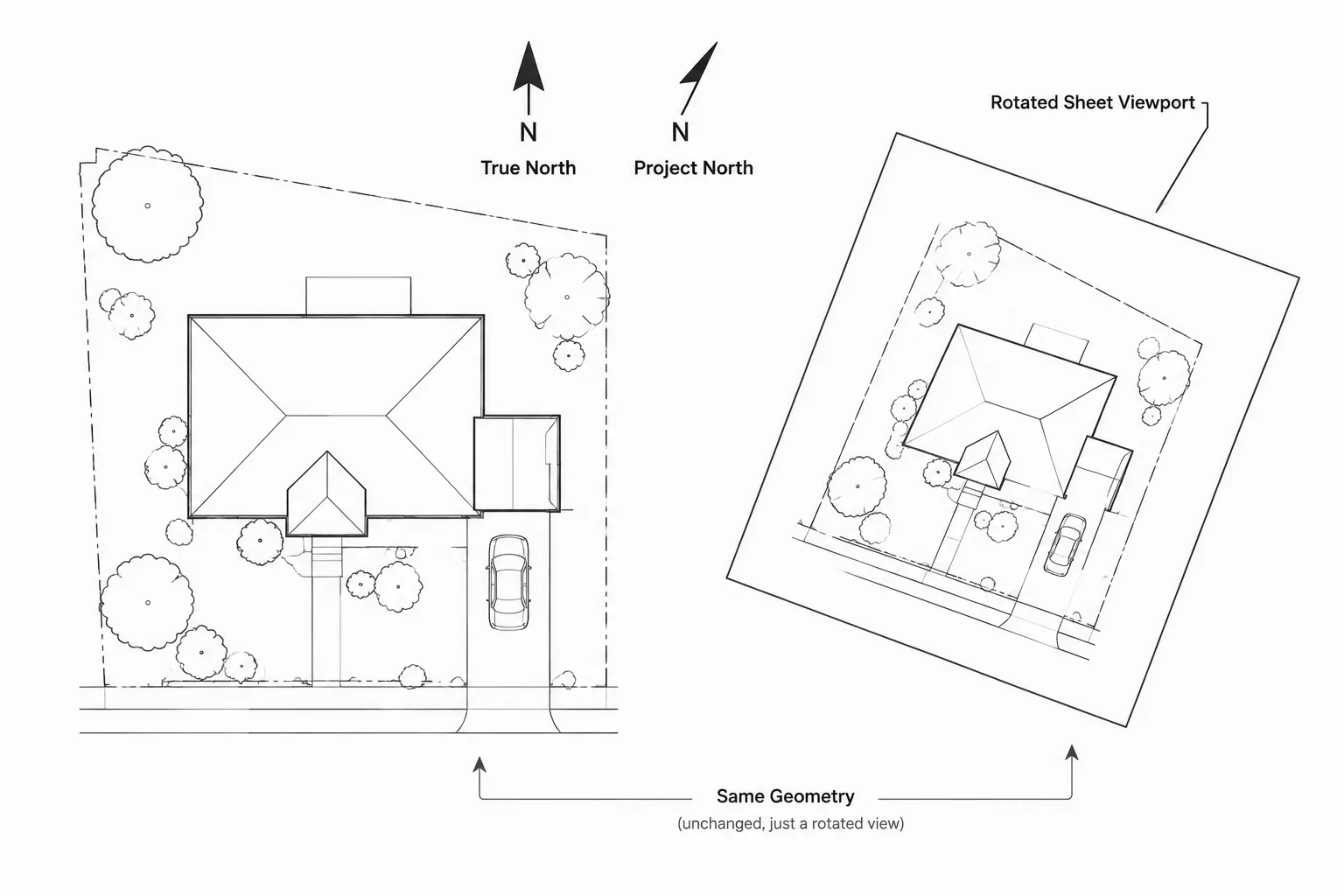
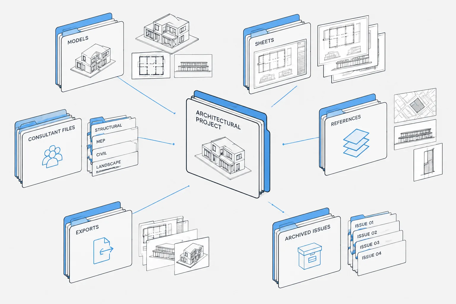
Use a consistent project origin and keep consultant files attached as external references when possible. Avoid copying structural lines into the architectural model without a clear reason. Copied geometry can become outdated while continuing to look authoritative.
For each condition, ask:
- Is the location controlled by a wall face, grid line, equipment footprint, room boundary, or exterior envelope?
- Does the boundary align with structural framing?
- Is the condition required for drainage, waterproofing, finishes, accessibility, or equipment installation?
- Which discipline is responsible for confirming the depth and construction?
- Where will the condition be explained most clearly: plan, section, enlarged plan, or detail?
Build a Clear CAD Layer Strategy
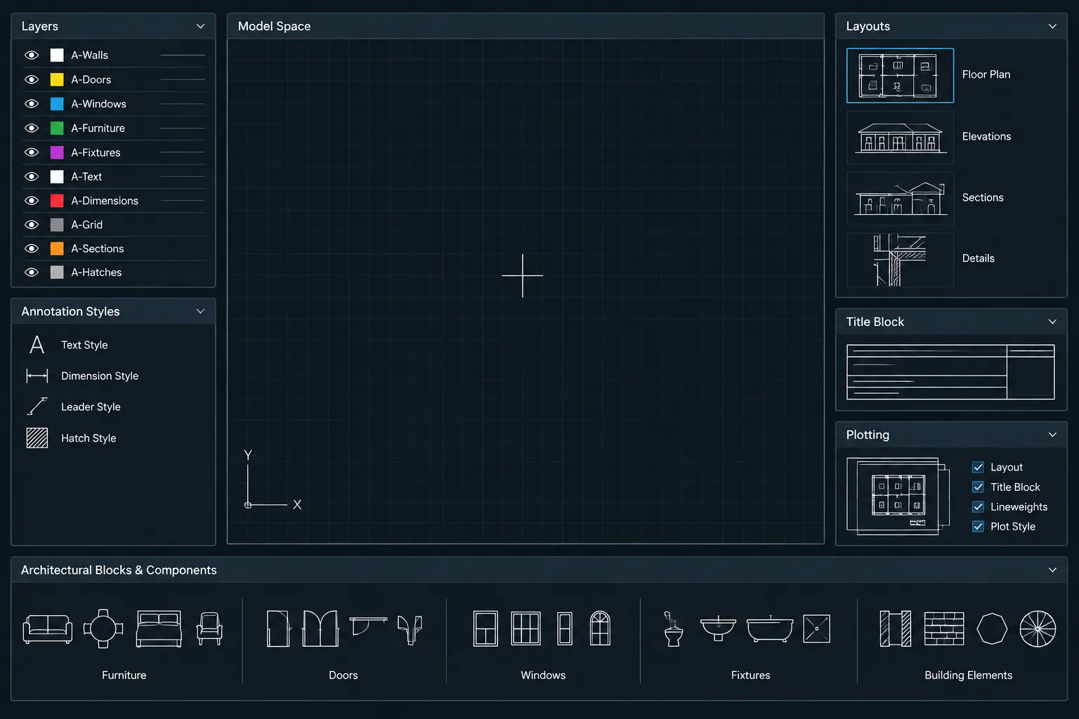
Slab-related graphics should be separable from walls, finish patterns, equipment, and general notes. The exact layer names should follow the project standard, but the organizational logic should remain clear.
| Graphic content | Recommended separation | Coordination purpose |
|---|---|---|
| Primary slab edge | Dedicated architectural slab-edge layer | Shows the intended floor boundary and supports comparison with structure |
| Depression or step boundary | Separate floor-modification layer | Allows distinct display, checking, and revision |
| Slab openings | Opening or penetration layer | Prevents openings from being confused with lowered areas |
| Finish transitions | Finish-plan layer | Keeps finish information independent from structural geometry |
| Notes and elevation markers | Annotation layers | Supports viewport control and readable plotting |
| Structural reference geometry | External reference or reference-only layer | Identifies consultant information without presenting it as architectural linework |
Use object properties consistently rather than forcing individual colors, linetypes, or lineweights. A separate layer for depressions also makes it easier to isolate them during quality-control reviews.
Draft the Plan Geometry
Draw a closed, clean boundary
Represent a depression or recess with a continuous boundary wherever the condition can be understood in plan. Closed polylines are useful because they are easier to select, compare, hatch, and revise than disconnected line segments. Remove duplicate lines and tiny gaps that could interfere with hatching or area checks.
Do not offset the boundary casually from a wall or fixture. Confirm whether the slab condition follows the finished face, rough opening, framing face, equipment clearance, or another control point. The correct reference may change from one condition to another.
Differentiate visible and concealed edges
A slab boundary visible in the plan cut may require a different graphic treatment from a change concealed below flooring or construction. Use the project’s established linetype hierarchy. Avoid adding dashed lines merely because a condition is below the finish surface; the resulting graphic must remain meaningful in the context of that specific drawing.
Limit hatching to useful information
A light hatch can help identify a depressed area on a coordination plan, but it should not compete with walls, fixtures, room tags, or dimensions. If the floor plan is already visually dense, use a boundary, concise note, and detail reference instead. Decorative or overly dark patterns can obscure the exact edge that needs coordination.
Annotate What the Line Means
A boundary without a label can be mistaken for a finish transition, overhead element, or equipment footprint. Add a concise description that identifies the condition. Depending on project practice, the annotation may include a slab designation, a reference elevation, a depth controlled elsewhere, or a direction to a section or detail.
Keep structural slab elevations distinct from finished-floor elevations. If both are shown, label them so the reader does not have to infer which surface is being referenced. Do not calculate or assign a depression depth solely from a finish thickness unless the complete assembly has been verified.
Place notes where leaders do not cross door swings, fixtures, dimensions, or other important information. For repeated conditions, a keyed note or type designation may be clearer than repeating a long description throughout the plan.
Coordinate Plans, Sections, and Details
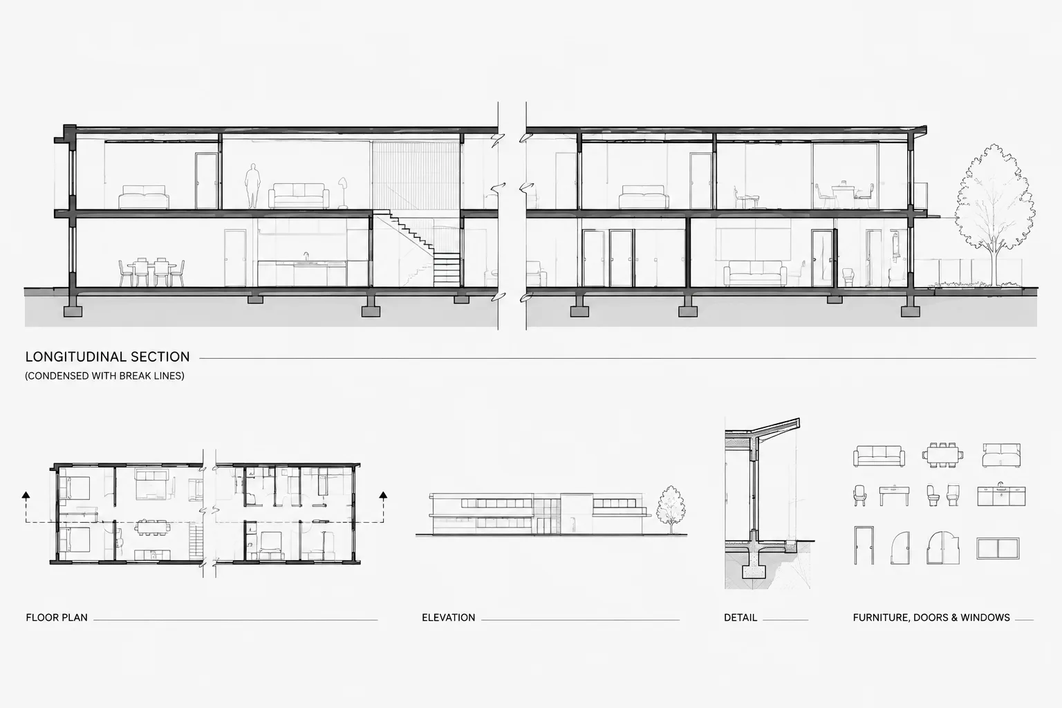
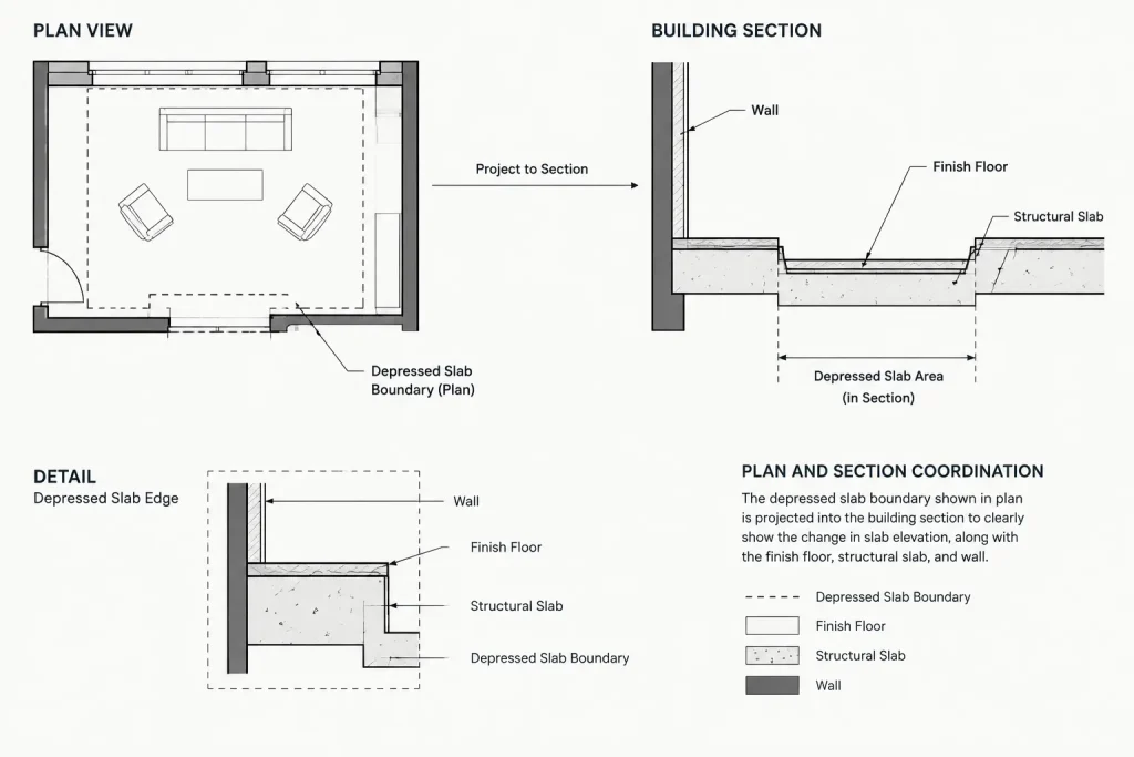
A plan can establish the horizontal extent of a slab condition, but it rarely explains the complete vertical relationship. Add or verify a section where the drawing needs to communicate:
- The relationship between structural slab and finished floor
- The location of waterproofing or floor assembly transitions
- The interface with walls, curbs, doors, or exterior construction
- The difference between a depression, recess, opening, and raised element
- The continuation or termination of the condition at adjacent spaces
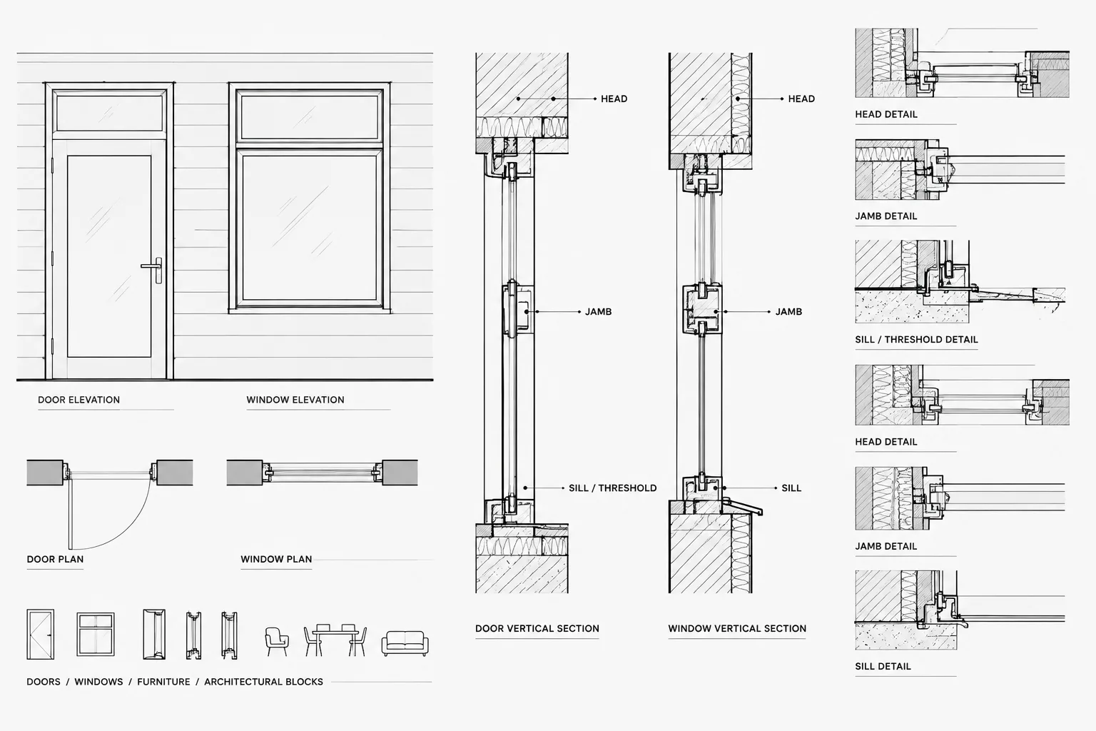
Project the plan geometry into the section rather than redrawing the condition from memory. Check that the section cut actually passes through the relevant edge. A section symbol placed nearby but missing the condition can create false confidence.
If a detail is referenced, confirm that its orientation and construction match the plan. A generic slab-step detail may not explain a perimeter edge, wet-area depression, equipment recess, or exterior threshold equally well.
Compare the Architectural and Structural Drawings
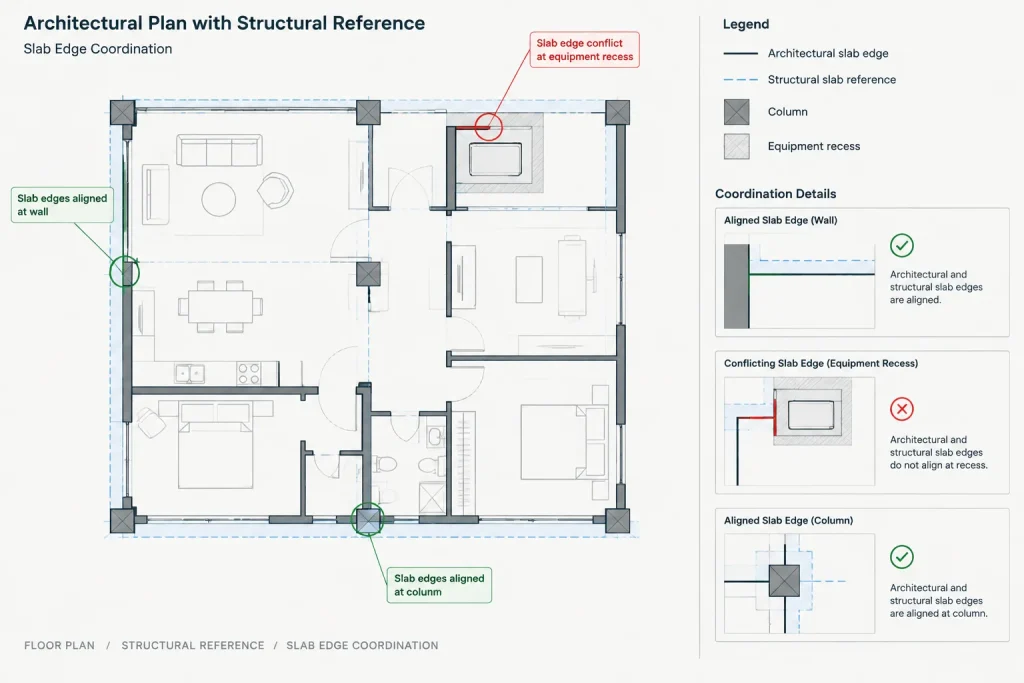
Overlay or visually compare the architectural floor-modification geometry with the structural slab plan. Review the perimeter, each step, every depression, and all nearby openings. Differences should be resolved deliberately rather than hidden by turning off a reference layer.
Common coordination conflicts include:
- A depression boundary crossing a beam, column, bearing wall, or slab opening
- A structural edge that does not align with the intended exterior wall assembly
- A finish transition drafted as though it were a structural step
- A floor drain or plumbing fixture located outside the coordinated depressed area
- A door threshold occurring at an unresolved elevation change
- An equipment recess based on an outdated block or footprint
- A plan note that disagrees with the section or structural reference
When the design is still developing, identify the condition as requiring coordination rather than presenting an assumed solution as final. Track unresolved items in the project’s issue log or coordination notes.
Use a Focused Quality-Control Pass
Before issuing drawings, isolate the slab-edge and floor-modification layers and review them as a system. Then restore the full drawing and check their readability in context.
- Confirm that every boundary has a defined meaning.
- Check that closed areas do not contain gaps, overlaps, or duplicate objects.
- Verify alignment with grids, walls, equipment, and room boundaries.
- Separate slab depressions from openings and finish transitions.
- Compare architectural geometry with the latest structural background.
- Check elevation labels against sections and details.
- Review referenced callouts and confirm that they show the intended condition.
- Plot at the intended sheet scale to test linetypes, hatches, notes, and lineweights.
- Confirm that hidden consultant layers are not carrying unresolved information.
Create a Reusable Coordination Method
The most effective workflow is not a special symbol or a complex CAD object. It is a repeatable process: classify the condition, establish its controlling references, draft clean geometry, label its meaning, coordinate the vertical relationship, compare it with structural information, and perform a dedicated review.
This approach keeps slab-related graphics from becoming ambiguous background lines. It also helps the architectural plan serve its proper role: communicating spatial and construction intent while making responsibility and unresolved coordination visible.
Read the Drawing as a Construction Relationship
During the final review, read each slab-related condition from the perspective of someone who does not know the drafting history. The graphics should answer what changes, where the change begins and ends, which elevation is being referenced, and where the vertical construction is explained.
Test the drawing with surrounding information visible. A boundary that appears clear when isolated may become ambiguous beside flooring patterns, equipment outlines, door swings, plumbing fixtures, or consultant linework. If its meaning depends on layer color alone, strengthen the communication with an appropriate note, graphic distinction, elevation marker, or detail reference.
Manage Revisions Without Losing Coordination
Slab conditions often change when room layouts, equipment, exterior walls, drainage concepts, or structural framing are revised. Update the controlling geometry first, then review every dependent annotation, hatch, section, detail callout, and consultant comparison. Moving only the visible boundary can leave outdated notes or sections elsewhere in the set.
Where responsibility is unresolved, avoid converting an assumption into apparently final construction geometry. Record the issue, identify the affected drawings, and keep the architectural intent distinguishable from consultant reference information. This makes later coordination easier and reduces the chance that obsolete linework will be treated as approved geometry.
Final Communication Test
- Can a reader distinguish a lowered slab from an opening or finish transition?
- Does the plan identify the full horizontal extent of the condition?
- Does a section or detail explain the vertical relationship where needed?
- Are structural and finished-floor references clearly differentiated?
- Do architectural and structural backgrounds show compatible locations?
- Are unresolved conditions identified rather than concealed?
Frequently Asked Questions
What is the difference between a slab depression and a slab opening?
A slab depression is a lowered portion of the slab, while an opening is an area where the slab is absent. They should use distinct graphics and annotations because they communicate different construction conditions.
Should a finish-floor transition be drawn as a slab step?
Not automatically. A finish change may occur without a change in structural elevation. Confirm the complete floor assembly and the intended structural condition before showing a slab step.
Why use a closed polyline for a depression boundary?
A closed polyline is easier to select, revise, compare, and hatch than disconnected segments. It also helps reveal gaps or overlaps during drawing review.
Should structural slab lines be copied into the architectural file?
Consultant geometry is generally clearer when maintained as reference information rather than copied without a specific purpose. Copied lines can remain in the architectural file after the structural background changes and may appear more authoritative than they are.
When does a slab condition need a section or detail?
Add or verify a section or detail when the plan cannot adequately explain the vertical relationship, floor assembly, waterproofing transition, adjacent wall or curb, threshold, or termination of the condition.
How should an unresolved slab depression be documented?
Show the architectural intent without implying that unverified structural geometry is final. Use the project’s coordination process to identify the open issue, responsible discipline, affected location, and related drawing references.
Can slab depressions and openings share the same CAD layer?
Separating them is preferable because it supports clearer display, checking, revision, and consultant comparison. Layer names should follow the established project standard.