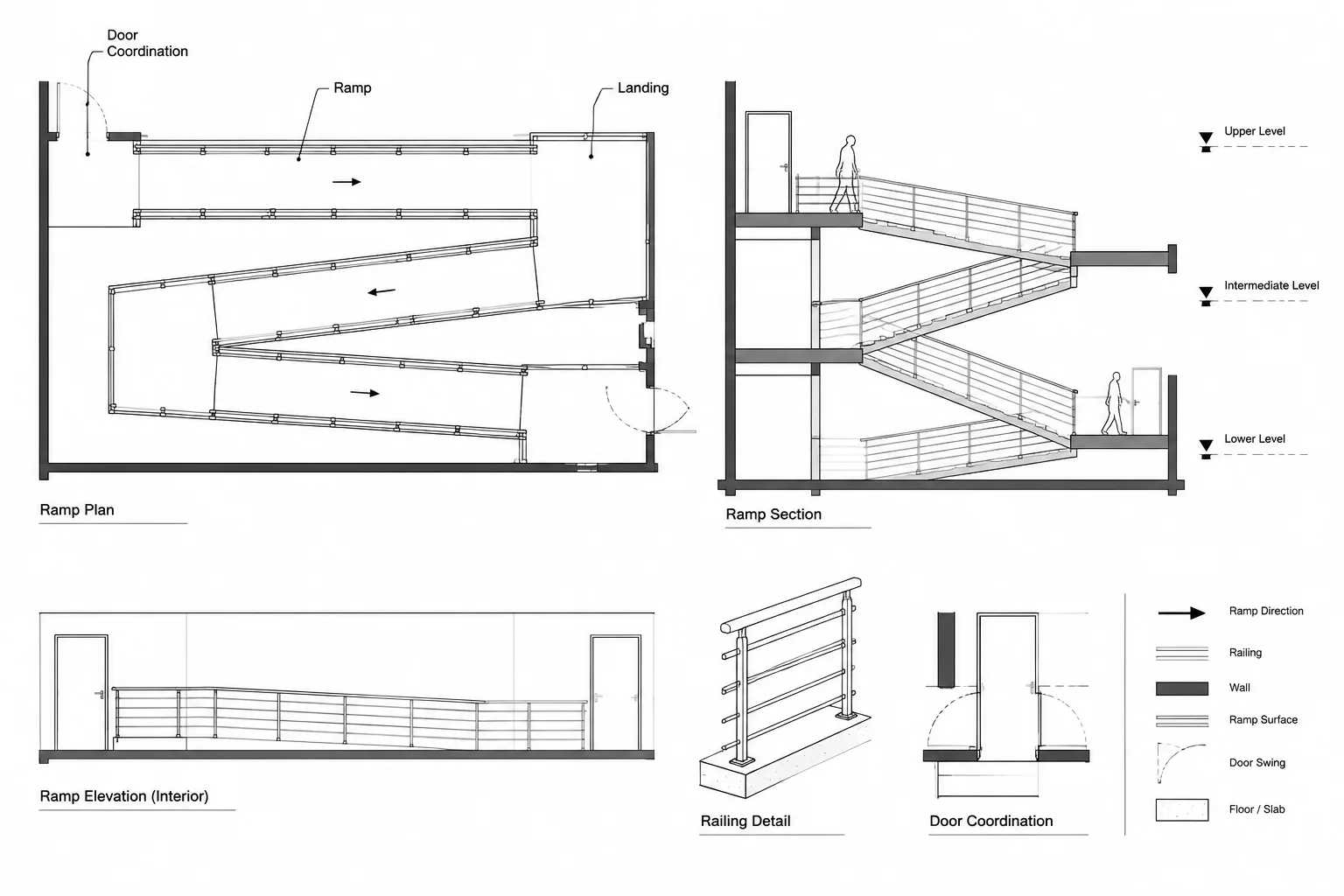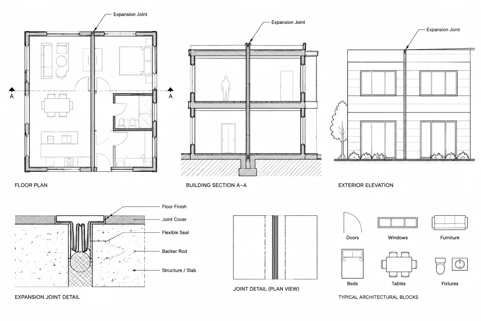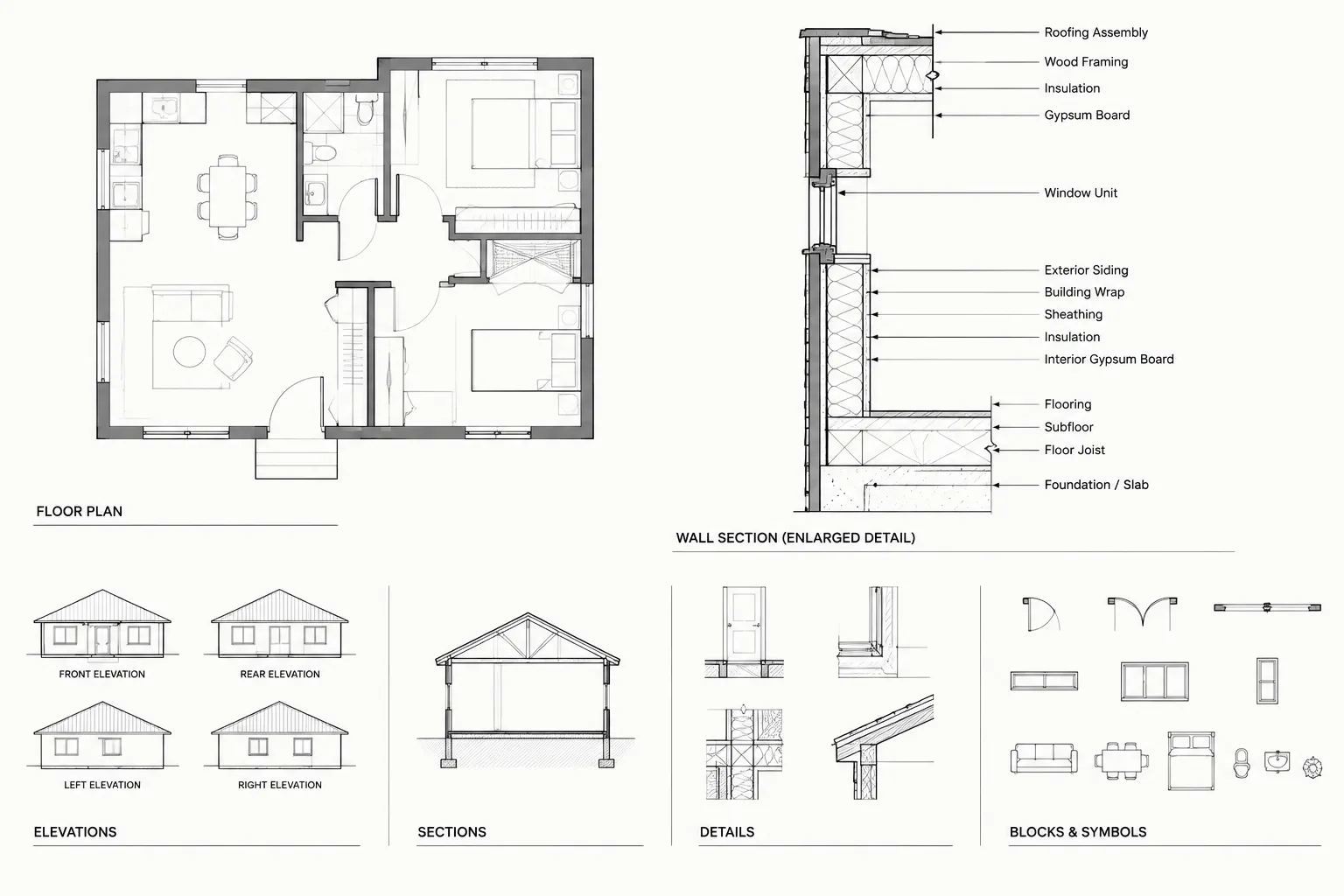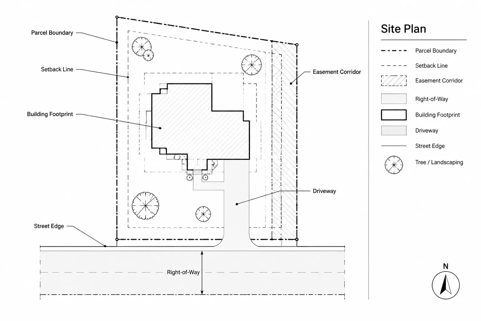
Drafting tile patterns in architectural CAD requires more than filling a room with repeated linework. The pattern must communicate design intent while remaining coordinated with walls, openings, fixtures, finish boundaries, and related construction details.
The following workflow explains how to select an appropriate level of detail, establish a meaningful layout origin, evaluate perimeter conditions, and organize the drawing for efficient revision. It also helps distinguish a graphic finish indication from a setting-out layout that depends on verified product and field information.
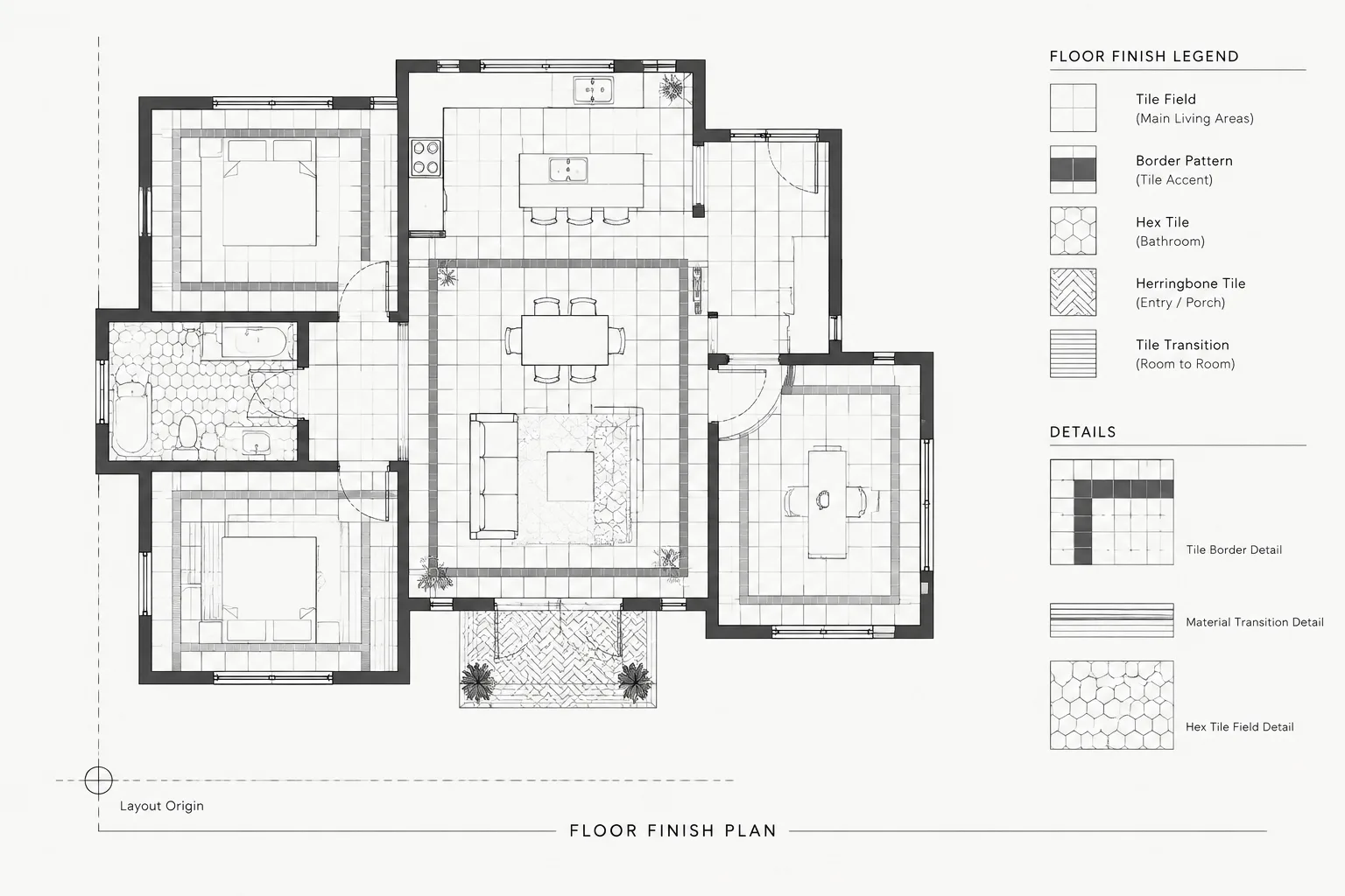
A floor finish plan should communicate more than a hatch pattern. For tile, pavers, wood boards, resilient flooring, and other modular finishes, the drawing may need to establish the layout direction, starting point, joint alignment, borders, transitions, and relationship to fixed architectural elements.
A carefully drafted tile layout in architectural CAD can help the project team identify awkward cuts and coordination problems before installation. However, the drawing must distinguish between a diagrammatic finish indication and a controlled setting-out plan. Adding a dense grid without verifying product dimensions, joint widths, substrate conditions, and field measurements can create false precision.
This workflow explains how to build a clear, editable floor pattern while keeping the information coordinated with plans, interior elevations, schedules, and details.
Decide What the Drawing Needs to Control
Before drawing individual units, determine the intended purpose of the view. Floor finish information can appear at several levels of detail:
- General finish plan: identifies finish types, transitions, and broad pattern directions.
- Enlarged finish plan: shows layout origins, borders, orientation, and relationships to room features.
- Setting-out plan: provides more explicit control of modules, joints, and critical alignments.
- Detail: explains edge conditions, transitions, movement joints, thresholds, or changes in substrate.
Do not use the graphic density of a setting-out plan when a simple finish designation is sufficient. Conversely, a generic hatch may not communicate enough when the design depends on deliberate alignment with walls, doors, drains, counters, or other fixed elements.
Prepare a Reliable Architectural Background
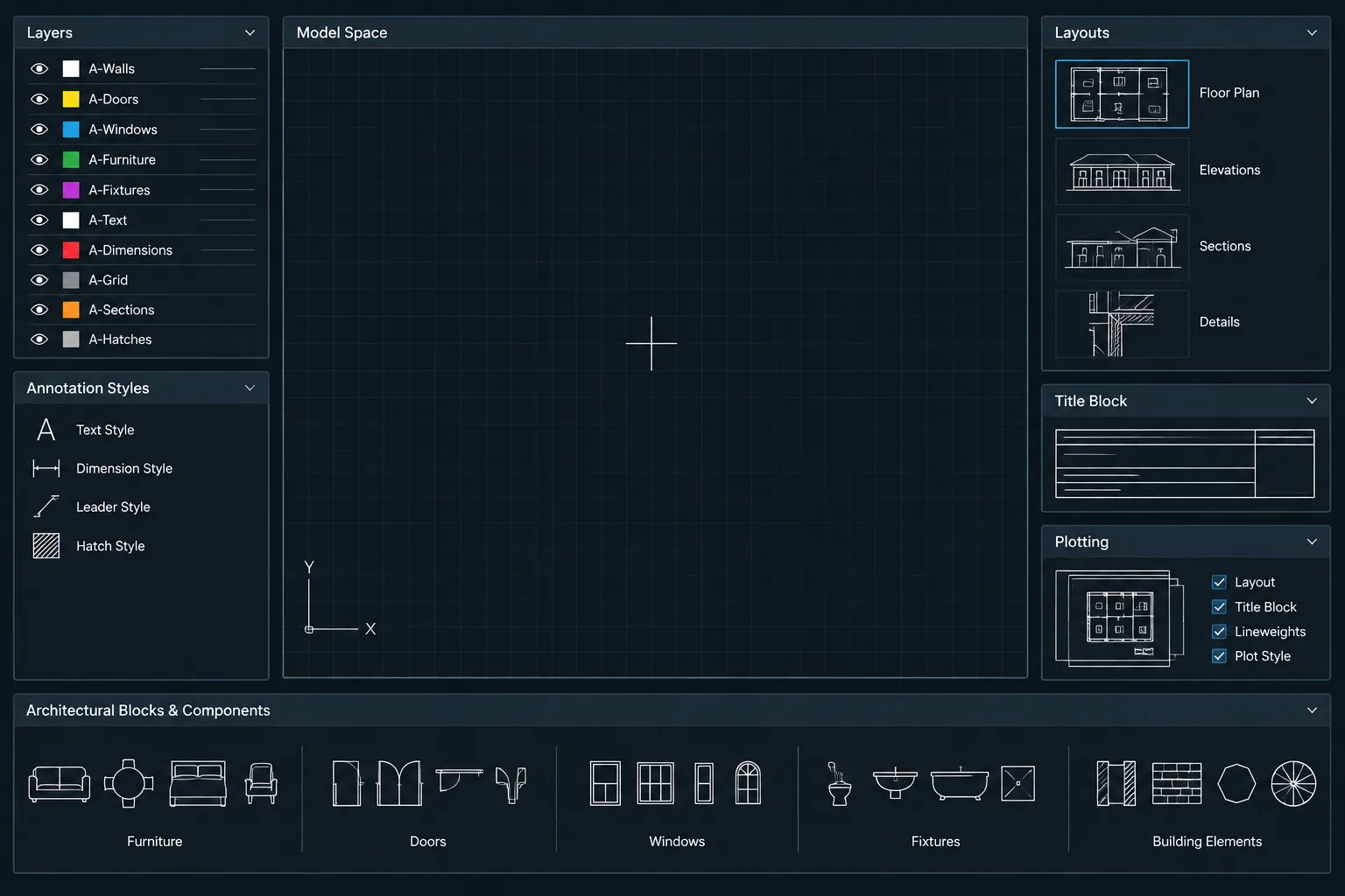
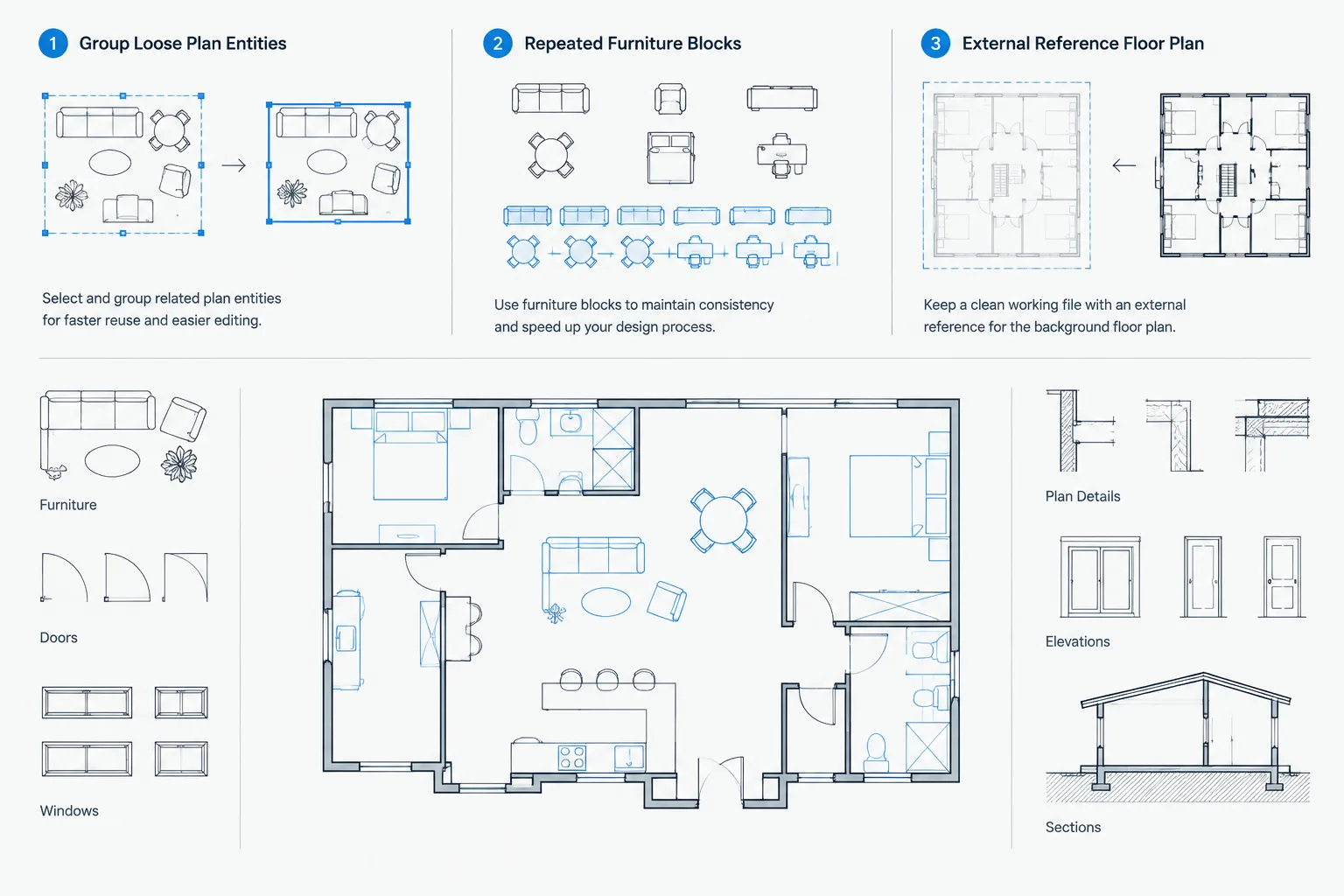
Use a coordinated floor plan as the base. Keep the background separate from the floor pattern so that architectural changes can be updated without rebuilding the entire finish drawing. The base should include the elements that influence layout decisions, such as:
- Finished wall faces and major wall openings
- Columns, pilasters, and permanent casework
- Door openings and threshold locations
- Floor drains, access panels, and other penetrations
- Changes in floor finish or elevation
- Fixed equipment and significant plumbing fixtures
Check drawing units before importing product information or using downloaded CAD blocks. Product literature, consultant files, and project backgrounds may use different unit conventions. A pattern that appears plausible can still be incorrectly scaled.
Separate Finish Boundaries from Pattern Geometry
Create a closed boundary for each finish region before generating the pattern. This boundary represents where the finish changes, not necessarily the full room perimeter. A room may contain several finish fields, a border, an inset area, or a different material beneath fixed equipment.
Keeping boundaries and pattern lines on separate layers makes editing easier. A practical organization may distinguish among:
- Finish area boundaries
- Primary pattern geometry
- Secondary joints or grain lines
- Transitions and divider strips
- Finish tags and layout notes
- Reference or construction geometry
Avoid combining all floor graphics into one block or one undifferentiated layer. The installer-facing pattern may need to be visible in an enlarged plan but screened or hidden in a general floor plan.
Establish a Defensible Layout Origin
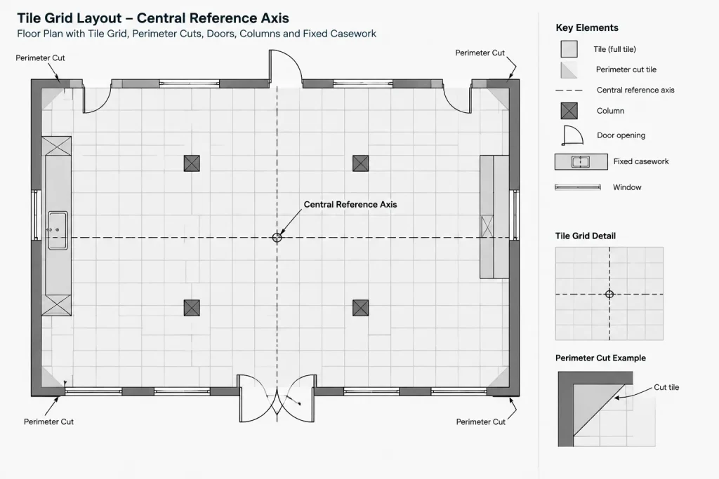
The layout origin is the point or line from which the pattern is set out. It should relate to a stable architectural feature rather than an arbitrary point in the CAD file. Possible references include a primary axis, a prominent opening, a long finished wall, a room centerline, or a feature that continues into an adjacent space.
Test several origins before committing to one. The most visually centered solution is not always the most practical, particularly when walls are not parallel or when a room connects to a larger circulation area.
Evaluate the Perimeter Cuts
Extend the proposed module across the complete finish area and inspect every edge. Look for narrow fragments, uneven cuts at opposite sides, small pieces at corners, and joints that nearly align with architectural elements but visibly miss them.
Do not assume that every wall shown in CAD is straight, parallel, or built exactly as drawn. Where a layout depends on existing construction, field verification and installer coordination may be necessary. Notes should explain the intended design priority without implying that the CAD background is a substitute for site measurement.
Choose the Right Drafting Method
| Method | Best use | Main limitation |
|---|---|---|
| Associative hatch | General finish indication and large areas | May not represent actual unit-by-unit placement |
| Repeated linework | Simple grids and controlled joint alignment | Can become difficult to edit if drawn manually |
| Arrayed module | Repeated units with a deliberate bond or orientation | Requires careful trimming and boundary management |
| Block-based units | Special shapes or units carrying meaningful graphics | Can make the file unnecessarily heavy |
| Simplified diagram | Pattern direction or design intent without exact setting out | Must be clearly identified as diagrammatic |
For a regular tile field, one unit or a small repeat can be copied or arrayed across the boundary and then clipped or trimmed. For a broad finish plan, a hatch may be more efficient. Keep hatch scale and origin consistent where a continuous material passes through multiple spaces.
Avoid tracing every physical feature of a product unless that information is necessary. Surface texture, bevels, and irregular edges can obscure annotations and increase file size without improving construction communication.
Coordinate Joints, Borders, and Feature Lines
Joint alignment often matters most where the floor meets other designed elements. Review the pattern against:
- Door centerlines and threshold edges
- Wall tile joints shown in interior elevations
- Floor drains and plumbing fixtures
- Cabinet faces, islands, and equipment bases
- Columns and structural grids
- Ceiling features when visual alignment is intentional
- Changes in material, color, or laying direction
Do not force unrelated systems into alignment without confirming the design intent. A reflected ceiling grid, wall panel joint, and floor tile joint may use different modules. If alignment is important, identify a shared reference line and coordinate it across the relevant drawings.
Draft borders as separate controlled regions rather than as decorative lines placed over the main field. Show how the field terminates at corners, doorways, and irregular edges. If a border changes the available width of the central field, recalculate the field layout after the border is established.
Show Transitions Clearly
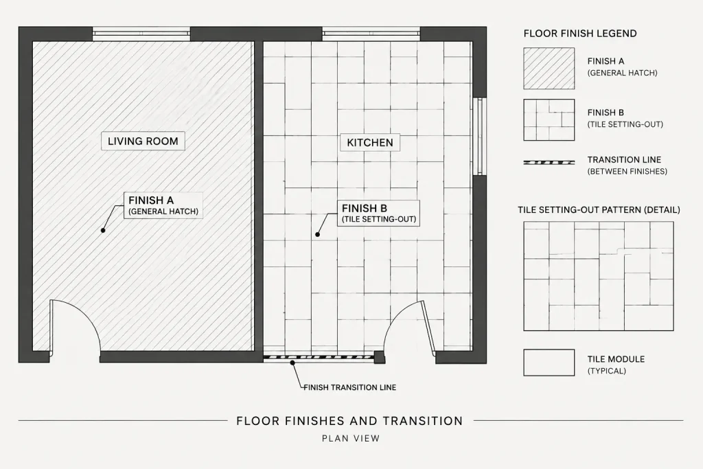
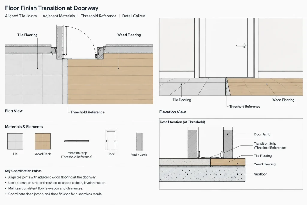
A finish transition is both a plan location and a construction condition. In plan, identify precisely where one finish stops and another begins. The intended line may align with a door leaf, the center of a partition, a finished wall face, a casework edge, or another project-specific reference.
Use a consistent transition symbol or line type and connect it to the appropriate finish tags or notes. Where the materials have different thicknesses, installation methods, or edge requirements, reference a separate detail rather than attempting to explain the entire assembly in plan.
Coordinate the plan with door schedules and threshold details. A transition line that drifts between drawings can lead to visible discrepancies in the completed work.
Control Graphic Hierarchy
Floor patterns should remain subordinate to walls, openings, tags, and critical dimensions. Dense linework can easily overwhelm an enlarged plan. Use lighter plotting for repetitive pattern geometry and stronger graphics for finish boundaries, transitions, and key setting-out lines.
Test the actual plotted output rather than judging only from model space. If joints merge into a dark tone, simplify the pattern, reduce its visual weight, or reserve the detailed layout for a larger-scale view. Background elements may also need screening so that the finish information reads clearly.
Add Only Useful Dimensions and Notes
Dimension the information needed to establish the design intent. This may include an origin line, a controlled border, a transition location, or a feature alignment. Avoid dimensioning every repeated joint when the verified module and starting point already establish the sequence.
Notes should clarify priorities such as maintaining alignment through an opening, centering a pattern on a feature, or coordinating final layout with field conditions. Product sizes, joint widths, and installation requirements should come from verified project documentation rather than assumptions made during CAD drafting.
Run a Coordination Check Before Issue
- Confirm that each finish area has a clear boundary and designation.
- Verify that pattern direction agrees with the finish schedule and design intent.
- Check perimeter cuts, corners, recesses, and door openings.
- Review borders and inset fields as complete systems.
- Confirm transitions against plans, elevations, schedules, and details.
- Check drains, access panels, columns, casework, and fixed equipment.
- Remove duplicate lines and stray geometry outside finish boundaries.
- Confirm that hatches and repeated modules plot legibly at the sheet scale.
- Identify diagrammatic layouts so they are not mistaken for verified setting-out information.
- Require field verification where existing or as-built conditions control the final placement.
Keep the Drawing Editable
Finish layouts often change as products, room dimensions, and equipment locations develop. Preserve the layout logic by retaining construction centerlines, named origin references, and clean boundaries on non-plot or controlled reference layers. Use repeated geometry that can be adjusted systematically instead of unrelated lines trimmed one by one.
A successful CAD floor pattern is not simply an attractive grid. It communicates where the layout begins, how it relates to the architecture, which alignments matter, and where additional verification is required. That combination makes the drawing useful for design review, coordination, and eventual construction documentation without claiming more precision than the project information can support.
Review the Layout as a Coordination Drawing
After drafting the pattern, review it as part of the architectural document set rather than as an isolated graphic. Temporarily reduce the visual emphasis of the repeated joints and examine the finish boundaries, origin references, transitions, and critical alignments. These elements should remain understandable even when the pattern is visually subdued.
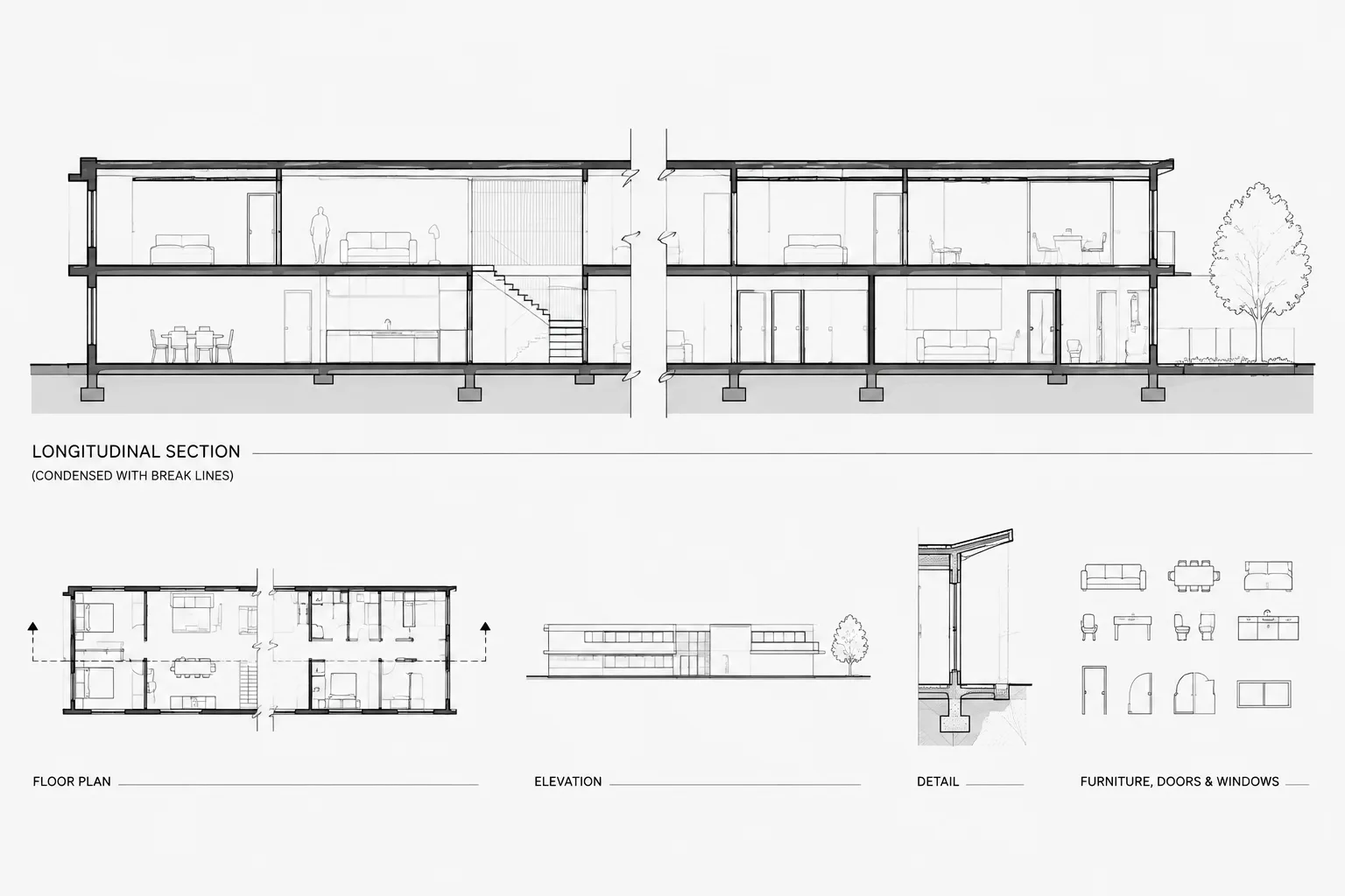
Then compare the plan with the relevant elevations, finish information, door conditions, casework, plumbing fixtures, and floor details. If these views describe different transition locations or competing alignment priorities, resolve the conflict before refining the pattern geometry.
Diagnose Common Pattern Problems
- The layout looks centered but produces awkward edges: test the origin against the complete finish boundary, including recesses, borders, and connected spaces.
- Joints appear to drift between rooms: confirm whether the finish is intended to continue from a shared reference or restart independently in each area.
- The file becomes difficult to edit: separate boundaries, repeated geometry, annotations, and reference construction so revisions do not require rebuilding the entire pattern.
- The plotted plan appears too dark: simplify nonessential surface graphics and strengthen only the boundaries, transitions, and controlling lines.
- The pattern conflicts with fixtures or penetrations: verify which element controls the layout and document that priority instead of making an uncoordinated visual adjustment.
- The drawing suggests unsupported accuracy: identify diagrammatic information clearly and reserve installation-level control for layouts based on verified project data.
Communicate Intent Without Over-Drafting
The most useful floor finish drawing makes its hierarchy clear. Readers should be able to identify the finish areas, understand the pattern direction, locate important transitions, and recognize the references that control placement. Geometry that does not support one of those tasks may be unnecessary.
Before issue, confirm that the chosen drafting method matches the purpose of the view. A simple finish plan can remain diagrammatic, while an enlarged layout may require explicit origins and joint relationships. In either case, the CAD drawing should support coordination without replacing product verification, field measurement, or project-specific professional review.
Frequently Asked Questions
Should a tile pattern be drawn with a hatch or individual units?
Use a hatch when the drawing only needs to identify a finish, general direction, or broad pattern. Use repeated geometry when individual joints, bonds, borders, or alignments are important to the design. The drafting method should match the information the view is intended to control.
Where should a tile layout begin?
Begin from a stable architectural reference that supports the design intent, such as a finished wall, room axis, prominent opening, or shared alignment through connected spaces. Test the proposed origin against the entire finish area before treating it as final.
How should patterns continue through adjoining rooms?
First determine whether the material and design are intended to read as one continuous field. If so, use a shared reference and coordinate joints at openings and transitions. If each room has an independent layout, show where the pattern restarts so the change is not mistaken for a drafting error.
How should irregular or existing walls be handled?
Use the CAD background to study likely cuts and visual relationships, but do not assume that existing construction matches the drawing exactly. Where perimeter conditions control the finished appearance, state the design priority and require appropriate field verification.
What information belongs on a floor finish plan?
Include finish boundaries, finish designations, pattern direction, significant transitions, and any origin or alignment needed to explain the intent. Detailed edge assemblies, substrate changes, and material interfaces are generally clearer in referenced details.
How can dense floor patterns remain legible?
Keep repetitive joints visually lighter than walls, openings, tags, dimensions, and transition lines. Review the plotted result, simplify nonessential graphics, and move highly detailed layout information to an appropriately enlarged view when necessary.