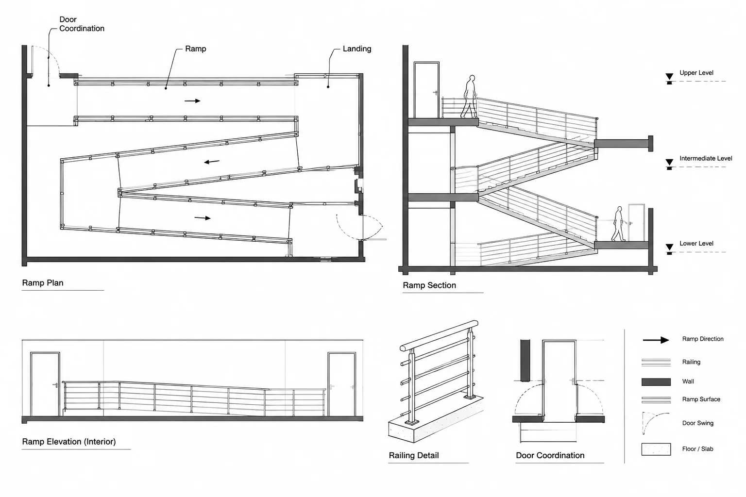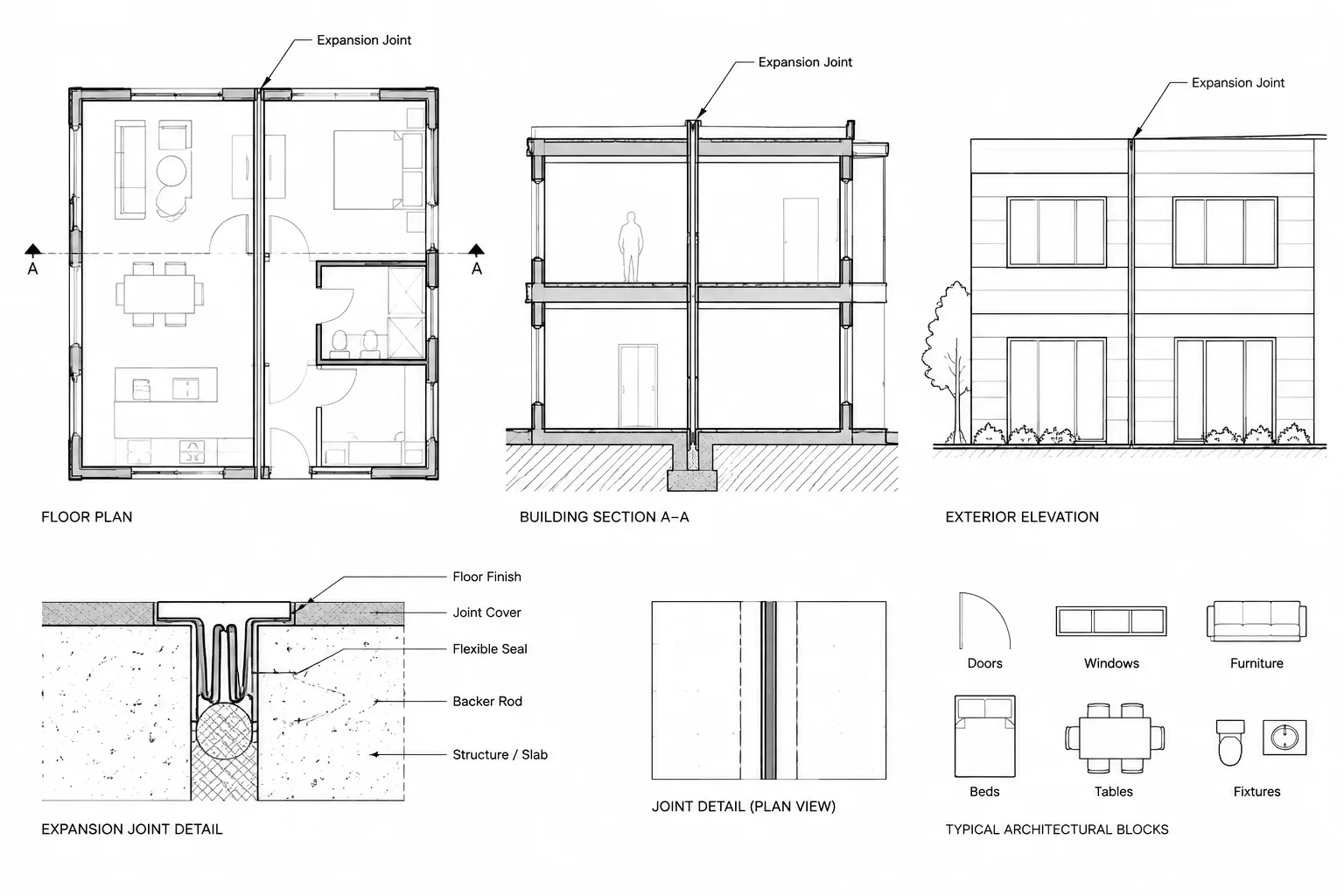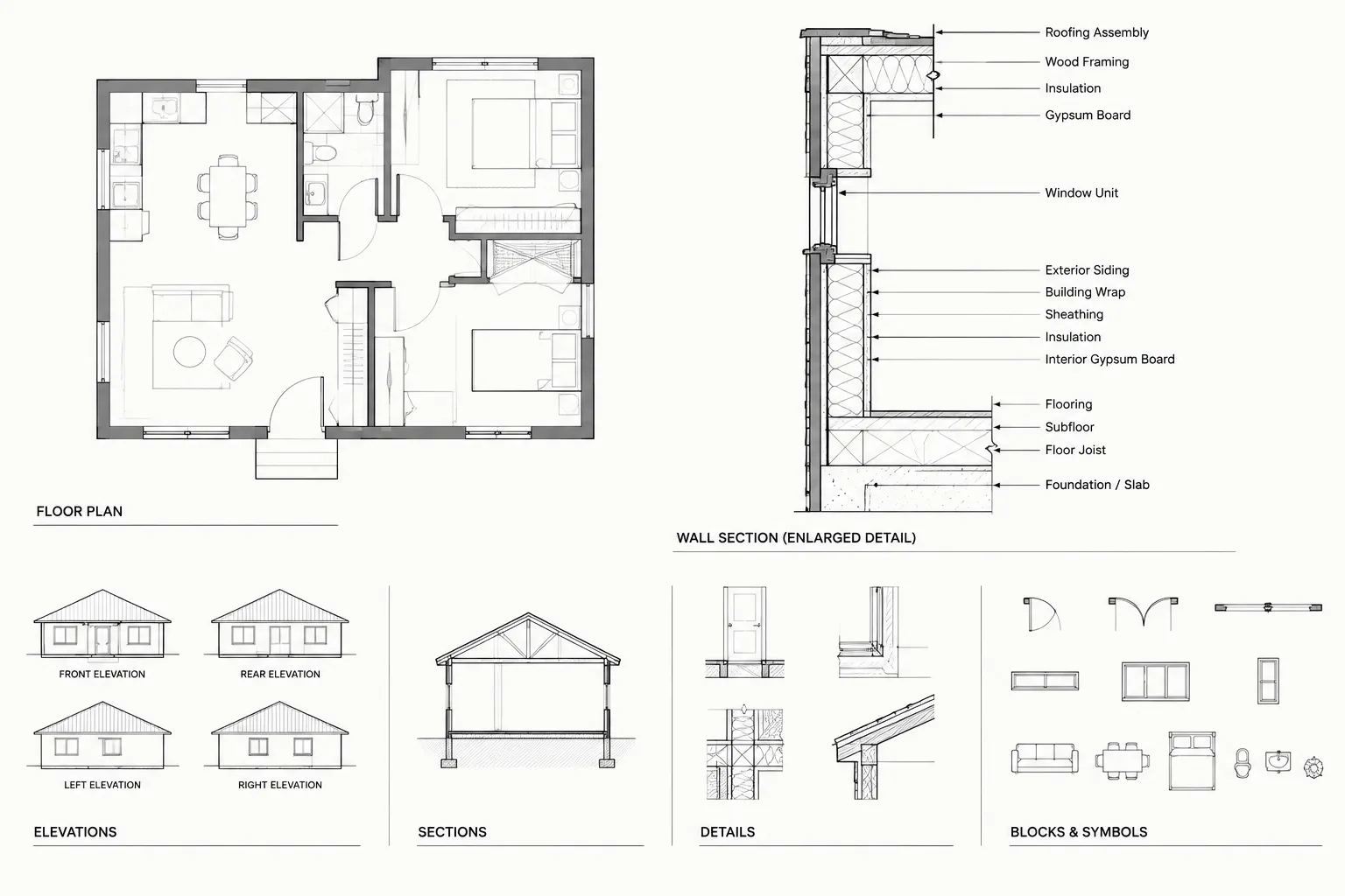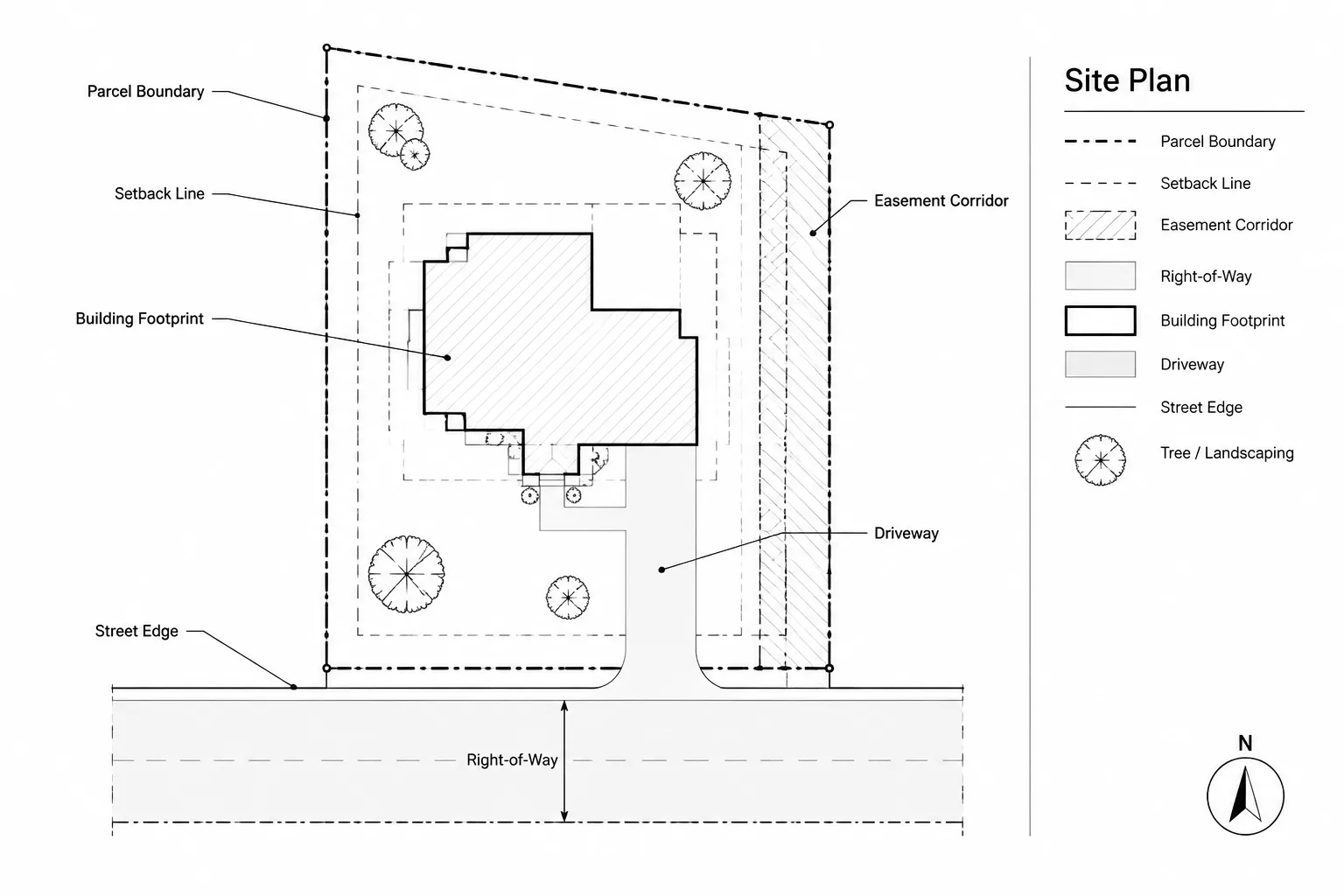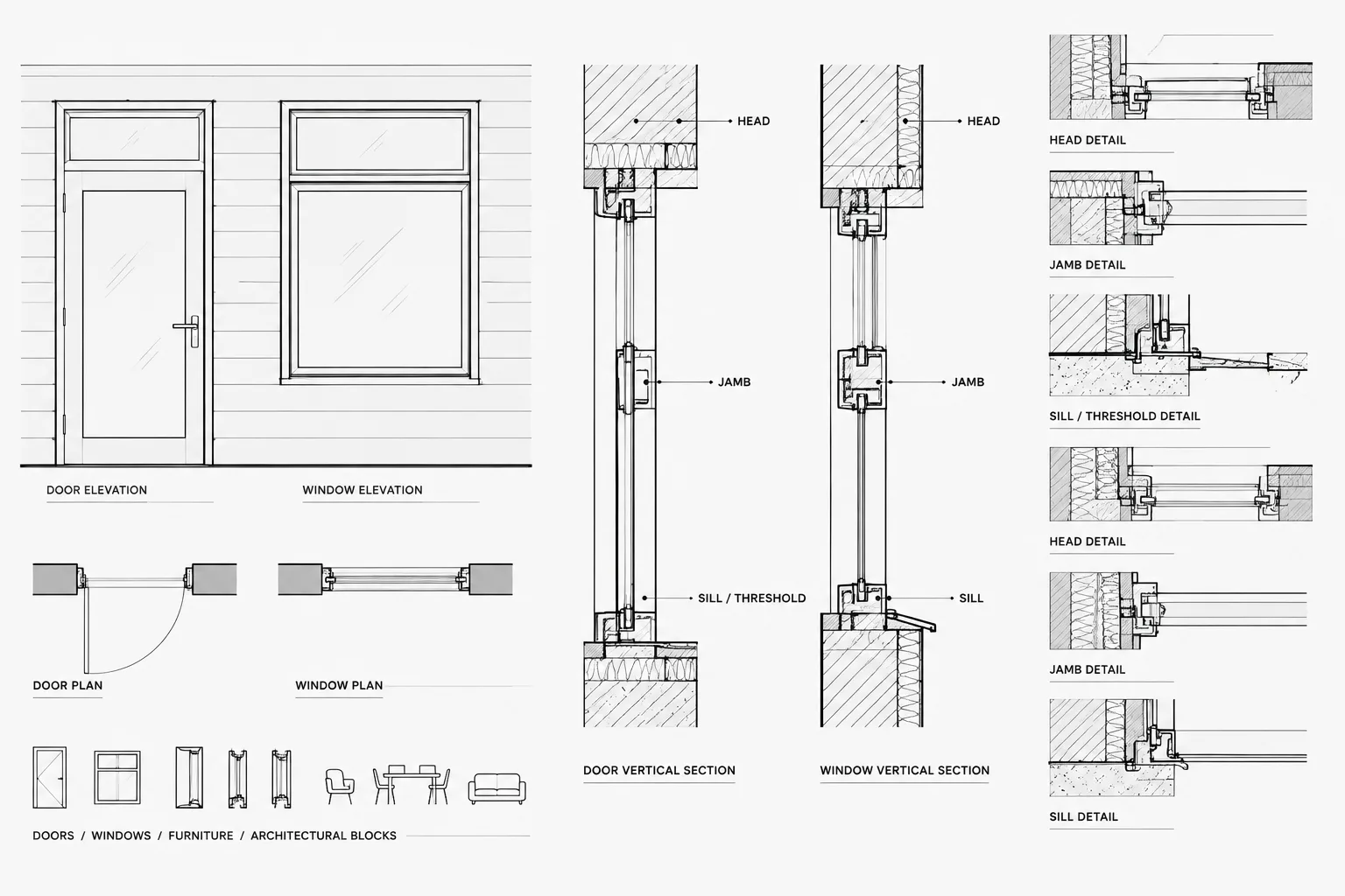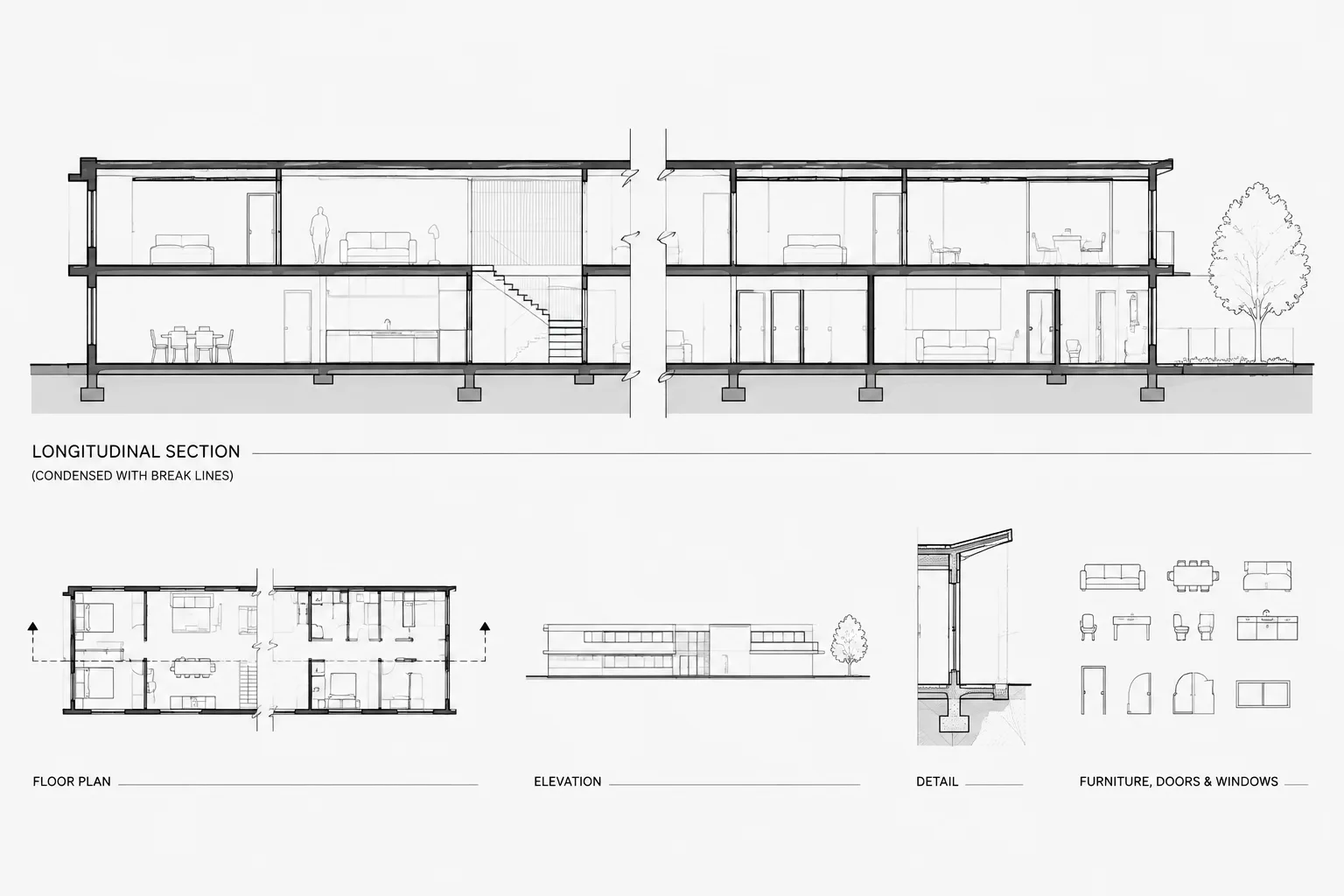
Break lines in architectural CAD can make an oversized or repetitive view easier to place on a sheet, but they also create an important drafting obligation: the omitted area must remain understandable. The symbol, visible geometry, dimensions, notes, and related views must work together so readers do not mistake a condensed presentation for the actual design condition.
This guide explains how to choose between a break, crop, match line, and partial view; manage the underlying CAD geometry; and check the finished drawing for coordination problems.
Break lines allow an architectural drawing to omit repetitive or unnecessary portions of an object while keeping the important construction information visible. They are commonly used in wall sections, millwork elevations, stair details, long corridors, site elements, and other views that would otherwise consume excessive sheet space.
A break line is not merely a graphic shortcut. It changes how a reader interprets the geometry. If the symbol is unclear, a shortened element may be mistaken for its actual length, dimensions may appear to refer to the wrong points, or a continuation may be overlooked. A reliable CAD workflow therefore combines the break symbol with deliberate view boundaries, dimensions, notes, and references.
What a Break Line Communicates
A break line indicates that part of the represented object or view has been intentionally omitted. The geometry shown on opposite sides of the break should be understood as belonging to the same continuous condition unless notes or details state otherwise.
Typical applications include:
- Shortening a long, uniform wall or corridor elevation.
- Removing an repetitive middle portion of a railing, shelf, counter, or cabinet run.
- Condensing a tall section where an intermediate area contains no relevant detail.
- Showing only the end conditions of a linear architectural component.
- Limiting a detail to the area needed for coordination or construction explanation.
The break should remove only information that does not affect the reader’s understanding. Changes in material, alignment, level, assembly, support, or finish should not be hidden simply to make a view fit.
Break Line, View Crop, and Match Line Are Not the Same
Several architectural graphics can limit what appears in a view, but they have different meanings. Using them interchangeably can create coordination problems.
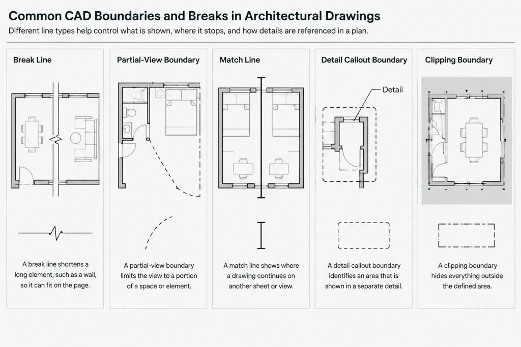
| Graphic device | Primary purpose | What the reader should understand |
|---|---|---|
| Break line | Omits part of an object or view | The condition continues across an intentionally removed portion |
| Partial-view boundary | Limits the area presented | Information beyond the boundary is outside the scope of that view |
| Match line | Divides a larger plan or view between drawings | The drawing continues at a referenced location on another view or sheet |
| Detail callout boundary | Identifies an area shown at greater detail | The enclosed area is referenced by a separate enlarged view |
| Object clipping boundary | Controls CAD display of referenced or inserted content | The boundary may be a drafting control rather than a plotted architectural symbol |
A clipped external reference, for example, does not automatically tell a drawing reader why information stops. If the edge must communicate continuation or omission, add the appropriate plotted graphic and reference rather than relying on the clipping operation alone.
Choose the Right Type of Break
Short break
A short break crosses a relatively narrow object, such as a rail, pipe-like architectural element, trim member, or isolated linear component. Its graphic shape should be recognizable at the intended plotted scale without overwhelming the object.
Long break
A long break is useful across broad walls, elevations, sections, or extended assemblies. It typically interrupts the view with a controlled irregular or zigzag boundary. The line should remain visually distinct from material hatching, demolition graphics, property lines, and hidden elements.
Paired breaks
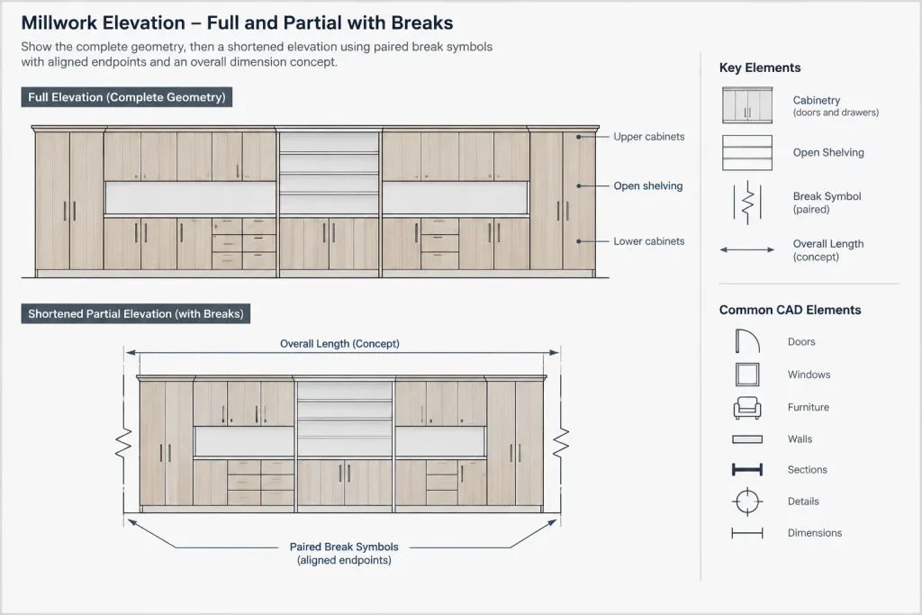
Two corresponding break locations can remove the middle of a long element. Both sides should align logically so the reader can reconstruct the omitted continuity. Paired breaks are particularly useful for repetitive millwork and linear details, but they require careful dimensioning because the displayed graphic length is not the actual length.
A Practical CAD Drafting Workflow
Start with the complete geometry
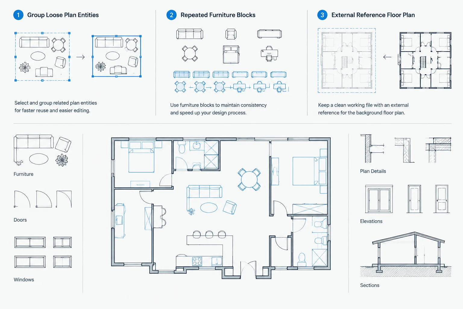
Whenever possible, draw or reference the full object before creating the partial presentation. Complete geometry is easier to coordinate with plans, sections, consultant backgrounds, and adjacent details. Shortening the source geometry too early can introduce false endpoints and make later revisions difficult.
Decide whether the omission is appropriate
Review the area proposed for removal. Confirm that it contains no opening, joint, support, slope change, material transition, level change, control point, or other condition needed to understand the design. If an intermediate feature matters, retain it or create separate partial views with clear references.
Create a plotted break graphic
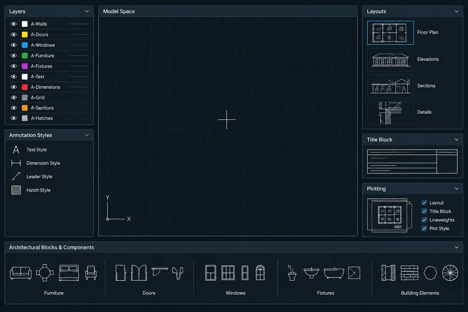
Place break symbols on a dedicated annotation or view-graphics layer consistent with the project’s layer system. A reusable block can improve consistency, but it should be easy to stretch or scale for the plotted view without distorting unrelated geometry.
A useful break-line block should have:
- A logical insertion point tied to the object being interrupted.
- Simple linework that remains legible when plotted.
- By-layer color, linetype, and lineweight behavior where appropriate.
- No embedded labels that become backward when mirrored.
- A clearly named definition that distinguishes it from match lines and detail boundaries.
Control the underlying display
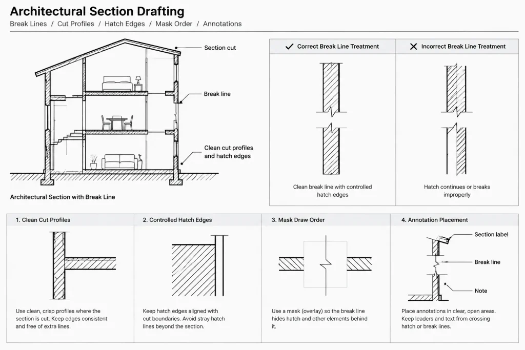
Do not place a break symbol over visible geometry and assume the result is complete. The omitted portion may need to be trimmed, hidden through viewport-specific layer control, covered with a carefully managed mask, or excluded using a clipping method. Select the method that preserves coordination and avoids damaging the source drawing.
If a mask is used, check draw order and plotting. Masks can unintentionally cover dimensions, hatches, grids, or reference markers. If geometry is trimmed, keep a coordinated source or construction reference so the actual object can be restored and revised.
Restore cut profiles and poche
In sections and details, removing part of a view can interrupt wall outlines, cut profiles, insulation graphics, or material hatches. Clean the edges on both sides of the break so each remaining portion reads as a deliberate partial view rather than an accidentally erased drawing.
Add dimensions based on real geometry
A broken view should not be measured from its shortened graphic representation. Dimension the actual design condition using reliable points from the complete geometry or coordinated reference. Avoid dimension chains that appear to cross the omitted gap without making their endpoints clear.
When the overall dimension is important, position it so the reader understands that it describes the full object rather than the displayed distance on the sheet. Intermediate dimensions should remain associated with visible features whenever practical.
Review labels and references
Room names, material notes, keynote leaders, grid references, and level markers can become misleading after a view is condensed. Reposition annotations rather than allowing leaders to pass through the break. If the view continues elsewhere, use a proper reference marker instead of expecting the break symbol to serve as navigation.
Model Space and Paper Space Considerations
Break graphics can be created in model space or paper space, but the choice should follow the drawing’s annotation strategy. A model-space break can remain attached to the geometry and appear in multiple views, which may be undesirable if only one viewport needs the shortened presentation. A paper-space break is view-specific, but it can become disconnected from model revisions.
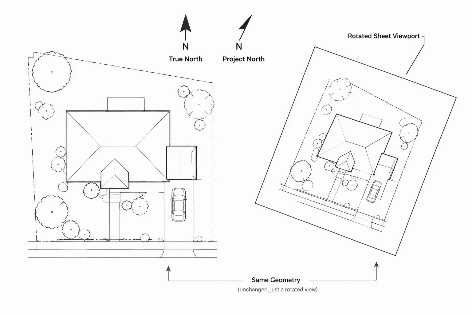
Another option is to use view-specific layers or clipped references while placing the explanatory break graphic in the sheet annotation environment. Whichever method is selected, test the result in every affected viewport. A break intended for one detail should not unexpectedly appear in another elevation or section.
Common Break-Line Errors
- Hiding meaningful variation: The omitted area contains a change that affects construction or coordination.
- Using a match line as a break: The drawing implies continuation on another sheet even though no corresponding view exists.
- Dimensioning the shortened image: A displayed distance is treated as the actual object length.
- Leaving background geometry visible: Lines, hatches, or reference files continue through the break symbol.
- Masking important annotation: Draw order causes dimensions or notes to disappear.
- Breaking only one related view: A partial elevation no longer coordinates clearly with its plan or section reference.
- Using an oversized symbol: The break dominates the detail and obscures nearby construction information.
- Relying on a viewport crop alone: The reader cannot tell whether the view ends, continues, or has been intentionally condensed.
Quality-Control Checklist
- Confirm that the omitted portion is repetitive and contains no necessary design information.
- Verify that break graphics are on the intended plotted layer.
- Check lineweight and readability at the final sheet scale.
- Confirm that dimensions refer to actual geometry and unambiguous endpoints.
- Review masks, clipping boundaries, hatches, and draw order.
- Check that notes and leaders do not cross the omitted area confusingly.
- Compare the partial view with related plans, elevations, and sections.
- Make sure any continuation to another drawing has a valid reference.
- Plot or preview the sheet rather than judging only from model-space display.
Use Breaks to Clarify, Not Conceal
An effective break line saves sheet space while preserving the design information needed to interpret the drawing. The best result begins with coordinated full geometry, removes only genuinely repetitive content, and uses annotation that clearly explains the shortened presentation.
Treat every break as a communication decision. If omitting an area makes dimensions, materials, levels, or references harder to understand, a larger view, a different scale, or an additional detail is usually a better solution.
A Decision Sequence for Partial Views
Before adding a break symbol, identify what the drawing needs to communicate. If the view must continue on another drawing, use a continuation reference rather than treating the condition as a simple omission. If information outside the displayed area is irrelevant to the purpose of the view, a partial-view boundary may be clearer. Use a break when the reader needs to understand that separated visible portions belong to the same continuous condition.
Test the omitted area
Temporarily isolate the proposed gap and review everything that would disappear. Look beyond primary outlines to include joints, patterns, supports, openings, level information, leaders, and reference markers. If removing the area changes how the assembly could be interpreted, revise the view strategy rather than relying on an explanatory note alone.
Separate design geometry from presentation graphics
Maintain a clear distinction between geometry describing the design and graphics controlling its sheet presentation. This makes it easier to revise the full condition, reuse it in another viewport, and audit dimensions against dependable points. Layer naming and block naming should also make the break symbol easy to distinguish from clipping boundaries and continuation markers.
Check the drawing as a reader would
Review the plotted composition without depending on editing aids or knowledge of the full model. The remaining portions should align logically, dimensions should identify meaningful endpoints, and the break should not resemble a material edge or construction joint. Related plans, sections, and elevations should provide a consistent account of the condition.
Coordination During Revisions
Partial views deserve additional attention when geometry changes. A revision can move a feature into the omitted area, alter a dimension endpoint, or expose background linework that was previously covered. Include broken and cropped views in drawing-update reviews instead of assuming that changes to the complete geometry will automatically produce a correct sheet presentation.
For team workflows, make the display method understandable to the next drafter. Clearly organized source geometry, view controls, masks, annotation layers, and reusable symbols reduce the risk that someone edits only the shortened representation while leaving the coordinated design unchanged.
Frequently Asked Questions
Does a break line mean that an object ends?
No. It normally indicates that an intermediate portion has been intentionally omitted from the representation. The visible parts should still communicate continuity unless another note or detail explains a different condition.
Can a viewport crop replace a plotted break symbol?
Not necessarily. A crop controls what the CAD viewport displays, but it may not explain to a drawing reader whether the condition ends, continues, or has been condensed. Add an appropriate plotted graphic when that distinction matters.
Should the original geometry be shortened to match the broken view?
Keeping complete, coordinated geometry is generally the safer workflow. The shortened appearance can then be managed as a view-specific presentation without creating false design endpoints. The appropriate method still depends on the drawing organization and team standards.
How should dimensions work across an omitted area?
Dimensions should describe the actual design condition and use dependable endpoints. Their placement must make it clear that the value relates to the complete object rather than the shorter distance visible on the sheet.
When is a match line more appropriate than a break line?
Use a match line when the drawing continues in another referenced view or sheet location. A break line instead communicates that part of the same condition has been omitted from the displayed representation.
Why can masks cause problems in broken views?
A mask can cover more than the intended geometry. Changes in draw order or viewport content may hide hatches, dimensions, grids, or notes, so the plotted result should be checked after revisions.