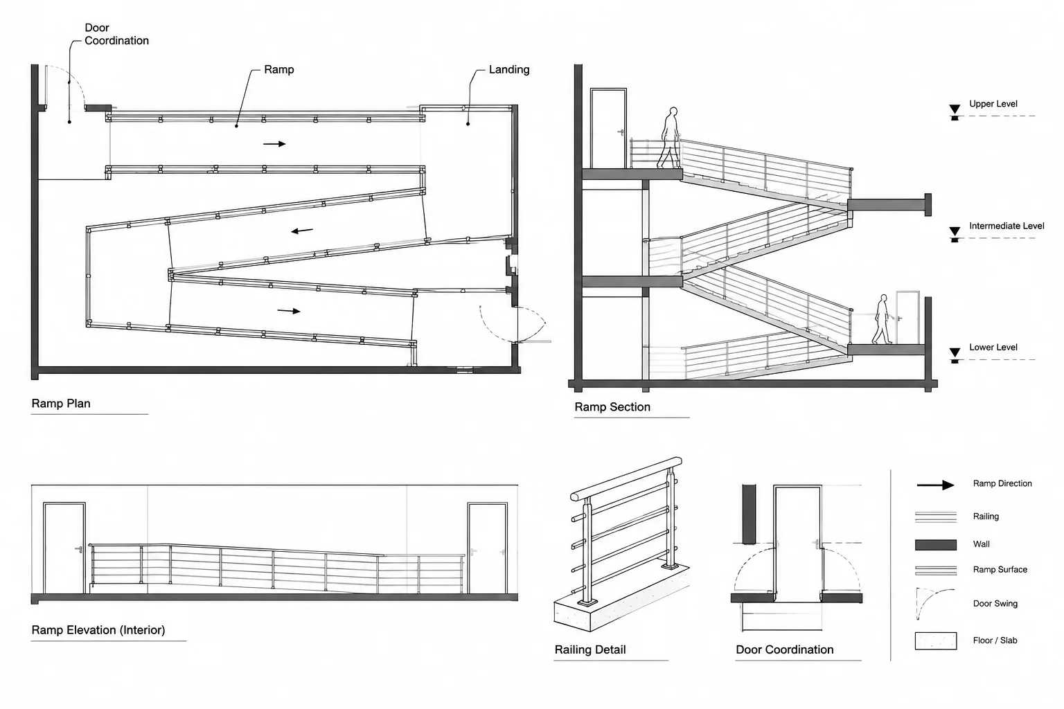
To draft ramps and landings in CAD accurately, treat the route as a coordinated vertical transition rather than a standalone plan symbol. Elevations, sloped runs, level landings, doors, edge conditions, drainage, and adjoining construction must remain consistent across every relevant view.
This guide outlines a practical architectural drafting workflow for building editable ramp geometry, organizing information, and checking coordination. It does not replace the accessibility criteria, building regulations, consultant requirements, or manufacturer information applicable to a specific project.
Ramps can appear simple in plan, but they combine horizontal geometry, vertical movement, circulation, drainage, edge protection, and construction detailing. A ramp that looks correct in one view may conflict with a floor level, doorway, railing, structure, or site surface elsewhere in the drawing set.
A reliable CAD workflow begins with verified levels and calculated geometry rather than a ramp block copied from another project. The plan, section, elevation, and detail views should all describe the same path of travel and the same vertical transition. Applicable accessibility rules, building codes, client criteria, and site conditions must be checked for each project and jurisdiction.
Start with the vertical problem
Before drawing the ramp outline, identify the elevations it must connect. Record the lower level, upper level, and total rise using the project’s established elevation datum. Confirm whether each value represents a finished surface, structural surface, or another reference.
Next, determine the allowable slope and landing arrangement from the governing project requirements. Do not estimate the ramp length from appearance. The required horizontal run depends on the verified rise and permitted slope. Changes in floor finish thickness, exterior paving buildup, drainage design, and structural depth can affect the final geometry.
Prepare a short design checklist before drafting:
- Lower and upper finished elevations
- Total vertical rise
- Required clear width
- Permitted slope and cross-slope criteria
- Required landing locations
- Door swings and approach areas
- Railing, handrail, curb, wall, or guard conditions
- Structural support and edge conditions
- Drainage direction for exterior or wet locations
Build the ramp from reference geometry
Draw the ramp using simple, editable construction geometry before adding annotation or detailed components. Establish the centerline or primary travel direction, then locate the beginning and end of the sloped run. Add boundaries based on the required clear width and surrounding construction.
Landings should be drawn as intentional level areas, not as leftover spaces between runs. Their geometry may be affected by a change in direction, a doorway, adjacent walls, columns, or the transition to a sidewalk or corridor. When a ramp turns, verify the inside and outside boundaries as well as the usable path through the landing.
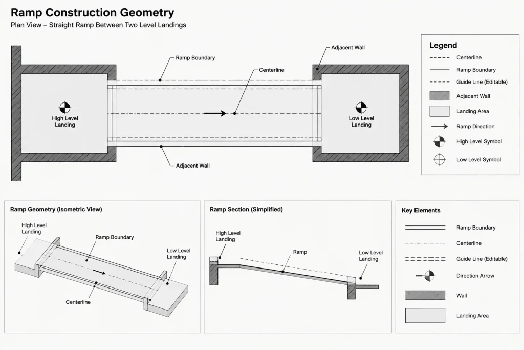
Keep temporary calculation lines on a non-plotting construction layer or another controlled workspace. These references make later adjustments easier and help reviewers understand how the plan geometry was developed.
Avoid relying on a generic ramp block
A reusable block may be helpful for a diagram or early planning study, but it should not control final project geometry. Ramps are highly dependent on actual elevations and adjacent conditions. If a block is used, verify its units, scale, insertion point, orientation, linework, attributes, and embedded annotation before incorporating it into the drawing.
Represent the ramp clearly in plan
The plan view should make the ramp’s direction and limits immediately understandable. Show the visible boundaries, landings, adjacent walls or curbs, and any railings or handrails that affect circulation. Distinguish elements cut by the plan plane from items seen below or overhead using the project’s established graphic hierarchy.
A slope arrow or directional symbol should follow the office convention and be paired with clear level information. Avoid depending on an arrow alone, because its meaning may be misread if the drawing does not identify the high and low points. Use spot elevations, level tags, or coordinated notes at meaningful transitions.
Dimensions should describe geometry without obscuring the route. Depending on the drawing purpose, useful dimensions may include overall width, clear width, run limits, landing extents, offsets from walls or grids, and relationships to nearby doors. Do not duplicate every dimension in multiple views if doing so creates opportunities for conflict.
Develop a coordinating section early
A section is essential for checking whether the ramp actually connects the required levels. Create at least one working section through the direction of travel during design development rather than waiting until the detail stage.
The section should show the lower landing, sloped surface, intermediate or upper landings, adjoining floor or grade, and relevant construction depth. It should also indicate how the ramp meets thresholds, slabs, foundations, paving, or framed floor assemblies.
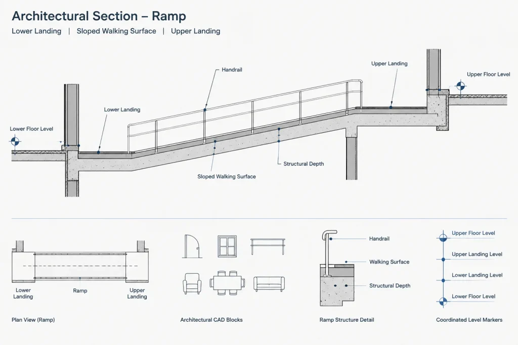
Use the section to verify:
- Consistency between rise, run, and stated slope
- Finished elevations at both ends
- Headroom beneath adjacent construction where relevant
- Transitions between sloped and level surfaces
- Railing and handrail continuity
- Structural depth and support zones
- Exterior drainage and water-management conditions
If the ramp changes direction, one section may not explain the complete route. Add another section, elevation, or unfolded diagram where necessary. Reference each view with coordinated callouts instead of leaving explanatory geometry isolated in model space.
Coordinate railings, handrails, curbs, and walls
Ramp edges are often more complex than two parallel lines. One side may meet a wall while the other has a curb, railing, guard, planter, or open edge. These conditions influence the clear route and should be drafted as separate building elements rather than merged into the ramp outline.
Use distinct layers or object classifications for the walking surface, walls, railings, handrails, curbs, and overhead components. This allows each system to retain an appropriate lineweight and makes coordination easier. Avoid drawing a handrail as part of a wall polyline or embedding every component in one anonymous block.
At landings, check how rails terminate or continue around corners. Coordinate handrail extensions, mounting conditions, posts, brackets, and returns with verified project requirements and manufacturer information. Enlarged plans and sections are usually more useful for these relationships than dense notes on a general floor plan.
Check doors and circulation at landings
Doors near ramps require careful coordination. A door swing can overlap a landing, interrupt a handrail, or create an awkward circulation conflict even when the individual objects appear correct.
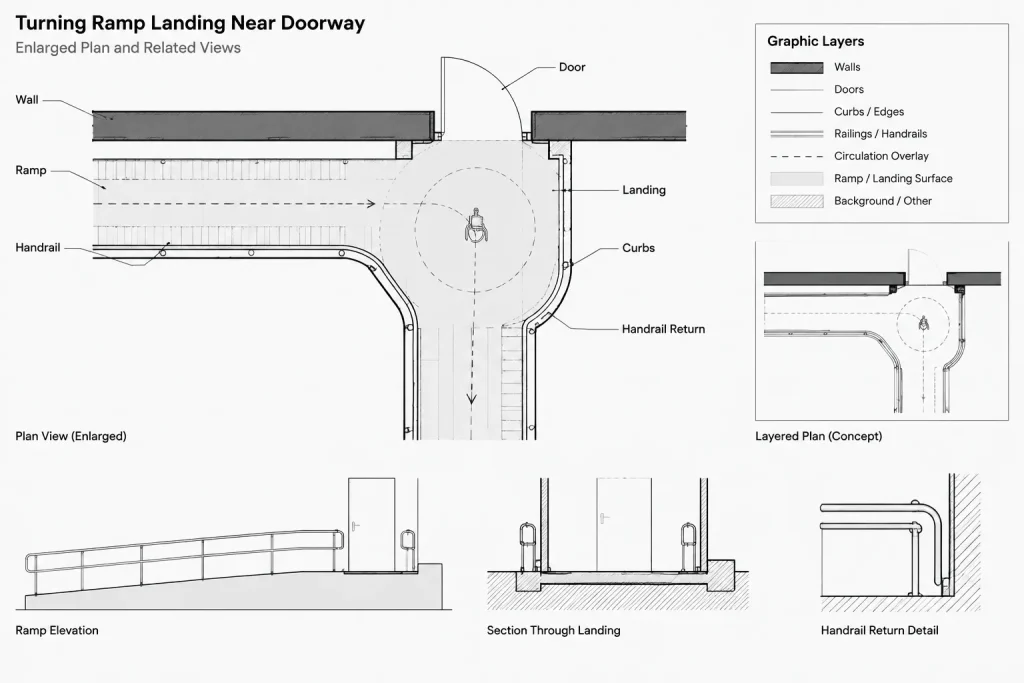
Reference the current door opening and swing geometry, then review the approach from both directions. Confirm that wall returns, frames, hardware-side conditions, thresholds, and nearby railings are represented accurately. Clearance or maneuvering zones may be shown on a controlled non-plot layer during coordination, but their requirements must come from the applicable project criteria rather than a generic downloaded block.
Organize ramp information across the drawing set
| Drawing view | Primary information to show | Common coordination issue |
|---|---|---|
| Floor or site plan | Ramp limits, direction, landings, nearby doors, levels, and overall circulation | Plan geometry does not match calculated rise and run |
| Enlarged plan | Clear route, edge conditions, railings, joints, and detailed dimensions | Handrails or curbs reduce the intended usable width |
| Section | Vertical transition, slope, construction depth, and adjoining surfaces | Finished levels differ from the plan or civil background |
| Elevation | Rail profiles, posts, walls, exposed edges, and terminations | Railing geometry does not follow the ramp or landing |
| Detail | Connections, transitions, edge assemblies, waterproofing, or material interfaces | Generic detail conflicts with the project assembly |
Assign a clear source of truth for each type of information. For example, levels may be controlled by the architectural plan and section, while exterior grading comes from the coordinated civil background. Avoid manually re-creating consultant geometry without tracking later changes.
Use layers and blocks selectively
A practical ramp drawing may use separate layers for surface edges, overhead or concealed lines, railings, centerlines, level symbols, dimensions, notes, and temporary clearance graphics. Follow the project layer standard rather than creating ramp-specific layers that duplicate existing categories.
Blocks work well for repeated symbols such as level markers, section references, and slope arrows. Repeated railing posts or brackets may also use blocks when appropriate. The ramp surface itself is usually better kept as editable project geometry because its shape must respond to changing levels and surrounding construction.
Run a final coordination check
Before issuing the drawing, compare the ramp in every relevant view. Trace the path from the lower level to the upper level and confirm that each transition is represented consistently.
- Recalculate the rise and run from current elevations.
- Confirm that plan dimensions match the section geometry.
- Check that slope arrows agree with high and low level tags.
- Review door swings and circulation at each landing.
- Verify clear width against walls, curbs, rails, and projections.
- Compare architectural levels with structural, civil, and landscape information.
- Check drainage direction and surface transitions where applicable.
- Confirm that detail references point to the correct conditions.
- Plot the sheet and review lineweights, hidden lines, text, and overlapping symbols.
The most dependable ramp drawings are developed as coordinated three-dimensional relationships, even when the deliverable is conventional two-dimensional CAD. Starting with verified levels, maintaining simple reference geometry, and checking the plan against sections and details will produce a clearer drawing and reduce conflicts during later coordination.
Manage ramp revisions without losing coordination
Ramp geometry often changes as finished levels, structural assemblies, grading, doors, or circulation layouts develop. A controlled revision process helps prevent the plan from advancing while sections and details continue to show an earlier condition.
Begin each revision by identifying what caused the change. If an elevation changed, update the vertical calculation and reference geometry before adjusting the visible outline. If a wall, door, or railing moved, verify whether the clear route, landing arrangement, edge treatment, or annotation must also change.
Use a clear update sequence
- Confirm the current inputs: Review the governing levels, adjoining surfaces, project criteria, and consultant backgrounds.
- Revise the controlling geometry: Update construction lines, run limits, landing boundaries, and transitions before moving annotations.
- Propagate the change: Review enlarged plans, sections, elevations, details, schedules, callouts, and referenced backgrounds.
- Check dependent elements: Revisit doors, walls, railings, handrails, curbs, drainage features, joints, and structural supports.
- Review the plotted result: Confirm that line hierarchy, notes, dimensions, level symbols, and directional graphics remain legible.
Separate design references from issued graphics
Temporary slope studies, clearance outlines, construction lines, and consultant comparison marks can support coordination without appearing on the final sheet. Keep them on controlled layers and use an office-approved method to distinguish current information from superseded or reference-only geometry.
Avoid solving discrepancies by stretching visible linework until views appear similar. Return to the established elevation datum and governing geometry, then regenerate or revise each dependent view from the same design intent.
Prepare the drawing for interdisciplinary review
A reviewer should be able to follow the route, identify its high and low points, understand where landings occur, and locate the supporting sections or details. The drawing should also make coordination boundaries clear. Architectural documents may describe the circulation and finish geometry, while structural, civil, landscape, waterproofing, and railing information may be controlled elsewhere in the project set.
Record unresolved conditions instead of concealing them with generic notes. Open issues may include incomplete grading, an unverified threshold, uncertain structural depth, a pending railing system, or a conflict between backgrounds. Resolving those items before issue is more reliable than assuming that a typical detail will apply.
Frequently asked questions
Should a ramp be drafted from the plan or the section first?
Start with verified elevations and the vertical relationship, then develop plan and section geometry together. The plan establishes the route and boundaries, while the section confirms that the route connects the required levels.
Is a slope arrow enough to describe a ramp?
No. A directional symbol can support the drawing, but it should be coordinated with level information and clearly identified transitions. An isolated arrow may be misunderstood if the high and low points are not evident.
Can a downloaded ramp block be used in a construction drawing?
It can serve as reference geometry or an early planning aid, but it should not be assumed to match the project. Verify its units, orientation, clearances, annotation, and relationship to actual elevations before use.
Why do ramp plans and sections become inconsistent?
Common causes include independent editing, outdated consultant backgrounds, changed finish elevations, copied details, and dimensions that are not tied to the current geometry. A controlled update sequence reduces these conflicts.
How should doors near ramp landings be coordinated?
Review the door swing, approach path, frame and threshold conditions, wall returns, nearby railings, and the usable landing area. Apply the accessibility and code criteria adopted for the project rather than relying on a generic clearance block.
What should be checked before issuing a ramp drawing?
Compare current elevations, plan geometry, sections, edge components, door relationships, drainage direction, consultant information, annotations, and detail references. Complete a plotted review so graphic conflicts are visible as they will appear on the sheet.