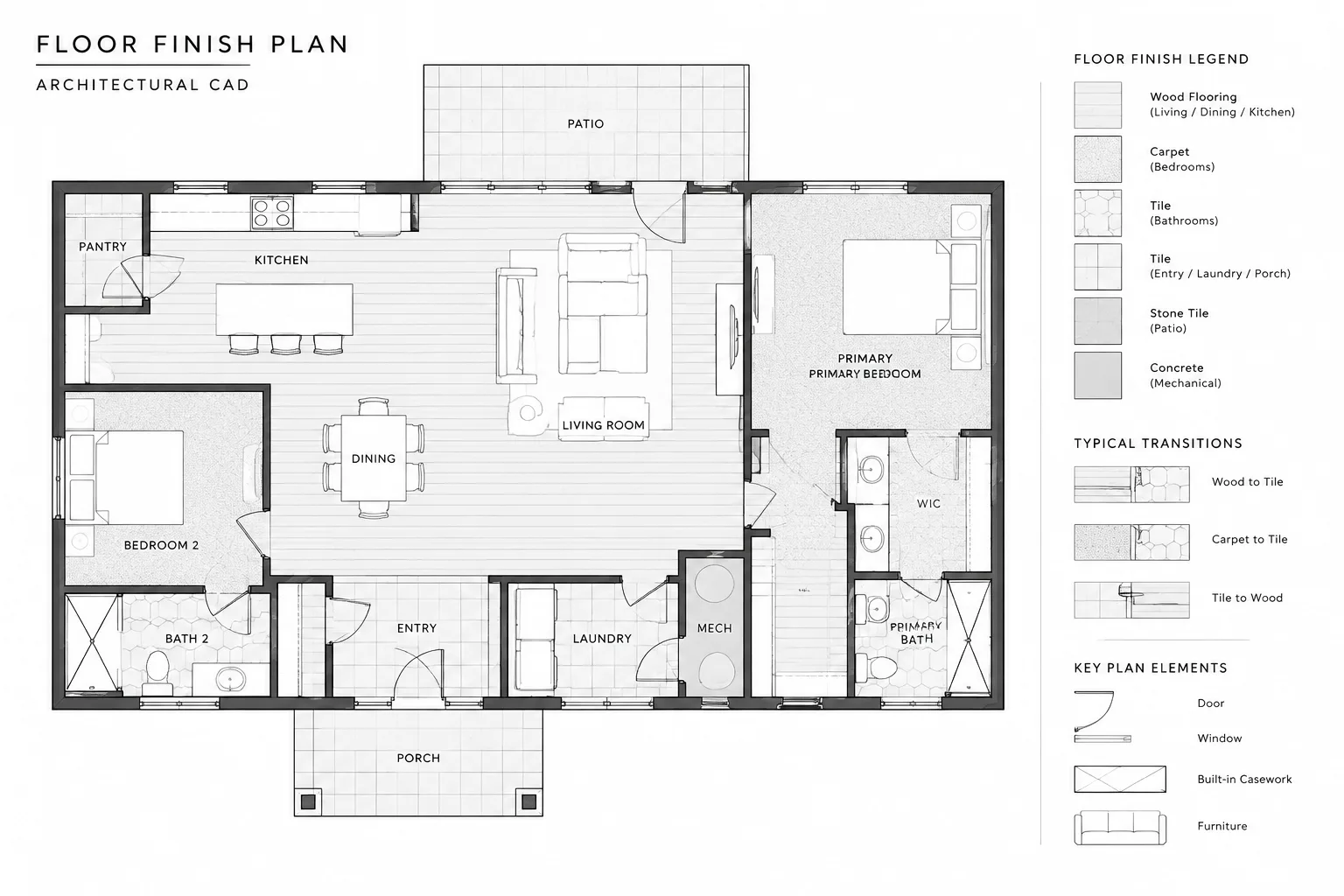
Floor finish boundaries in CAD are construction-document controls, not merely edges used to contain hatch patterns. Each boundary should communicate the intended extent of a material and remain coordinated with doors, walls, fixed elements, level changes, finish identifiers, and related details.
This guide explains how to build maintainable finish regions, locate transitions from meaningful architectural references, manage graphic hierarchy, and review the finished drawing against the wider architectural set. The emphasis is on creating information that remains clear when the design changes and when the plan is plotted for review.
Floor finish drawings do more than identify carpet, tile, resilient flooring, wood, or sealed concrete. They communicate exactly where one finish stops, another begins, and how those transitions relate to walls, doors, casework, fixtures, and changes in floor elevation.
A finish plan can look complete while still leaving important questions unanswered. A boundary may be shown near a doorway without indicating whether it aligns with the door centerline, frame, or wall face. A material tag may identify a finish but not the specific region it applies to. Finish hatches can also obscure architectural linework or make the printed sheet difficult to read.
A reliable CAD workflow treats each finish area as coordinated geometry rather than decorative hatch. The following process helps produce finish plans that are easier to edit, review, schedule, and construct.
Start with a coordinated architectural base
Draft finish boundaries over the current architectural floor plan, not over an isolated copy that can drift out of date. Referenced base drawings are generally easier to coordinate because changes to partitions, doors, openings, casework, and fixtures can be reviewed against the finish layout.
Before adding finish information, confirm that the base plan provides the geometry needed to place boundaries accurately. Pay particular attention to:
- Partition faces and wall openings
- Door locations, frames, and swing direction
- Casework, islands, reception desks, and built-in furniture
- Plumbing fixtures and floor-mounted equipment
- Stair, ramp, and elevator boundaries
- Floor openings, shafts, and recessed areas
- Columns, pilasters, and irregular wall projections
- Exterior entrances and vestibules
If the finish plan is developed before these elements stabilize, use a deliberate review process whenever the base drawing is updated. Do not assume that a revised wall or door automatically produces a coordinated finish boundary.
Separate finish geometry from the architectural base
Place finish boundaries, hatches, tags, and transition symbols on dedicated layers according to the project layer system. Keeping these elements separate makes it possible to adjust their visibility and plotting behavior without modifying the floor-plan geometry.
A practical layer structure may distinguish among:
- Finish boundary linework
- Finish hatch or pattern graphics
- Finish tags and text
- Transition symbols and notes
- Existing finish information, when required
- Demolition or removal information, when required
Avoid placing hatch objects or finish lines on wall, door, furniture, or generic annotation layers. Mixed object types make later editing and graphic control unnecessarily difficult.
Define finish areas with closed, maintainable geometry
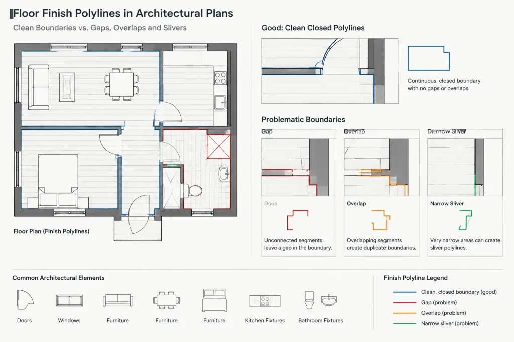
Use closed polylines or another clearly controlled boundary method for finish regions. A finish area assembled from unrelated line segments is more likely to develop gaps, overlaps, and ambiguous corners.
Closed boundaries offer several practical advantages. They can be selected as complete regions, checked for continuity, reused for hatch creation, and adjusted when walls or built-ins move. They also make it easier to identify unintended slivers between adjacent materials.
Do not automatically trace every visible object. Decide which elements actually interrupt the finish. A movable table normally does not create a finish boundary, while a permanent raised base, floor recess, fixed island, or built-in platform may affect the finish geometry. That distinction should follow the project design and construction intent.
Keep boundaries understandable
Complex rooms can produce excessively detailed polylines around columns, casework, and wall offsets. Preserve necessary design information, but avoid tiny segments that result only from imprecise tracing or imported geometry. Simplified, accurate boundaries are easier to hatch and revise.
When neighboring finishes meet, coordinate their edges from the same controlling geometry. Independently drawn boundaries may leave narrow gaps or overlaps that are difficult to notice until hatches are applied.
Place transitions intentionally
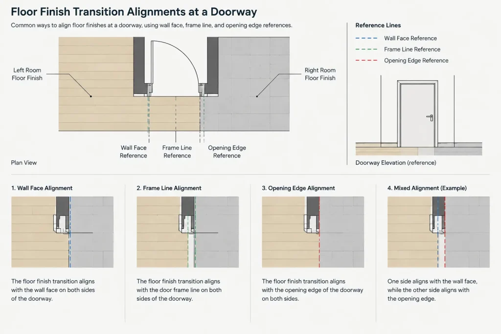
A doorway is a common location for a floor finish change, but the door opening alone does not define the transition. The drawing should establish the intended alignment using a clear architectural reference.
Possible controlling references include a frame line, wall face, opening edge, cabinet face, step edge, or another documented construction line. The appropriate choice depends on the assembly and design intent. The key is consistency and clarity rather than relying on a presumed universal location.
Review transitions at:
- Doors between rooms with different finishes
- Openings without doors
- Corridor intersections and alcoves
- Kitchen and service areas
- Restroom entrances and fixture zones
- Changes around reception desks or built-ins
- Stair landings and elevator entrances
- Vestibules and exterior thresholds
- Changes in floor elevation or substrate condition
If a transition requires a specific profile, trim piece, divider, or installation detail, reference the relevant detail or specification information rather than attempting to communicate the entire assembly with a single plan line.
Choose a clear graphic hierarchy
Finish information should be visible without competing with walls, doors, and other primary plan elements. Boundary lines are usually subordinate to cut walls but must remain distinct from incidental joints, furniture, or hatch edges.
Use a consistent hierarchy among:
- Architectural base linework
- Finish boundaries
- Finish hatch patterns
- Transition indicators
- Finish tags and keynotes
Evaluate the drawing at its intended plotted scale. A hatch that looks subtle while zoomed in may merge into a dark mass on a sheet. Conversely, a pattern that is spaced too broadly may disappear from a small finish region.
Where many materials occur in a compact area, a finish code and boundary may communicate more clearly than a dense hatch. Hatching, tagging, and notes should support one another rather than repeat the same information with equal visual emphasis.
Coordinate tags, legends, and schedules
A finish tag should identify a defined region and connect to a controlled legend or schedule. Avoid free-form abbreviations that appear only on the plan and cannot be interpreted elsewhere in the drawing set.
Depending on the project documentation method, a floor finish identifier may relate to a room finish schedule, material legend, keynote, or finish specification. Whichever method is used, maintain one consistent identifier for the same finish.
| Drawing element | Primary purpose | Coordination check |
|---|---|---|
| Finish boundary | Defines the material extent | Does it close cleanly and follow the intended construction alignment? |
| Finish tag | Identifies the material or system | Does its code match the legend or schedule? |
| Hatch or pattern | Visually distinguishes regions | Is it legible without obscuring the base plan? |
| Transition symbol | Calls attention to a material change | Is its location and reference clear? |
| Room finish schedule | Summarizes finishes by room | Does it agree with exceptions shown graphically? |
Room schedules may describe a general floor finish while the plan shows local exceptions, borders, inserts, or zones. Make those exceptions explicit. A reviewer should not have to guess whether the plan or schedule takes precedence.
Handle partial-room and patterned layouts carefully
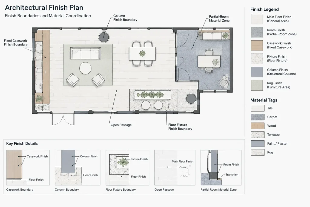
Not every room has one uniform finish. Open-plan areas, lobbies, retail interiors, and common spaces may contain multiple zones without walls separating them. In these cases, the finish boundary itself becomes an important layout control.
Use identifiable architectural references to locate the geometry. A finish zone might align with a column grid, storefront, ceiling feature, casework edge, circulation path, or another designed element. If the alignment cannot be inferred reliably from the plan, add appropriate dimensions or a referenced enlarged drawing.
Decorative borders, bands, and directional patterns also require coordination beyond a generic material hatch. The drawing may need to establish orientation, centerlines, alignment points, or the relationship to room geometry. Avoid creating a visually elaborate CAD pattern that does not communicate how the installer should locate it.
Account for objects that interrupt or cover the floor
Determine whether finish graphics should run beneath fixed objects or stop at their perimeter. The answer depends on design intent, installation sequencing, object permanence, and the level of documentation required.
Review areas beneath or around:
- Fixed casework and millwork
- Built-in seating
- Equipment bases and housekeeping pads
- Plumbing fixtures
- Raised platforms and stages
- Floor grilles, mats, drains, and access panels
- Columns and freestanding structural elements
The CAD graphic should not imply an installation condition that has not been confirmed. Where the plan cannot adequately describe the interface, coordinate it through details, notes, schedules, or specifications.
Use hatches without making them fragile
Complex associative hatches can become unstable when they depend on a large number of referenced edges. For frequently revised plans, a controlled polyline boundary may be more reliable than a hatch generated directly from every surrounding wall and object.
Organize separate finish regions so that one edit does not unexpectedly alter distant areas. Check islands and openings within hatch regions, particularly around columns, shafts, and built-ins. Remove duplicate hatch objects and verify that stacked solid fills are not hiding important linework.
If performance becomes poor, review the complexity and scale of the pattern before breaking the drawing into uncontrolled fragments. The goal is editable finish information, not simply a correct appearance in one viewport.
Coordinate finish plans with related drawings
Floor finish boundaries can conflict with several other parts of the architectural set. Compare them with:
- Dimensioned floor plans for current wall and opening locations
- Door plans and schedules for frame and threshold conditions
- Interior elevations for base, casework, and material relationships
- Enlarged plans for detailed room layouts
- Reflected ceiling plans where floor and ceiling geometry intentionally align
- Sections and details at level changes or special transitions
- Demolition plans for retained and removed finishes
- Room finish schedules and material legends
Do not treat visual alignment between floor and ceiling features as intentional unless the design confirms it. Similar-looking geometry in different drawing types may be unrelated.
Quality-control checklist
Before issuing the finish plan, complete a focused review rather than checking only whether every room has a tag.
- Confirm that finish boundaries match the current architectural base.
- Check that every intended finish region is closed and identifiable.
- Look for narrow gaps, overlaps, and accidental slivers between regions.
- Verify transitions at doors, open passages, and level changes.
- Compare all finish identifiers with the legend and room finish schedule.
- Review partial-room zones and local exceptions for clear extent.
- Confirm that hatches do not conceal doors, fixtures, dimensions, or notes.
- Check fixed casework, equipment, columns, and floor openings.
- Inspect the plan at the actual sheet scale and in the plotted output.
- Verify that referenced details and enlarged plans use current callouts.
A strong finish plan is not defined by the number of hatch patterns it contains. Its value comes from clear extents, intentional transition locations, controlled identifiers, and agreement with the rest of the architectural drawing set.
A decision hierarchy for ambiguous finish boundaries
When the location of a finish change is unclear, resolve the design intent before refining the hatch. Begin with the architectural element that controls the transition, then confirm the material extent, transition condition, and identifying information. This prevents graphic appearance from becoming a substitute for an actual coordination decision.
A useful review sequence is:
- Controlling geometry: Identify the wall face, opening, frame, casework edge, platform, or other element that establishes the location.
- Material extent: Confirm which finish belongs on each side and whether the finish continues beneath fixed objects.
- Transition condition: Determine whether the interface needs a symbol, note, detail reference, or other documentation.
- Identification: Check that each resulting region has an unambiguous connection to the applicable legend or schedule.
- Graphic presentation: Apply boundaries, patterns, and tags so they remain readable without overpowering the base plan.
Manage revisions by checking interfaces
Finish-plan revisions are often concentrated at interfaces rather than in the middle of a material field. After an architectural base update, review moved doors, altered wall openings, revised casework, shifted equipment, and changed floor features before assuming that existing finish regions remain valid.
It is also helpful to distinguish a geometry correction from a design change. Closing a small drafting gap may preserve the intended finish extent, while moving a transition to a different wall face changes the documented installation intent. Keeping that distinction clear supports more focused review and reduces accidental changes during cleanup.
Review the plotted communication, not only the CAD objects
A technically closed boundary can still produce an unclear drawing. Conduct a final visual review with the architectural base, finish graphics, identifiers, and transition information shown together. Confirm that every visible material change can be understood without selecting objects or inspecting layer properties.
Where the finish plan cannot fully explain a condition, use coordinated details, schedules, notes, or enlarged drawings. The plan should direct the reader to the necessary information rather than imply precision that the drawing does not actually provide.
Frequently asked questions
Should floor finish boundaries be drawn as closed polylines?
Closed, controlled geometry is generally easier to select, hatch, inspect, and revise than a collection of unrelated line segments. The chosen method should still follow the project CAD standards and remain understandable to other team members.
Where should a floor finish transition occur at a doorway?
There is no single location that applies to every doorway. The transition should align with a clearly identified construction reference, such as a frame line, wall face, or opening edge, based on the intended assembly and project documentation.
Should finish hatches be generated directly from wall geometry?
Directly dependent hatches may become difficult to maintain when the surrounding plan changes or contains complex referenced geometry. A controlled finish boundary can provide a more deliberate and reviewable basis for the hatch.
Do floor finishes continue beneath fixed casework?
That depends on the design intent, installation sequence, object permanence, and documentation requirements. The CAD drawing should not assume continuation or termination without confirmation from the project information.
How should a partial-room finish zone be located?
Relate the zone to identifiable architectural geometry. If its position cannot be understood reliably from the plan, support it with appropriate dimensions, notes, alignment information, or a referenced enlarged drawing.
What should be checked after the architectural base changes?
Review finish interfaces near revised walls, doors, openings, casework, equipment, columns, level changes, and fixed floor features. Also confirm that tags, schedules, transition references, and hatch extents still agree.