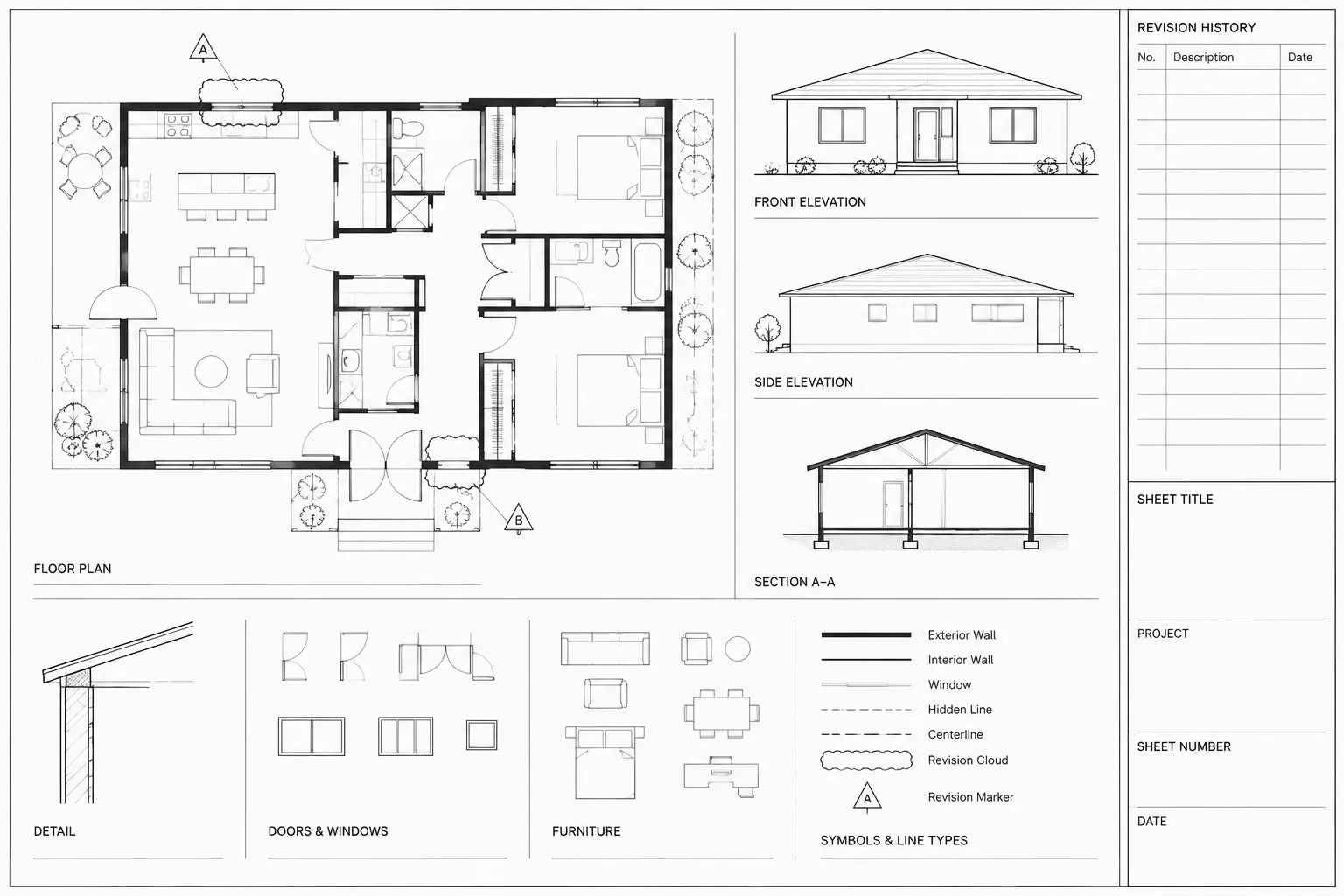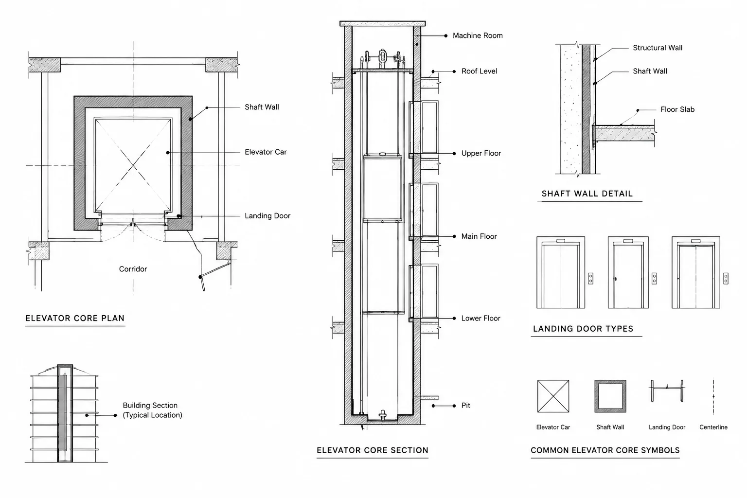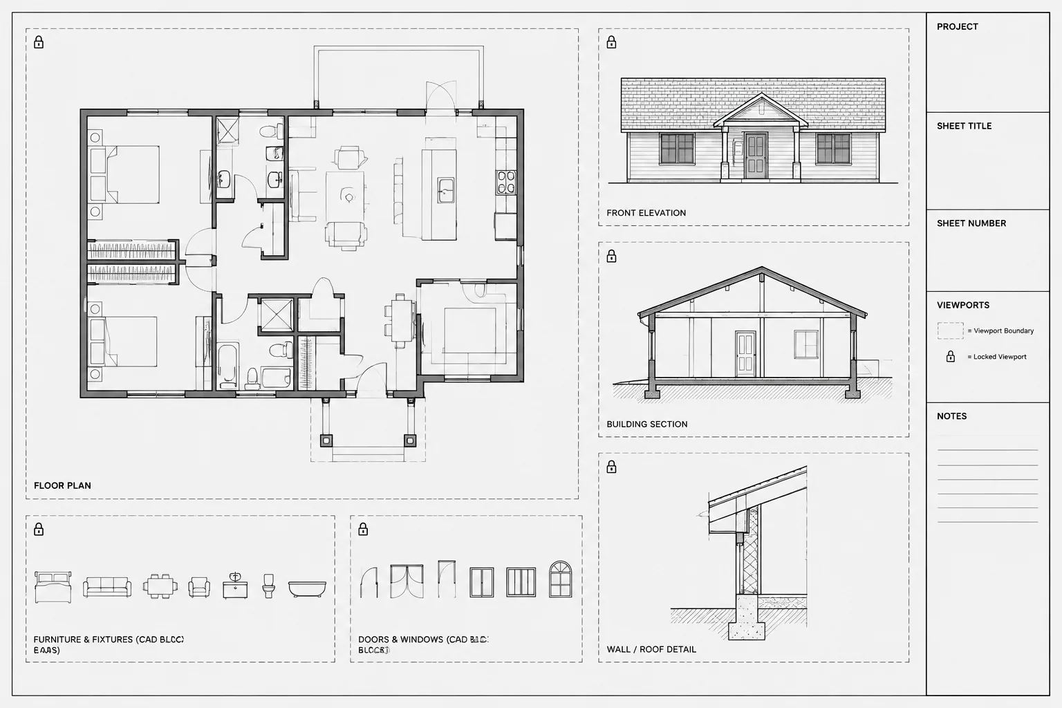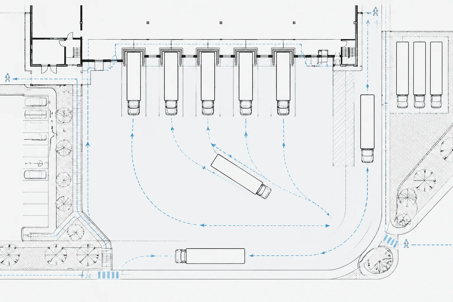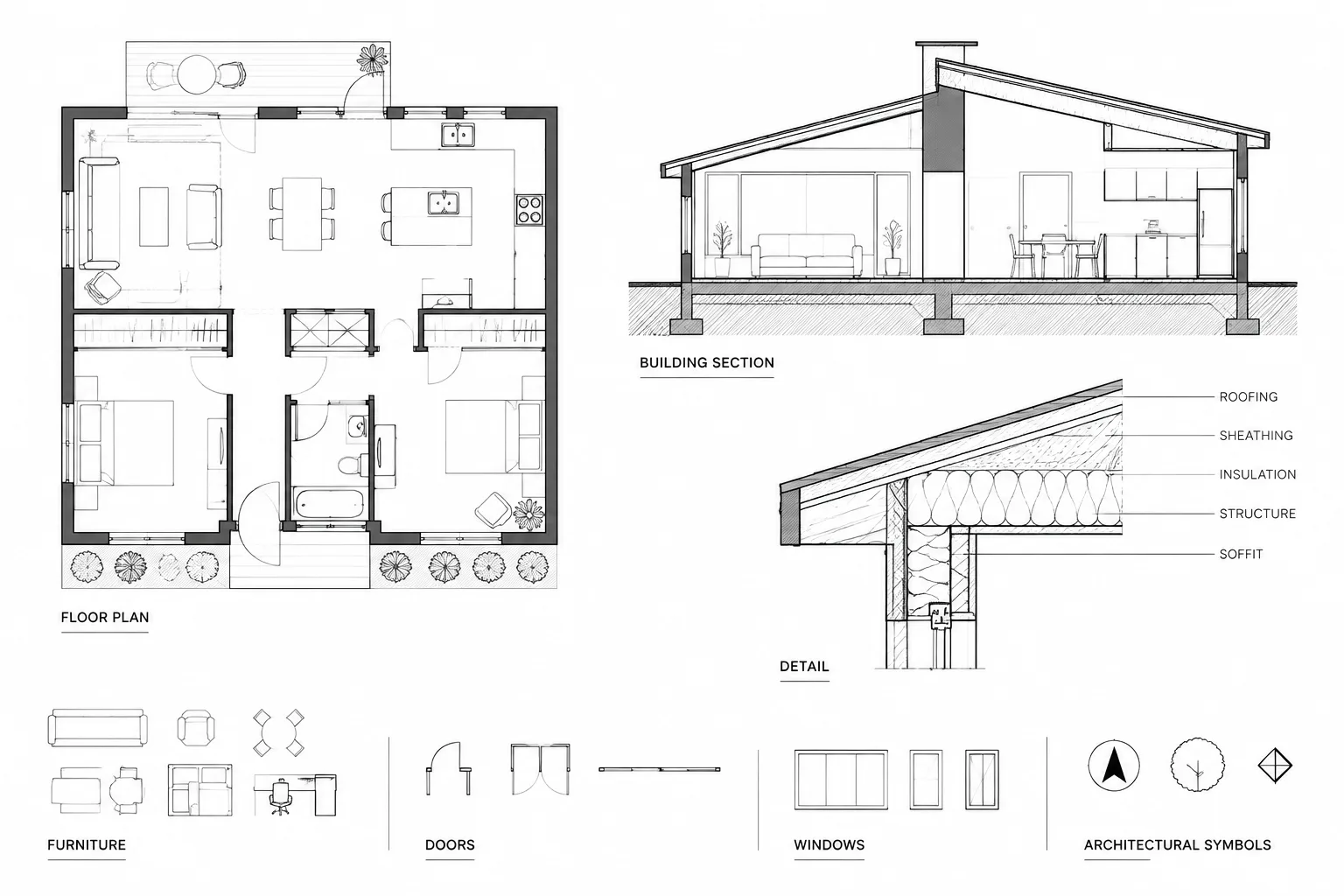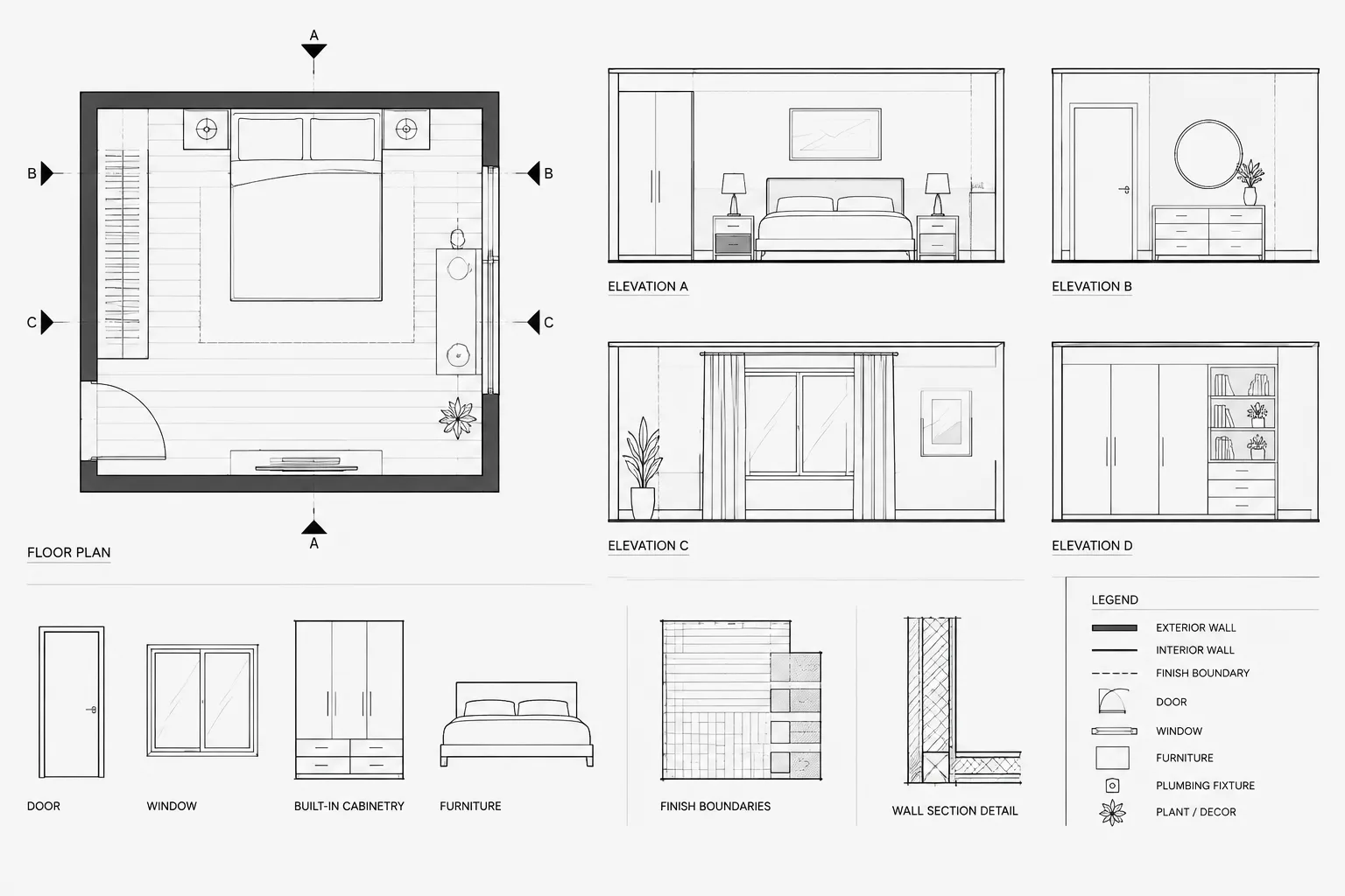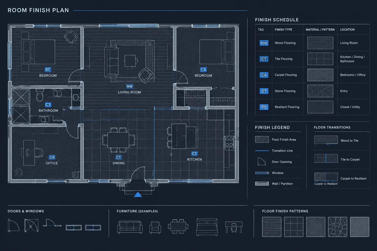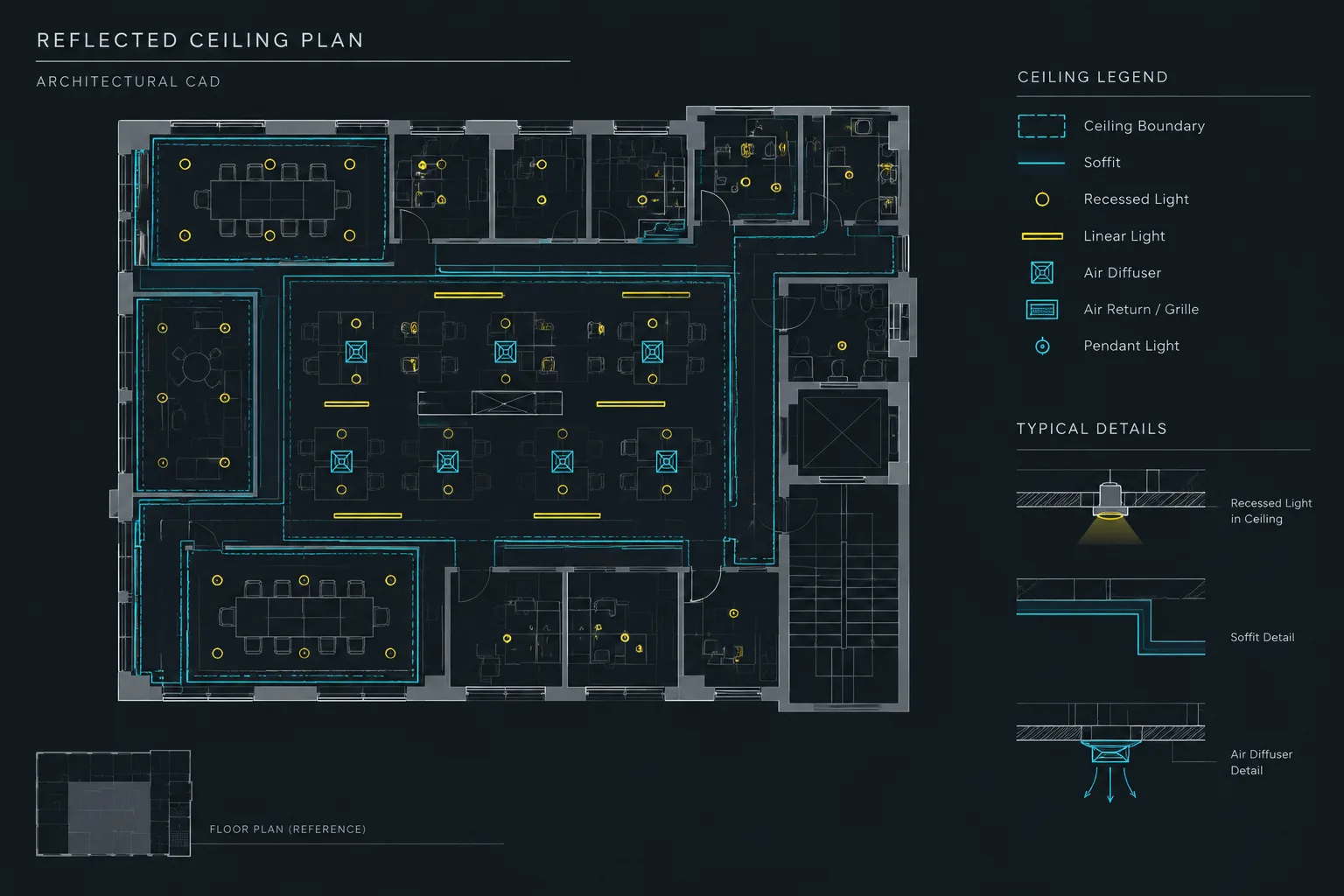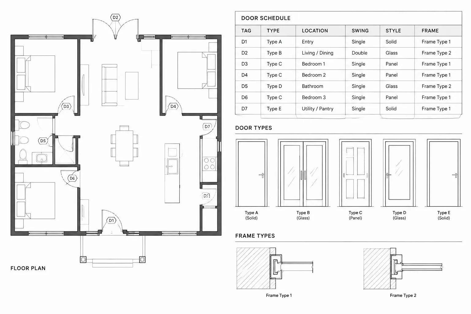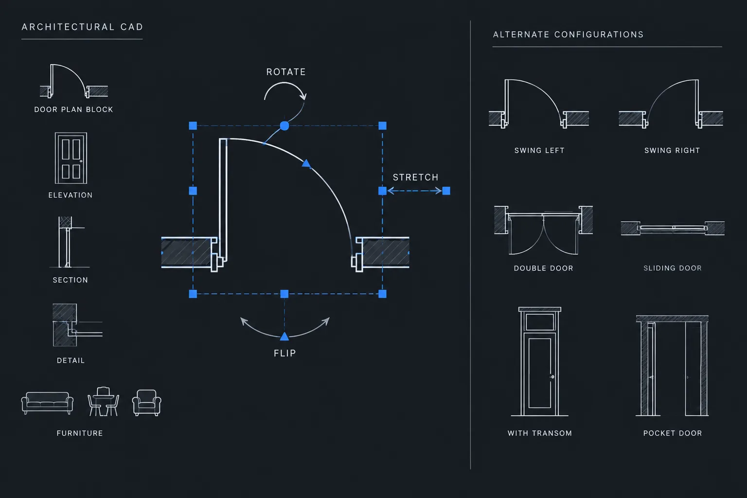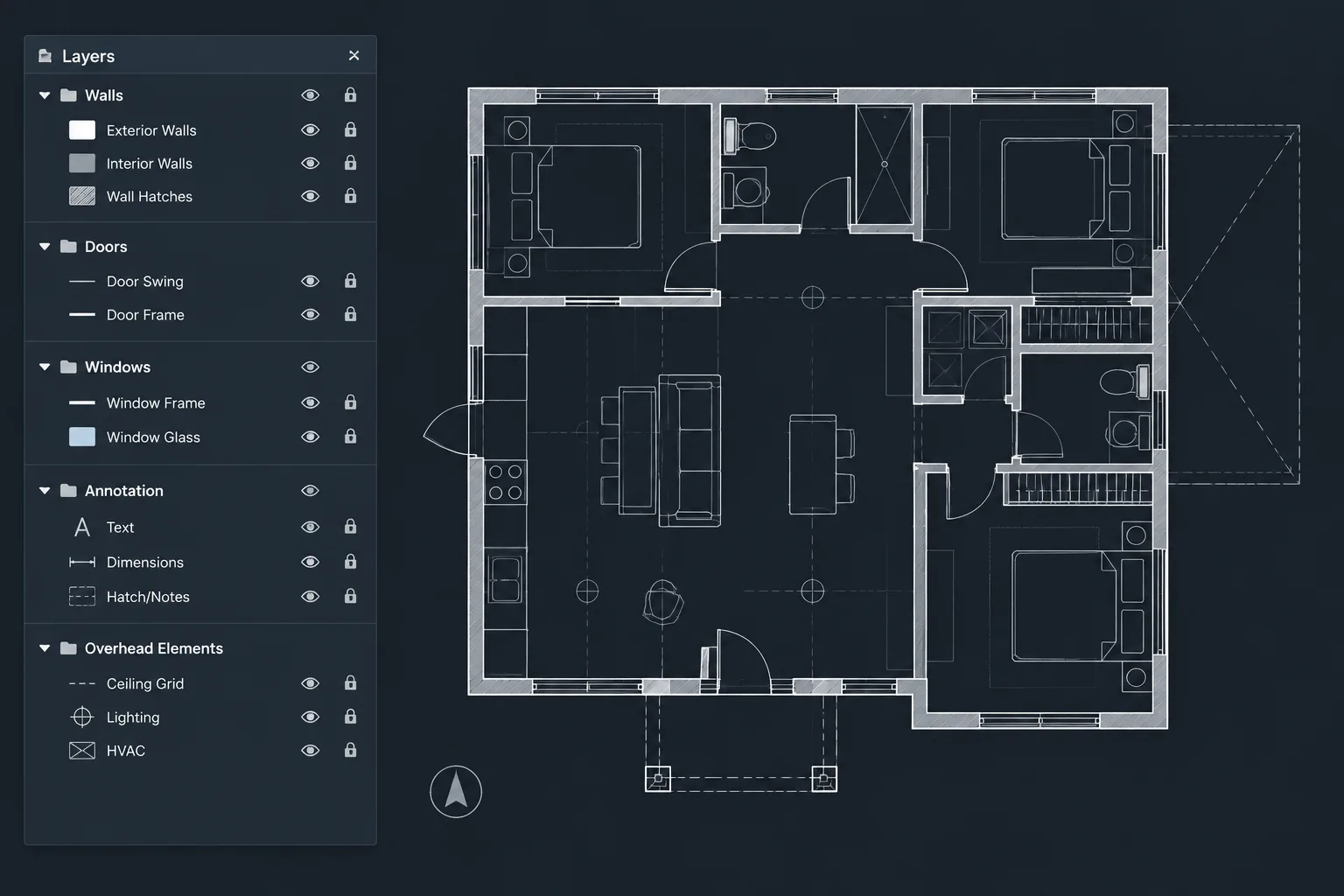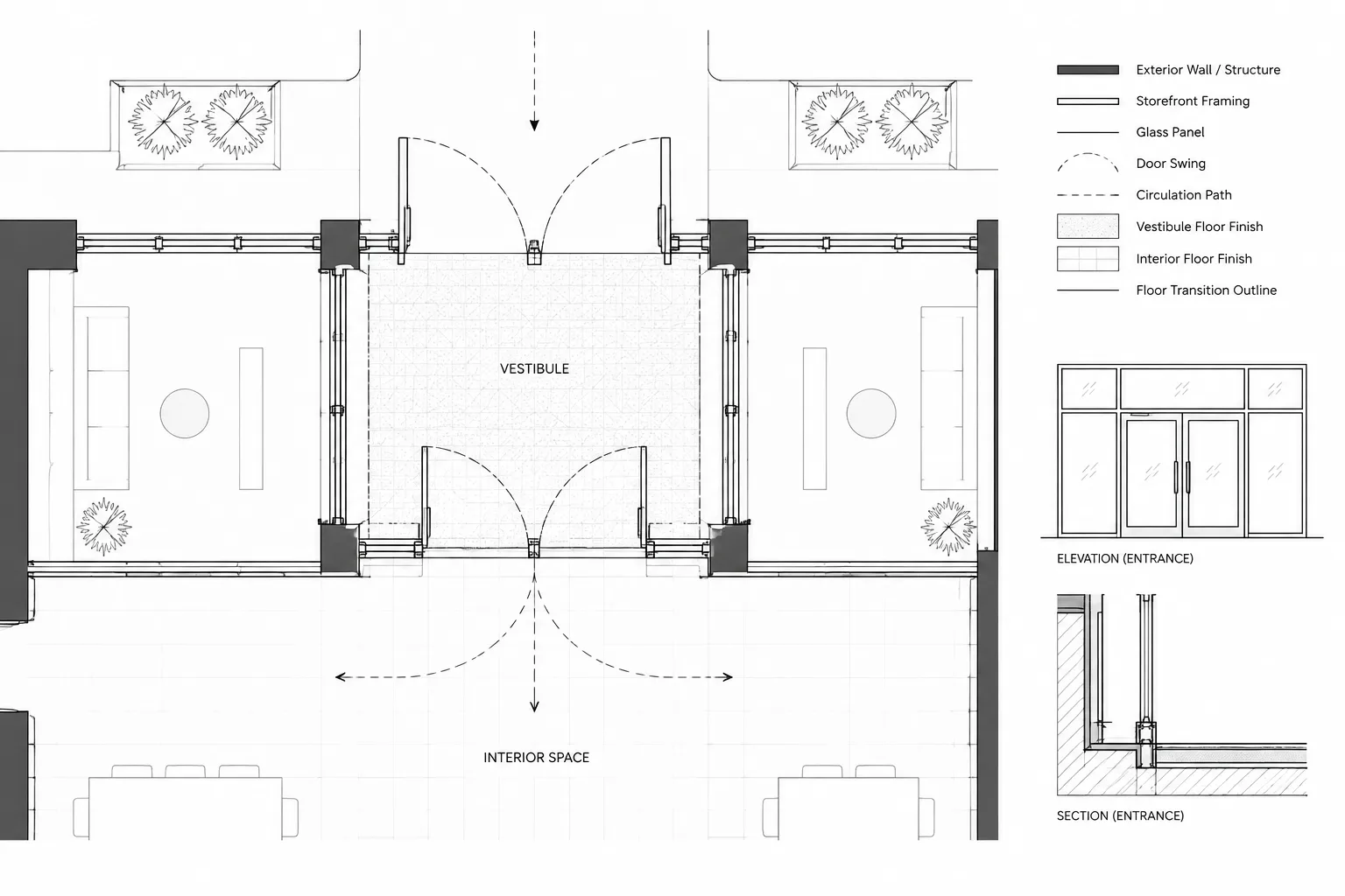
Building entrance and vestibule drawings require close coordination because circulation, enclosure, security, finishes, and overhead systems converge in a limited area. A change to a door position or frame line can affect the floor plan, reflected ceiling plan, elevations, sections, schedules, and adjacent site work.
This guide explains a practical building entrance vestibule CAD workflow focused on shared reference geometry, clear drawing relationships, and disciplined quality control. It is intended to help architects and drafters identify conflicts early while keeping the entrance consistent throughout the architectural drawing set.
A building entrance may occupy a small portion of a floor plan, but it concentrates many architectural decisions in one location. Exterior and interior doors, storefront framing, floor finishes, weather protection, security devices, accessible routes, structural supports, lighting, drainage, and signage may all meet within a compact area.
Because these elements are often developed in separate drawings, entrance problems can remain hidden until late coordination or construction. A reliable building entrance vestibule CAD workflow treats the entrance as a coordinated three-dimensional zone rather than a pair of door symbols placed in plan.
Begin with the entrance sequence
Before adding detail, identify how people and materials move through the entrance. Trace the route from the exterior approach to the interior circulation space. A typical sequence may include a sidewalk or landing, an exterior door, a vestibule, an interior door, and a lobby or corridor.
Ask practical questions while reviewing the sequence:
- Which direction does each door swing, and where does the leaf rest when open?
- Can both door sets operate without conflicting with each other?
- Does the entrance align with the exterior path and the intended interior destination?
- Are fixed glazing, columns, furniture, or equipment reducing the usable circulation zone?
- Where do floor materials, ceiling systems, and environmental boundaries change?
- How are deliveries, carts, and maintenance activities expected to pass through the space?
Do not assume that a visually centered entrance is automatically functional. The circulation route may need to respond to a reception desk, security checkpoint, elevator lobby, or exterior drop-off rather than the centerline of the facade.
Establish a dependable CAD background
Coordinate the entrance against current architectural, structural, civil, and consultant backgrounds. Confirm that referenced files use the correct units, insertion point, orientation, and elevation datum before drawing detailed geometry.
Useful entrance-related layers or layer groups commonly include walls, doors, glazing, overhead elements, floor transitions, casework, equipment, annotations, and clearance graphics. Project layer names should follow the established office or project convention rather than a separate entrance-only system.
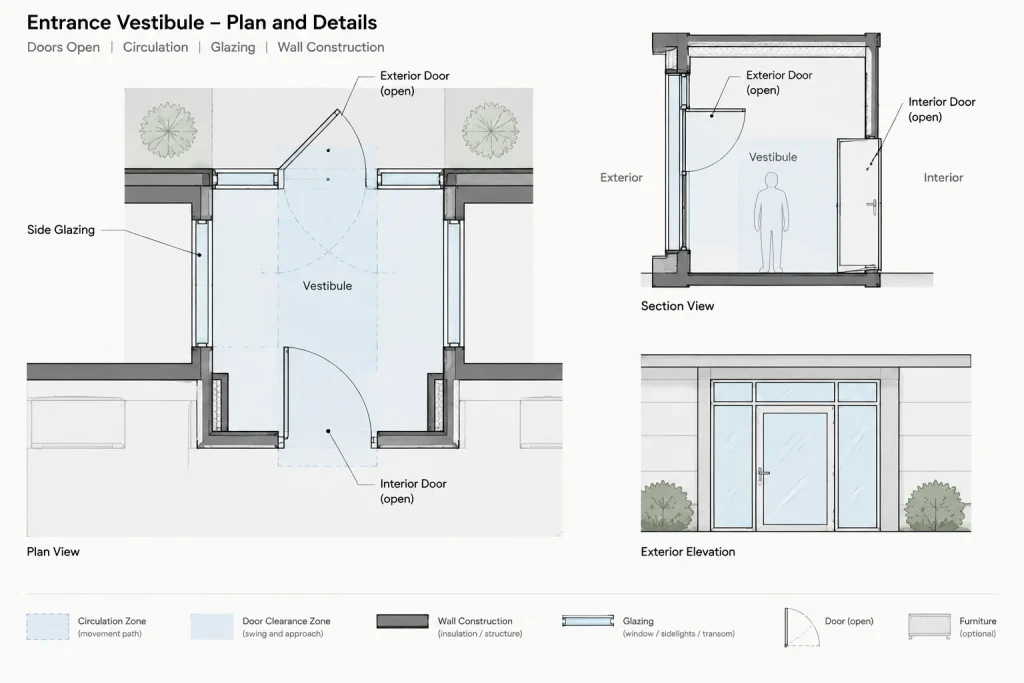
Keep temporary analysis graphics distinct from construction geometry. Door movement envelopes, circulation paths, and review clouds can be placed on non-plotting or clearly controlled coordination layers. This makes them easy to display during review without allowing them to appear accidentally in issued sheets.
Draft the walls, frames, and glazing as coordinated assemblies
Start with the primary wall and frame geometry instead of inserting door blocks into an approximate opening. Determine where the exterior wall line, vestibule partitions, storefront or curtain-wall framing, and interior finishes meet.
Show frame depth and adjacent construction accurately enough for the drawing scale. A single-line frame may be suitable for a general plan, while an enlarged entrance plan may need jambs, mullions, finish returns, and frame offsets. Avoid adding detail that cannot remain legible at the plotted scale.
Where doors occur in glazed assemblies, coordinate door frames with surrounding mullions and panels. Check whether a door centerline, rough opening, frame edge, or glazing module controls the layout. Mixing these reference points is a common cause of small but persistent misalignments between plans and elevations.
Coordinate both sets of doors
Vestibule door coordination should include more than leaf width and swing direction. Draw each leaf in its intended closed position and represent the swing consistently with the project drafting convention. Then review the doors in their open positions.
Look for conflicts between:
- Exterior and interior door swings
- Door leaves and sidelights or projecting mullions
- Pulls, panic hardware, or operators and adjacent surfaces
- Open doors and circulation through the vestibule
- Doors and floor mats, grilles, drains, or recessed systems
- Doors and security pedestals, card readers, intercoms, or reception functions
Use manufacturer information and project requirements when representing hardware or operating equipment. Generic CAD blocks are useful for planning, but they should not be treated as verified product geometry.
Review clearances as zones, not isolated dimensions
Entrance clearances are easier to evaluate when shown as graphic zones. These may represent door operation, approach space, accessible circulation, queuing, or maintenance access. Keep such zones on a dedicated coordination layer and label their purpose when several overlap.
Applicable dimensions depend on the adopted regulations, occupancy, door type, hardware, and project conditions. Verify required clearances with the responsible design professional and current governing criteria rather than relying on a downloaded block or a previous project.
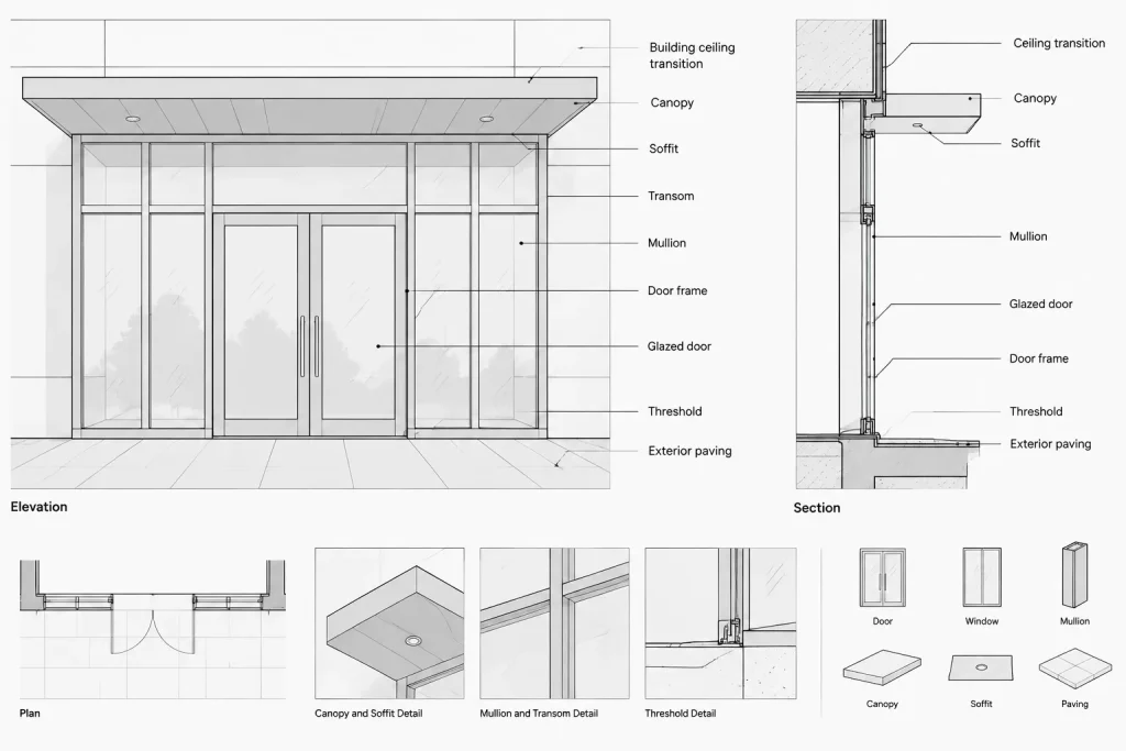
Also check vertical conditions. A plan may appear clear while an overhead closer, operator, light fixture, sign, canopy support, or low soffit creates a conflict in elevation.
Coordinate floor levels and transitions
An entrance often connects exterior paving, a threshold, vestibule flooring, and an interior finish. Establish the relevant finish-floor elevations and slopes before finalizing door and frame details.
Identify where material changes occur and what controls each transition. The change might align with a door centerline, frame face, threshold edge, vestibule wall, or floor recess. Use one intentional control point and carry it consistently through the floor plan, finish plan, enlarged plan, and details.
Review recessed mats, grilles, drains, and floor boxes with the structural system below. Their outlines should not be added as decorative symbols without checking depth, support, access, and adjacent construction. Exterior drainage and paving slopes should also be coordinated so water is directed appropriately rather than toward the entrance.
Connect the floor plan to the RCP and elevations
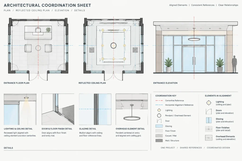
The vestibule ceiling plan should be developed from the same geometry as the floor plan. Project wall faces, frame lines, and major centerlines rather than redrawing the room by eye. Coordinate ceiling breaks, soffits, lighting, sensors, sprinklers, diffusers, access panels, and door operators with the narrow space available.
Exterior and interior elevations should confirm:
- Door and glazing alignment
- Head heights and transom organization
- Mullion continuity
- Canopy, soffit, and ceiling relationships
- Signage and security-device locations
- Finish extents and material transitions
If the entrance changes in plan, update the related elevations and sections in the same work session. Entrance discrepancies often result from editing one view while leaving other views untouched.
Use an enlarged entrance plan when needed
A general floor plan may not have enough space for the notes and dimensions required at a complex entrance. An enlarged plan can clarify door relationships, framing, finishes, security equipment, and floor features without overcrowding the overall plan.
The enlarged view should remain traceable to the primary plan. Use consistent grids, wall references, room identifiers, door numbers, and detail callouts. Avoid creating independent duplicate geometry unless the project workflow includes a dependable method for keeping it synchronized.
| Drawing view | Primary coordination purpose | Items to verify |
|---|---|---|
| Floor plan | Overall location and circulation | Walls, doors, approach, adjacent rooms |
| Enlarged plan | Detailed entrance layout | Frames, hardware zones, floor features, dimensions |
| Reflected ceiling plan | Overhead coordination | Ceilings, lighting, devices, operators, soffits |
| Elevation | Vertical composition | Glazing modules, heads, signs, finishes |
| Section or detail | Construction relationships | Thresholds, floor levels, enclosure, canopy interface |
Dimension from stable references
Entrance dimensions should communicate design intent without creating competing control points. Use stable references such as grids, structural faces, primary wall faces, or established frame lines. Avoid dimensioning the same element from unrelated origins in different drawings.
Choose whether a dimension controls an opening, frame, mullion, wall face, or centerline, and make that choice visually clear. Coordinate critical dimensions across the plan, elevation, schedule, and details. If a frame profile or product selection is not final, distinguish design intent from product-dependent information.
Run a focused entrance quality-control review
Perform a dedicated review after updating the entrance rather than relying only on a general drawing check. Freeze or isolate unrelated layers if necessary so conflicts are easier to see.
Plan review
- Confirm both door sets are present, tagged, and scheduled.
- Review door swings and circulation with leaves shown open.
- Check glazing, mullions, walls, and structural elements for alignment.
- Verify floor transitions and recessed features.
- Inspect nearby furniture, security equipment, and signage.
Vertical review
- Compare plan geometry with exterior and interior elevations.
- Check ceiling, soffit, canopy, and frame-head relationships.
- Confirm that overhead devices do not conflict with doors or glazing.
- Review thresholds, floor levels, paving, and drainage in section.
Sheet review
- Confirm callouts lead to the correct enlarged views and details.
- Check that door numbers match the schedule.
- Remove duplicate or contradictory dimensions.
- Plot a test sheet to review lineweights, swing graphics, hatches, and note readability.
Treat the entrance as a coordination package
The most dependable entrance drawings are produced by coordinating a small package of related views rather than completing each sheet independently. Plans establish movement and location; reflected ceiling plans resolve overhead systems; elevations organize frames and finishes; sections explain levels and enclosure conditions; schedules carry door and glazing information.
When these views share stable references and are reviewed together, the entrance becomes easier to document, revise, and construct. The goal is not simply a clean vestibule plan, but a consistent entrance solution across the entire architectural drawing set.
Manage entrance revisions across the drawing set
Entrance coordination should continue after the initial layout is approved. Product information, security requirements, structural conditions, finish selections, and consultant updates can all change the documented solution. When a revision occurs, identify every affected view before editing so the change is not confined to a single plan.
A useful revision review follows the entrance geometry through the floor plan, enlarged plan, reflected ceiling plan, elevations, sections, schedules, and details. It should also include consultant drawings that rely on door, frame, ceiling, paving, drainage, lighting, or device locations.
Separate design controls from product-dependent geometry
Stable design controls may include grids, primary wall faces, structural references, frame lines, finish-floor relationships, and circulation paths. Product-dependent geometry may include hardware profiles, operators, thresholds, framing components, and security devices. Keeping this distinction clear helps the team revise selected products without unintentionally changing the architectural layout.
Generic symbols should remain visibly generic until verified information is available. Once product data is incorporated, review its relationship to adjacent construction rather than replacing a block and assuming the coordination is complete.
Keep annotations connected to intent
Entrance notes and dimensions should explain what controls the work. Avoid annotations that describe an element without identifying its relationship to a wall, frame, finish transition, or established reference. Where several disciplines share the same location, use clear terminology so similar-looking centerlines and edges are not mistaken for one another.
Before issue, compare tags, schedules, callouts, and detail references with the visible geometry. A well-drafted entrance can still create confusion if its identifiers or referenced details point to outdated information.
Use the entrance as a drawing-set consistency check
Because an entrance touches many systems, it is a useful test of overall drawing coordination. Misaligned frame lines, inconsistent finish boundaries, unresolved overhead devices, or conflicting door information often indicate that related views are being developed independently.
A coordinated entrance package should communicate the same spatial and construction intent from every view. Final suitability still depends on project-specific requirements, verified product information, governing criteria, and review by the responsible design professionals.
Frequently asked questions
What should be drawn first when drafting a vestibule?
Begin with the controlling wall, frame, glazing, and circulation geometry. Door blocks should be placed only after the opening and adjacent assemblies have dependable reference lines.
Why should door swings be reviewed in the open position?
The open position reveals conflicts that may not be visible when the leaves are shown closed. These can involve the opposite door set, glazing, hardware, security devices, floor features, furniture, and the intended path through the vestibule.
When is an enlarged entrance plan useful?
An enlarged plan is useful when the general floor plan cannot clearly show framing, hardware zones, floor transitions, equipment, dimensions, and detail references. The enlarged view should remain tied to the same source geometry and stable references as the primary plan.
How should clearance graphics be handled in CAD?
Place door movement, circulation, approach, and maintenance zones on controlled coordination layers. Label their purpose where necessary, and prevent temporary analysis graphics from appearing unintentionally on issued sheets.
Which drawings should be checked after an entrance changes?
Review the floor plan, enlarged plan, reflected ceiling plan, elevations, sections, schedules, details, and affected consultant backgrounds. Also check tags, dimensions, callouts, finish boundaries, and overhead elements.
Can a generic entrance CAD block be used as a final detail?
A generic block can support early planning, but it does not verify a selected frame, hardware set, operator, threshold, security device, or construction interface. Final documentation should be coordinated with current project requirements and verified product information.