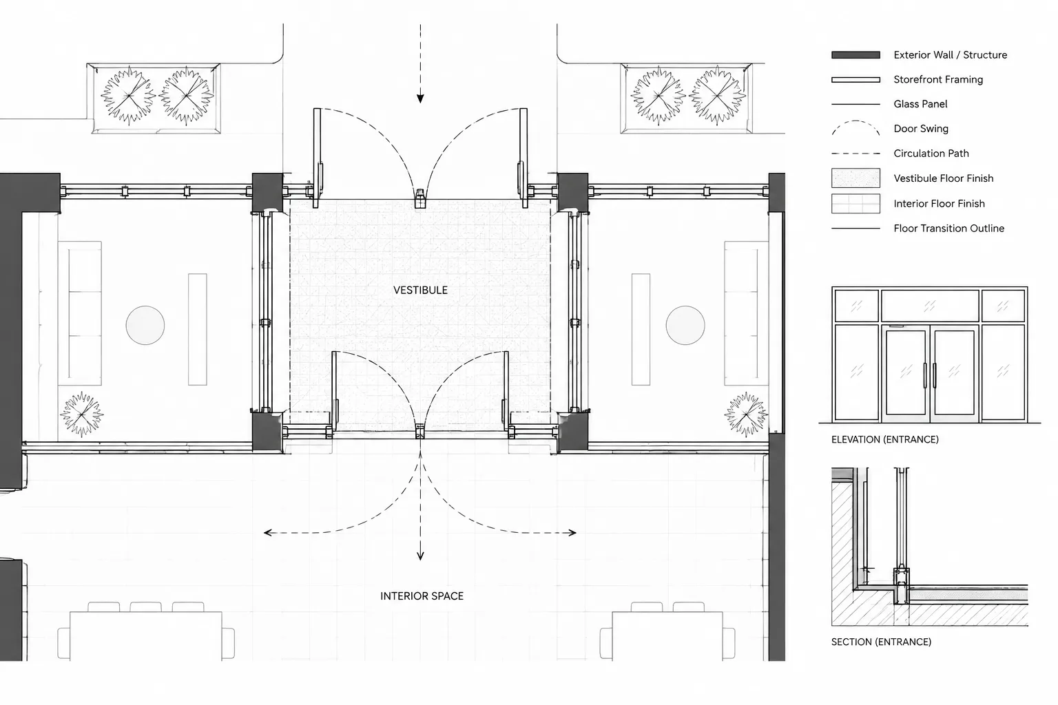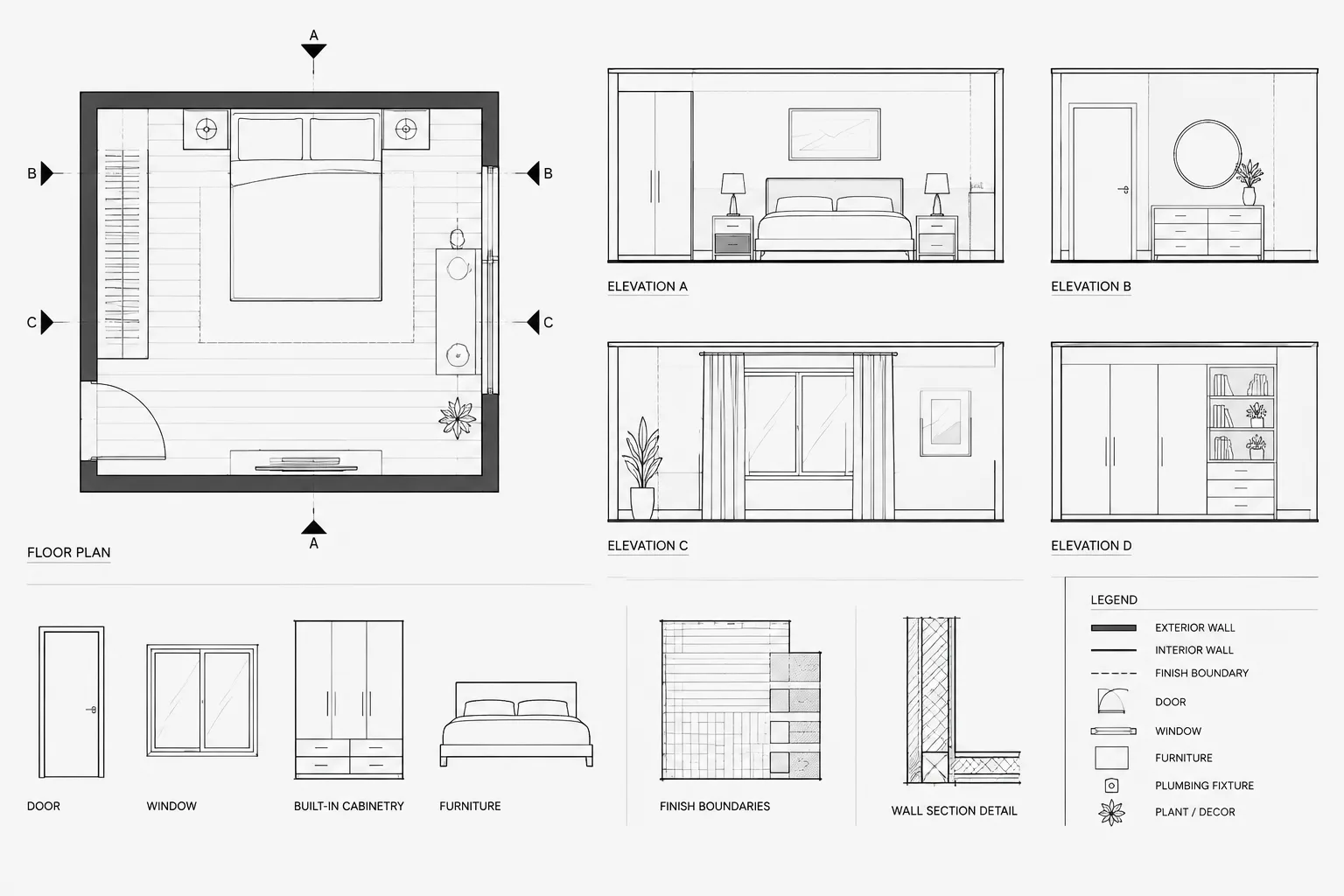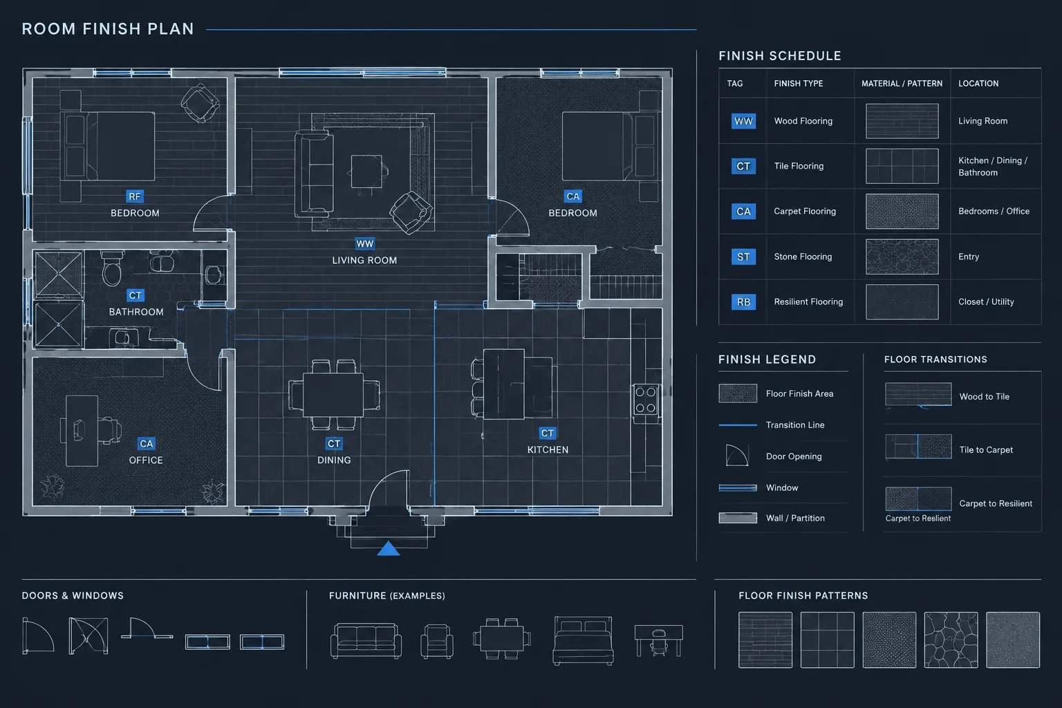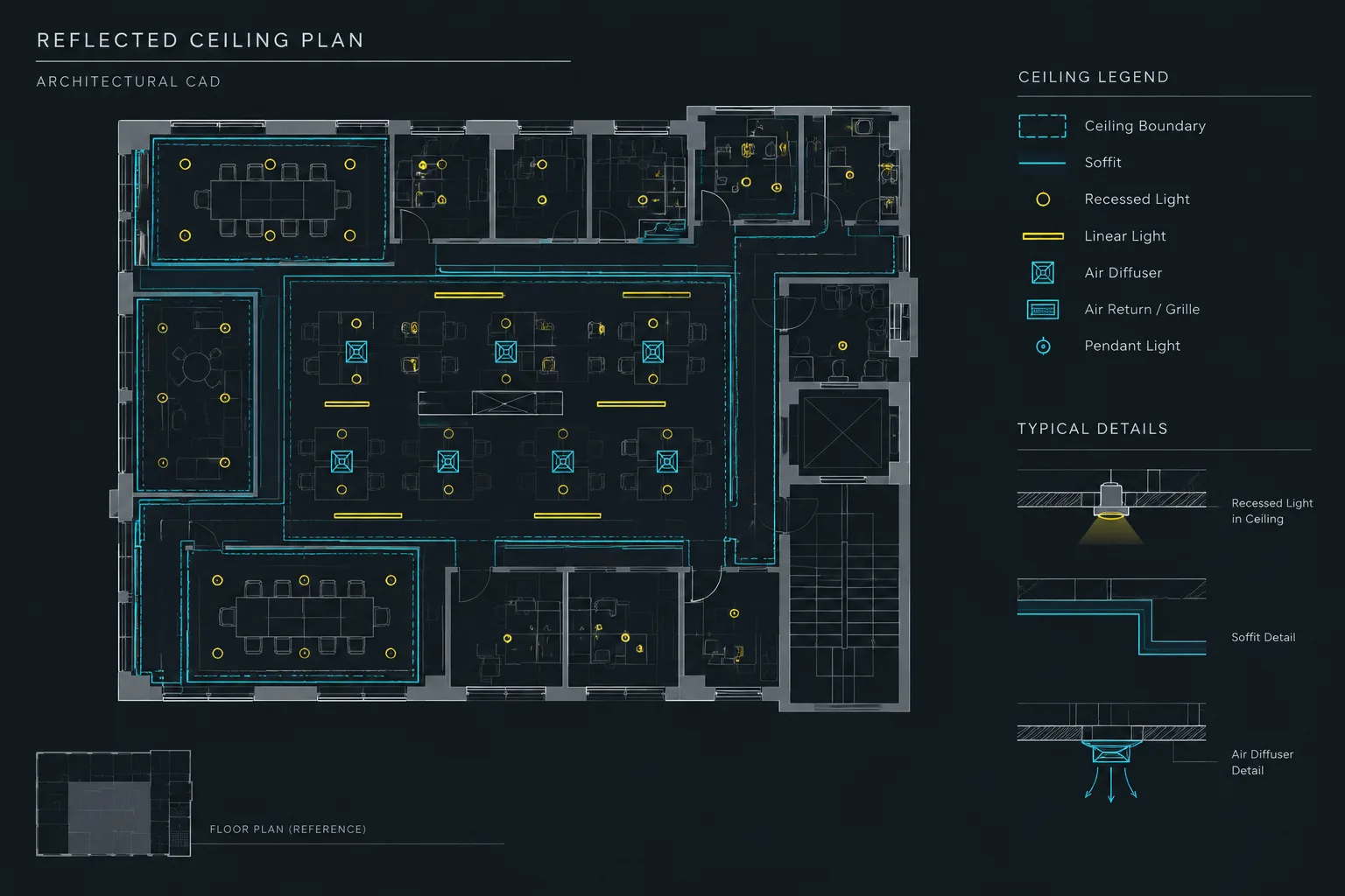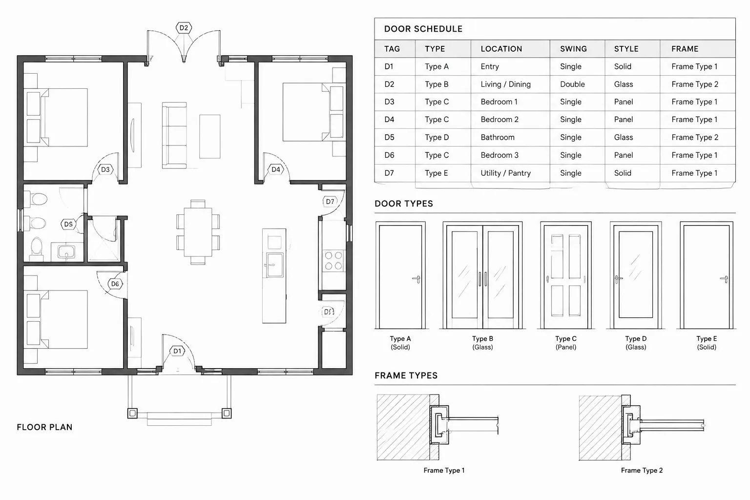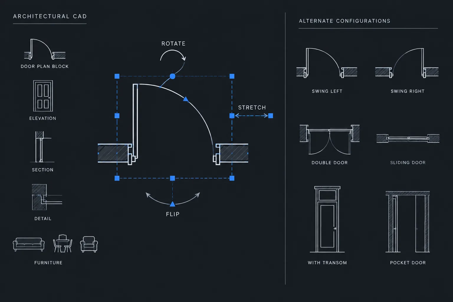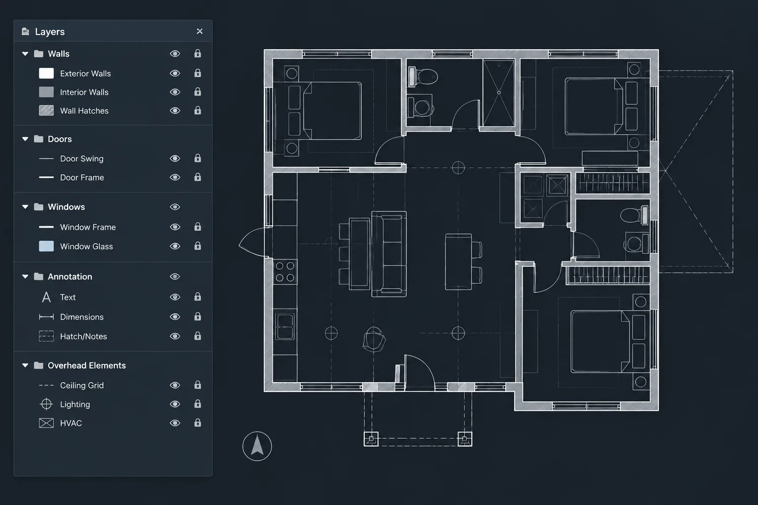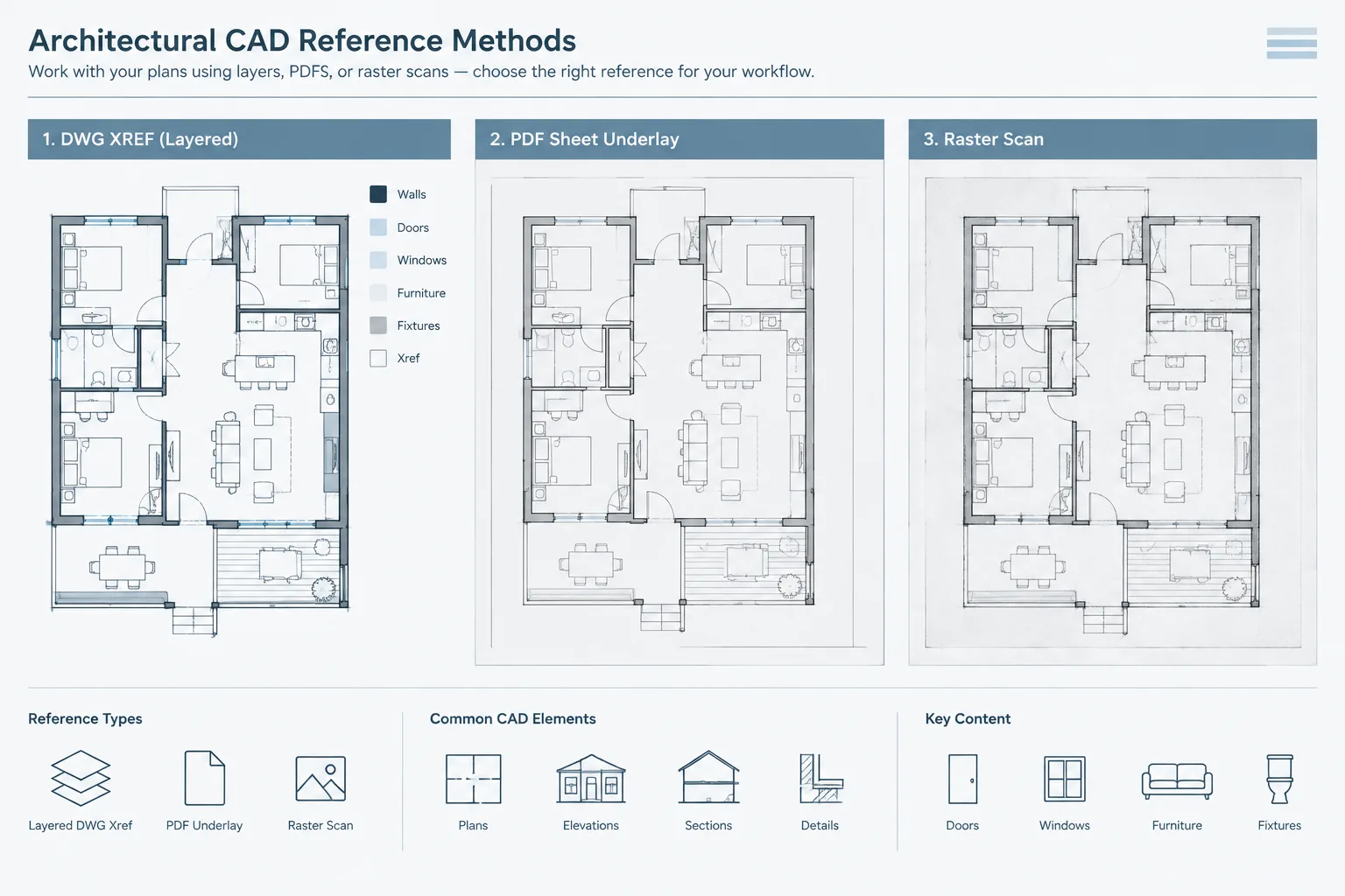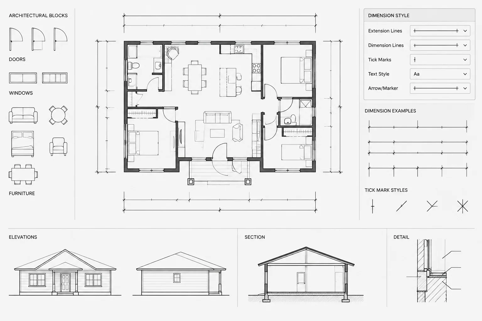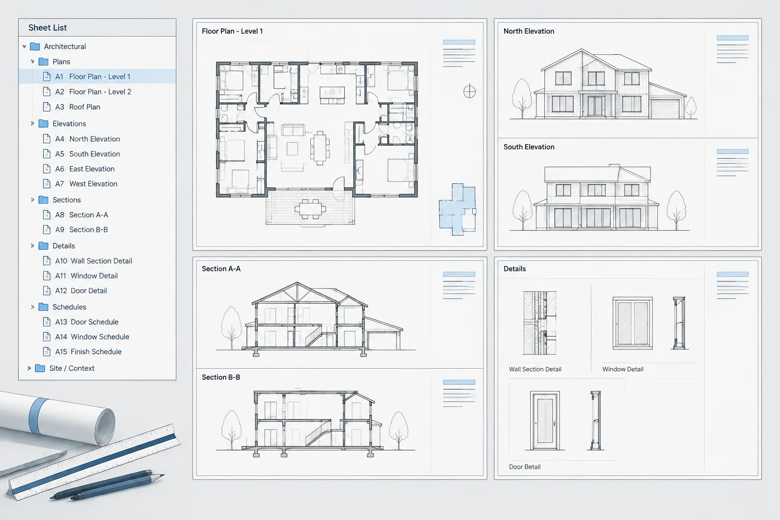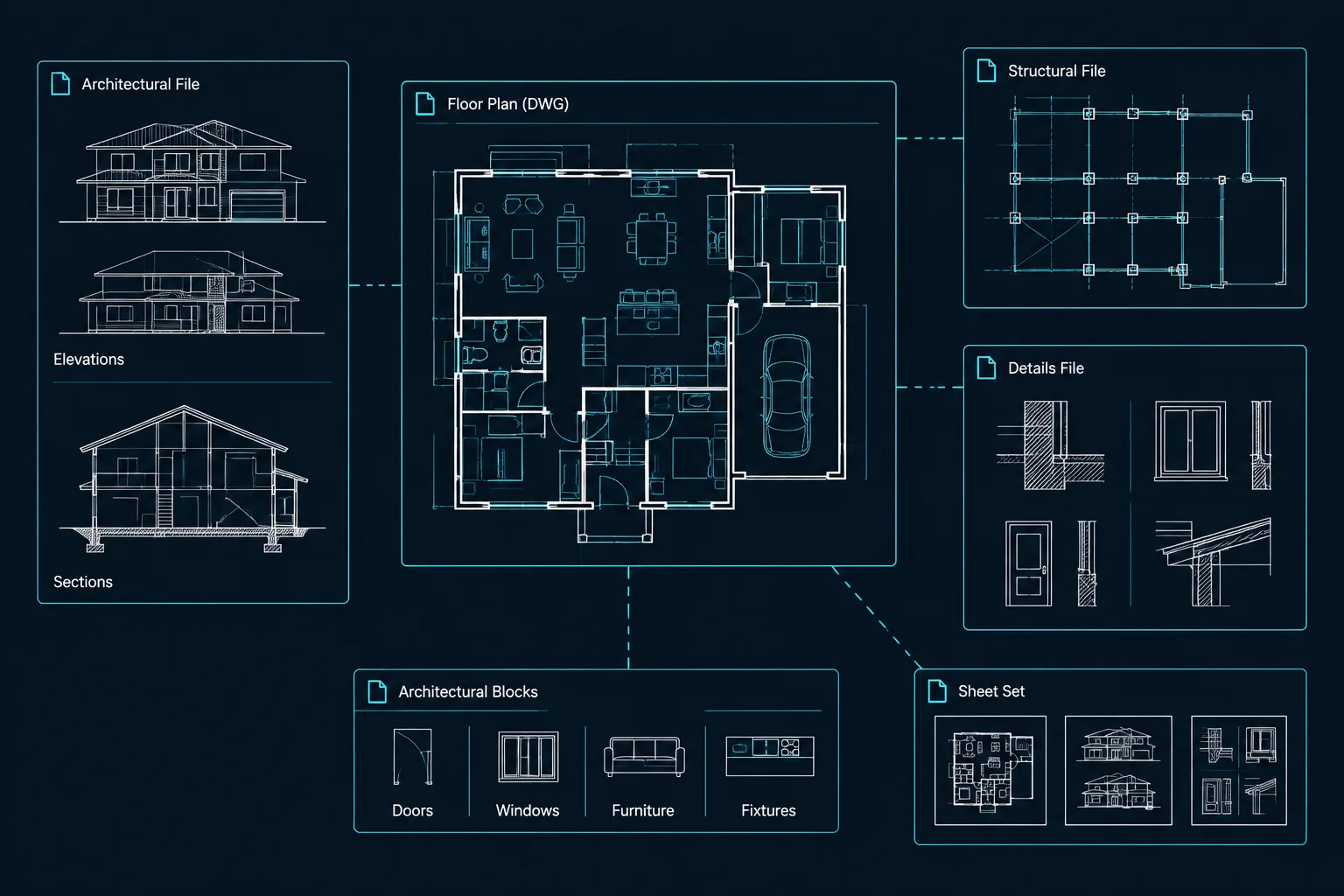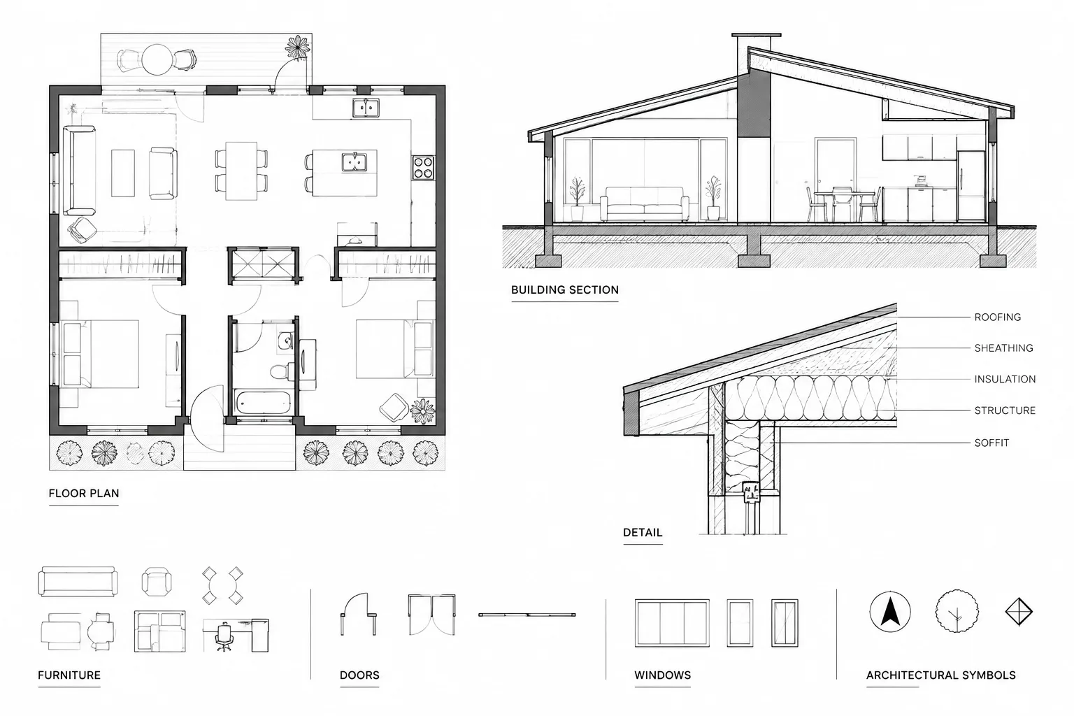
Architectural CAD hatch patterns are most effective when they clarify materials, cut conditions, finishes, and drawing hierarchy without overwhelming the underlying geometry. Their success depends on more than pattern selection: boundary quality, plotted appearance, alignment, layer control, and future editability all affect the finished sheet.
The following workflow approaches hatching as coordinated drawing information. Use it to evaluate whether a pattern communicates clearly, remains manageable during revisions, and supports consistent output across plans, elevations, sections, and details.
Hatch patterns help readers distinguish materials, identify cut elements, understand finish extents, and interpret surfaces that would otherwise look alike. They can also make a DWG difficult to edit or a plotted sheet difficult to read when pattern scale, boundaries, origins, and display priorities are not managed carefully.
A reliable hatching workflow is not simply a matter of choosing a pattern that resembles a material. The pattern must support the purpose of the view, remain legible at the intended drawing scale, and behave predictably when surrounding geometry changes. This guide explains how to use architectural CAD hatch patterns as coordinated drawing information rather than as decoration.
Decide What the Hatch Needs to Communicate
Before applying a pattern, identify its job in the drawing. The same physical material may need different graphic treatment in a floor plan, elevation, wall section, and enlarged detail.
- Cut material: A hatch can identify construction intersected by the view’s cut plane.
- Surface material: A pattern may indicate masonry coursing, panels, paving, roofing, or another visible finish.
- Finish extent: Hatching can show where tile, resilient flooring, wall protection, or another finish begins and ends.
- Diagrammatic area: A simple solid or screened hatch can distinguish zones, scope boundaries, departments, or work phases.
- Depth and hierarchy: Subtle poche can separate cut construction from elements seen beyond.
If a hatch does not convey information needed to read or coordinate the drawing, consider omitting it. Unnecessary patterns increase visual noise and can hide dimensions, symbols, and small construction lines.
Choose Patterns for Readability, Not Realism
Architectural drawings are abstractions. A highly literal texture is not always the clearest representation of a material. Dense or irregular patterns may look convincing on screen but merge into a dark mass when plotted or reduced.
Use simple, recognizable patterns where possible. Distinguish materials through a controlled combination of pattern geometry, density, lineweight, and screening rather than relying on intricate graphics. A material legend can clarify pattern meanings when several similar fills occur on the same sheet.
| Drawing condition | Useful graphic approach | Common risk |
|---|---|---|
| Cut construction | Strong poche or a clear material hatch | Competing with outlines and dimensions |
| Surface finish | Light line pattern with a controlled origin | Appearing too dense at plotted scale |
| Large diagrammatic zone | Simple screened or solid fill | Obscuring text and reference symbols |
| Small detail component | Simplified hatch appropriate to the view | Pattern becoming too fine to reproduce |
| Existing or background information | Subdued graphic treatment | Reading as new or primary work |
Test Pattern Scale at the Intended Output
Hatch scale should be judged on the sheet, not only in model space. A pattern that looks comfortably spaced while zoomed in can become illegible in a plotted viewport. Conversely, a pattern selected for a small-scale plan may look oversized and crude in an enlarged detail.
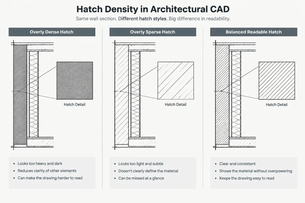
Start with the intended sheet view and adjust the pattern until its spacing supports the material indication without dominating the drawing. Then test a PDF or physical print under normal viewing conditions. Check both the full sheet and any reduced reproduction that may be used for review.
Do not assume that one hatch scale will work in every view. When the same geometry appears in views at different scales, separate hatch objects or view-specific graphic treatments may be necessary. Document the office approach so that similar details do not receive visibly inconsistent pattern densities.
Build Clean and Deliberate Boundaries
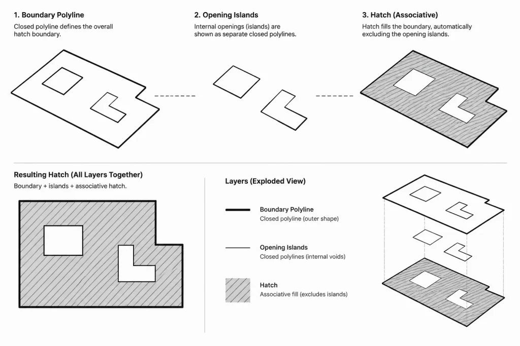
Most hatch failures begin with boundary geometry. Tiny gaps, overlapping segments, duplicate lines, and objects at unintended elevations can prevent a region from being recognized correctly. Complex drawings may also contain numerous internal islands that make boundary detection slow or unpredictable.
For important or frequently edited areas, create deliberate closed boundaries instead of relying on a click inside a visually enclosed space. A closed polyline can make the intended hatch extent easier to inspect, edit, and reuse. Place helper boundaries on a controlled layer if they should not plot.
Boundary checklist
- Confirm that the perimeter is closed and does not cross itself.
- Remove duplicate or overlapping segments that serve no drafting purpose.
- Check whether internal openings should remain unhatched.
- Verify that all boundary objects lie in the intended drawing plane.
- Simplify unnecessarily detailed boundaries before creating large hatches.
- Keep the boundary when it will help future editing or quality control.
A tolerance setting may help diagnose a minor gap, but it should not become a substitute for repairing unreliable geometry. A hatch that succeeds only because a large gap tolerance is permitted may conceal a drafting error elsewhere in the file.
Use Associative Hatches Selectively
An associative hatch updates when its recognized boundary changes. This is useful for rooms, paving fields, wall components, and finish areas that are likely to be revised. The relationship can reduce repetitive editing and help keep the pattern aligned with the design.
Association is less useful when boundaries are unstable, excessively complex, or assembled from referenced geometry that changes outside the current file. In those cases, updates may produce unexpected islands or extents. Choose association based on how the drawing will be maintained, not as an automatic default.
After moving walls, openings, fixtures, or finish limits, inspect the hatch directly. Do not assume that association alone guarantees a correct result. Confirm that openings remain clear and that the revised pattern has not extended into adjacent construction.
Control Pattern Origin and Alignment
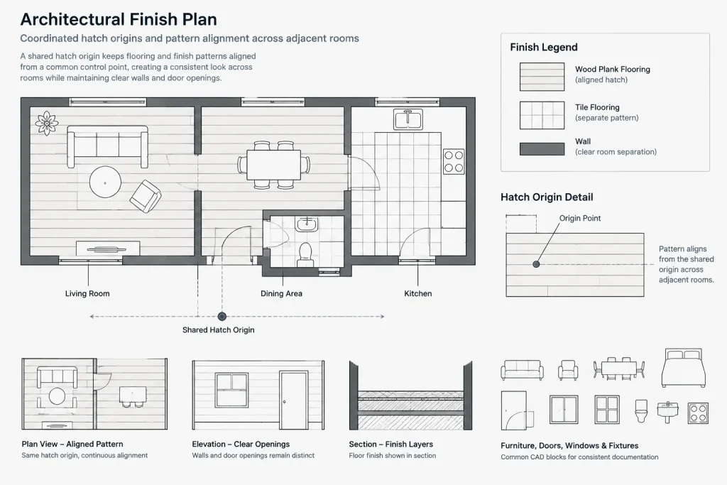
Pattern origin matters whenever modules, joints, courses, or repeated units need to align with architecture. A random origin can make tile, panel, ceiling, or paving layouts appear arbitrary even if the spacing is otherwise correct.
Select a meaningful reference point such as a room corner, control line, building grid intersection, or established finish datum. Use the same reference logic for related areas. When a pattern continues across separate hatch objects, coordinate their origins so that the graphic does not jump at an artificial boundary.
Do not let a hatch pattern imply construction alignment that has not been designed. If joints or modules affect dimensions, cuts, fixtures, or fabrication, they should be treated as coordinated layout information rather than a generic material symbol.
Organize Hatches with Layers and Properties
Hatches should be separable from outlines, annotations, and reference geometry. Dedicated layers make it easier to control visibility, plotting, and viewport-specific presentation. Depending on project complexity, layers may distinguish cut poche, surface materials, finish patterns, diagram fills, and nonplotting hatch boundaries.
Keep color, transparency, linetype, and lineweight controlled through the project’s established property system whenever practical. Unexplained object overrides make global adjustments difficult and can produce inconsistent plots.
Layer names should describe the hatch’s drawing role rather than only its visual appearance. A name such as “light hatch” becomes ambiguous when plot settings change, while a role-based name remains understandable to other users.
Manage Draw Order and Annotation Conflicts
Hatches generally belong behind object outlines, symbols, dimensions, and notes. Solid fills are especially likely to conceal information if their draw order is incorrect. After creating or editing a hatch, verify that doors, fixtures, detail lines, and annotation remain visible.
Background masks can improve isolated text conflicts, but widespread masking may indicate that the hatch is too dense or too prominent. First consider reducing visual weight, simplifying the pattern, or limiting its extent. The goal is to preserve a clear reading hierarchy rather than patch every conflict individually.
Troubleshoot Common Hatch Problems
The hatch will not generate
Inspect the boundary for gaps, overlaps, self-intersections, and elevation differences. Isolate the relevant geometry and create a clean closed perimeter if automatic detection remains unreliable.
The pattern appears solid
The pattern may be too dense for the current view or output scale. Review pattern scale and confirm the result in a plotted test. Also check whether a solid hatch was applied unintentionally.
The hatch disappears in a viewport or PDF
Check layer visibility, viewport overrides, object properties, draw order, and plot settings. Confirm that the hatch is not using a color or screening treatment that becomes effectively invisible against the sheet background.
Editing becomes slow
Large hatches with intricate boundaries or many islands can affect file performance. Divide extensive fields into logical regions, simplify the perimeter, and avoid using highly complex patterns where a simpler graphic would communicate the same information.
Patterns do not align across adjacent areas
Compare hatch origin, angle, scale, and boundary conditions. Establish a shared architectural reference rather than adjusting each pattern by eye.
A Practical Quality-Control Sequence
- Confirm that each hatch has a clear communication purpose.
- Check the pattern against the drawing legend and office conventions.
- Review scale, density, and orientation in the intended sheet viewport.
- Inspect boundaries, islands, penetrations, and transitions.
- Verify alignment where a module or course is being represented.
- Check layer assignment, properties, and draw order.
- Plot or export a test and examine dense areas at normal viewing size.
- Review the hatch again after relevant geometry is revised.
Well-managed architectural CAD hatch patterns strengthen material communication and drawing hierarchy without calling attention to themselves. By using deliberate boundaries, meaningful origins, appropriate pattern density, and sheet-based quality control, a drafting team can produce files that remain clear, editable, and dependable throughout coordination.
Coordinate Hatch Decisions Across the Drawing Set
A hatch should be interpreted consistently wherever the same graphic convention appears. Before issuing a drawing set, compare related plans, elevations, sections, details, and legends. Confirm that similar materials are represented intentionally and that differences in appearance reflect the purpose and scale of each view rather than accidental property changes.
Consistency does not require every occurrence of a material to use an identical pattern treatment. A broad surface shown in elevation may need a lighter presentation than the same material shown in section. What matters is that the visual choice supports the view and remains understandable when read with the drawing legend.
Prepare Hatches for File Handoffs
Hatch behavior can become difficult to diagnose when another user receives a DWG without understanding its layer structure, boundaries, or reference points. Before a handoff, remove abandoned test hatches, retain useful boundary objects, and verify that custom patterns required for interpretation are available through the project’s established file-management process.
Review whether important fields depend on referenced or unusually complex boundary geometry. If the relationship is fragile, document the intended extent or replace it with a more deliberate boundary. A clean handoff allows the next drafter to understand why the hatch exists and how it should respond to revisions.
Use Sheet Review as the Final Standard
On-screen appearance is only an intermediate check. The final judgment should be based on the issued sheet format because viewport scale, plotting properties, screening, and surrounding annotation can alter how a pattern reads.
- Readability: The represented material or area can be identified without obscuring nearby information.
- Hierarchy: Cut elements, surface patterns, background information, and annotation remain visually distinct.
- Continuity: Related fields align where continuity is intentional.
- Editability: Boundaries and layer assignments can be understood by another CAD user.
- Coordination: Hatches agree with openings, fixtures, joints, finish limits, and other visible geometry.
Treat this review as part of drawing coordination rather than cosmetic cleanup. A clear hatch can reveal an extent or alignment issue, while a poorly controlled hatch can conceal one.
Frequently Asked Questions
Should every material have a unique hatch pattern?
No. The graphic system should distinguish information that readers need to understand in a particular view. Similar or simplified treatments may be appropriate when a legend, note, outline, or other drawing convention already communicates the difference.
Why does a hatch look correct in model space but too heavy on the sheet?
The viewing conditions are different. Viewport presentation, plotted linework, screening, and reduction can make pattern lines merge visually. Evaluate density in the intended sheet context and confirm it through an output test.
Is a closed polyline always required for a hatch boundary?
Not necessarily, but a deliberate closed boundary is often easier to inspect and revise than a perimeter detected from many unrelated objects. It can be especially helpful in crowded drawings or areas expected to change.
When should associative hatching be avoided?
Consider avoiding or limiting association when the recognized boundary is unstable, overly complex, or dependent on geometry that changes outside the current drawing. The appropriate choice depends on how the file will be revised and maintained.
How should custom hatch patterns be handled during coordination?
Use the project’s established file-management method and verify that collaborators can display and plot the intended pattern. If availability is uncertain, choose a dependable graphic alternative that preserves the required meaning.
Can hatch patterns represent actual construction layout?
They can, but only when the origin, orientation, joints, and transitions have been deliberately coordinated. A generic material hatch should not be assumed to define installation, fabrication, or setting-out information.