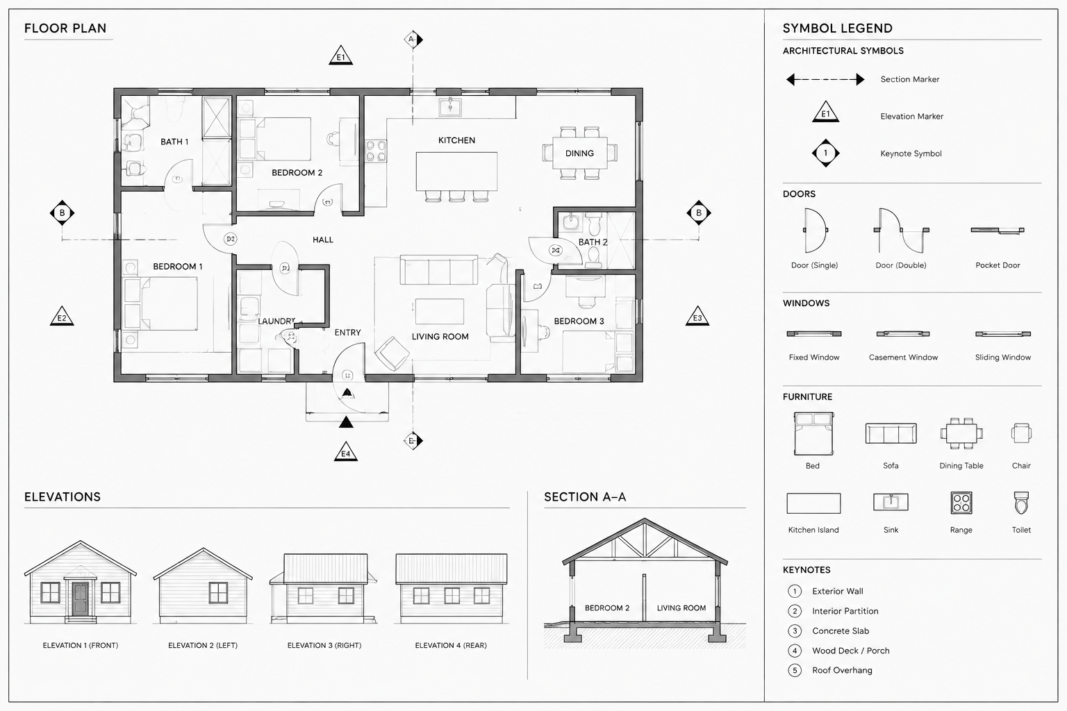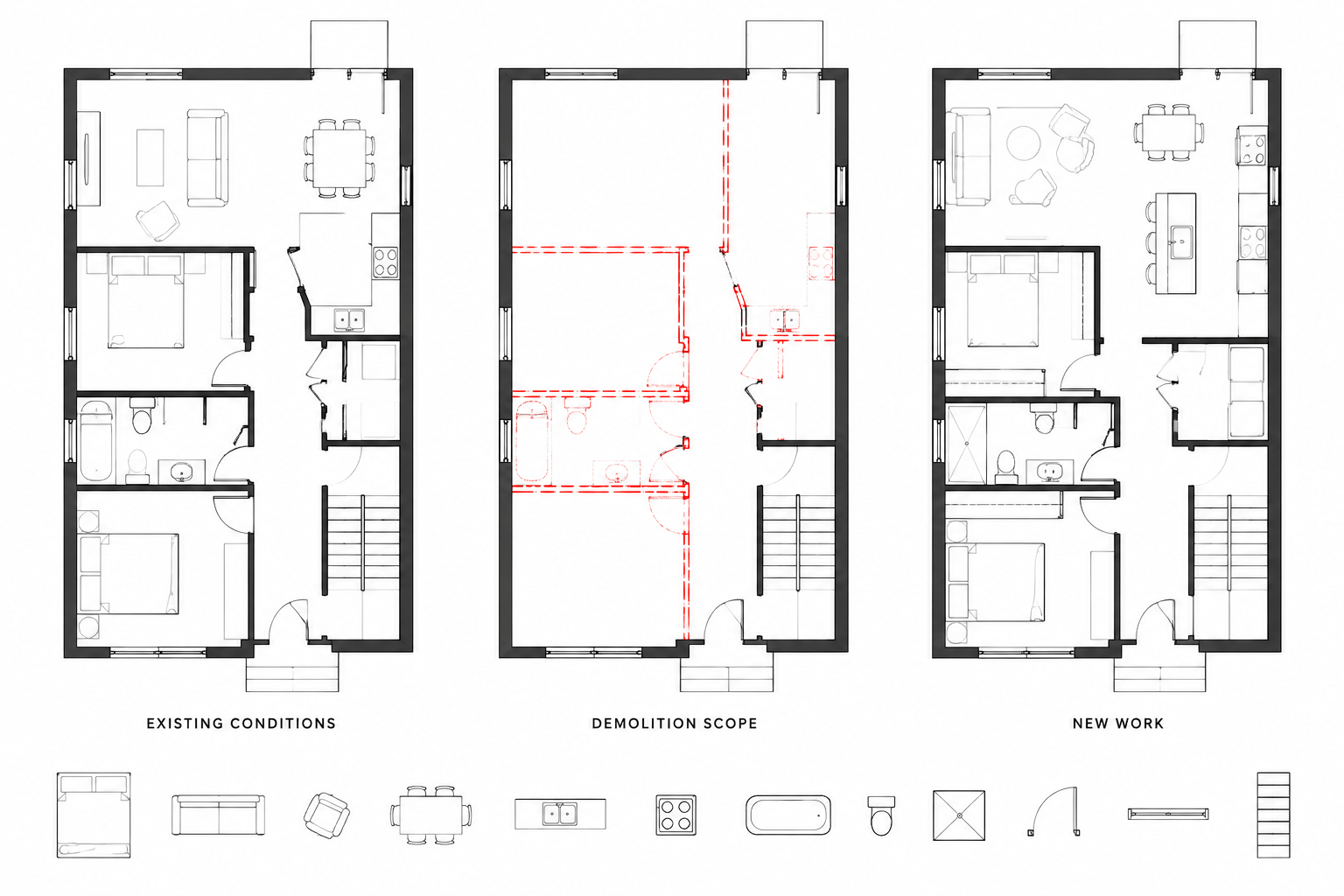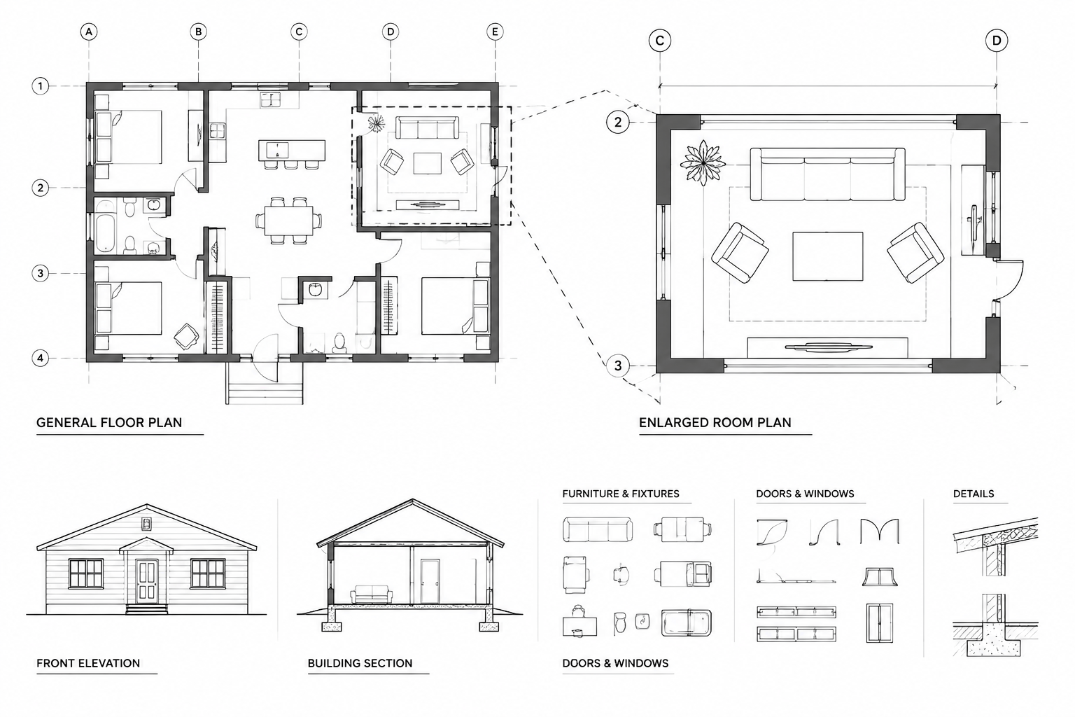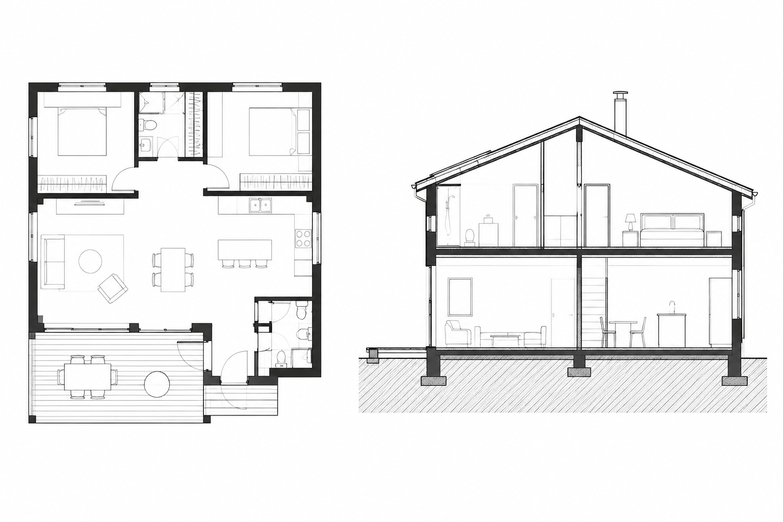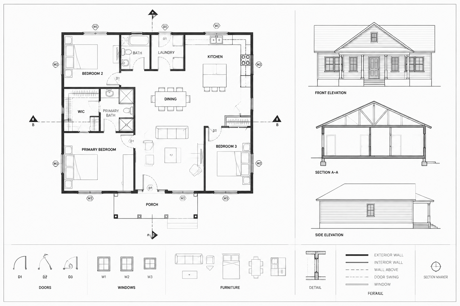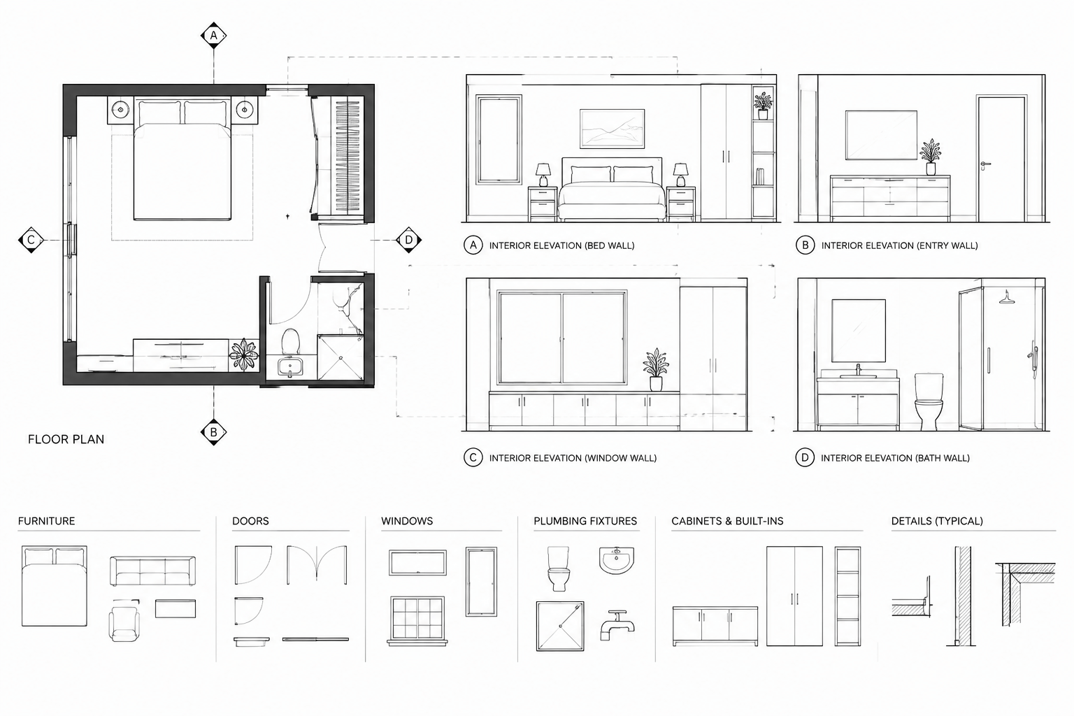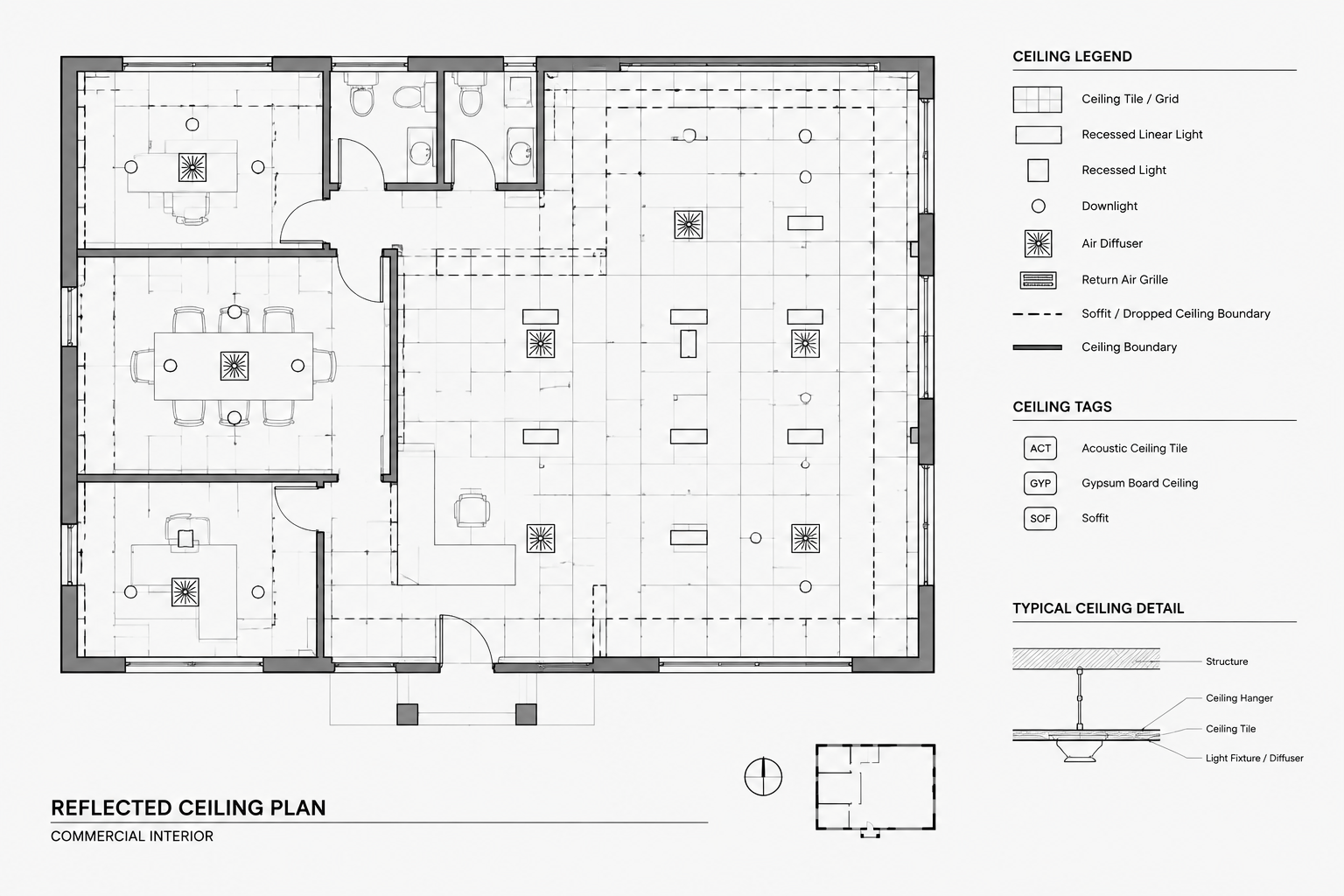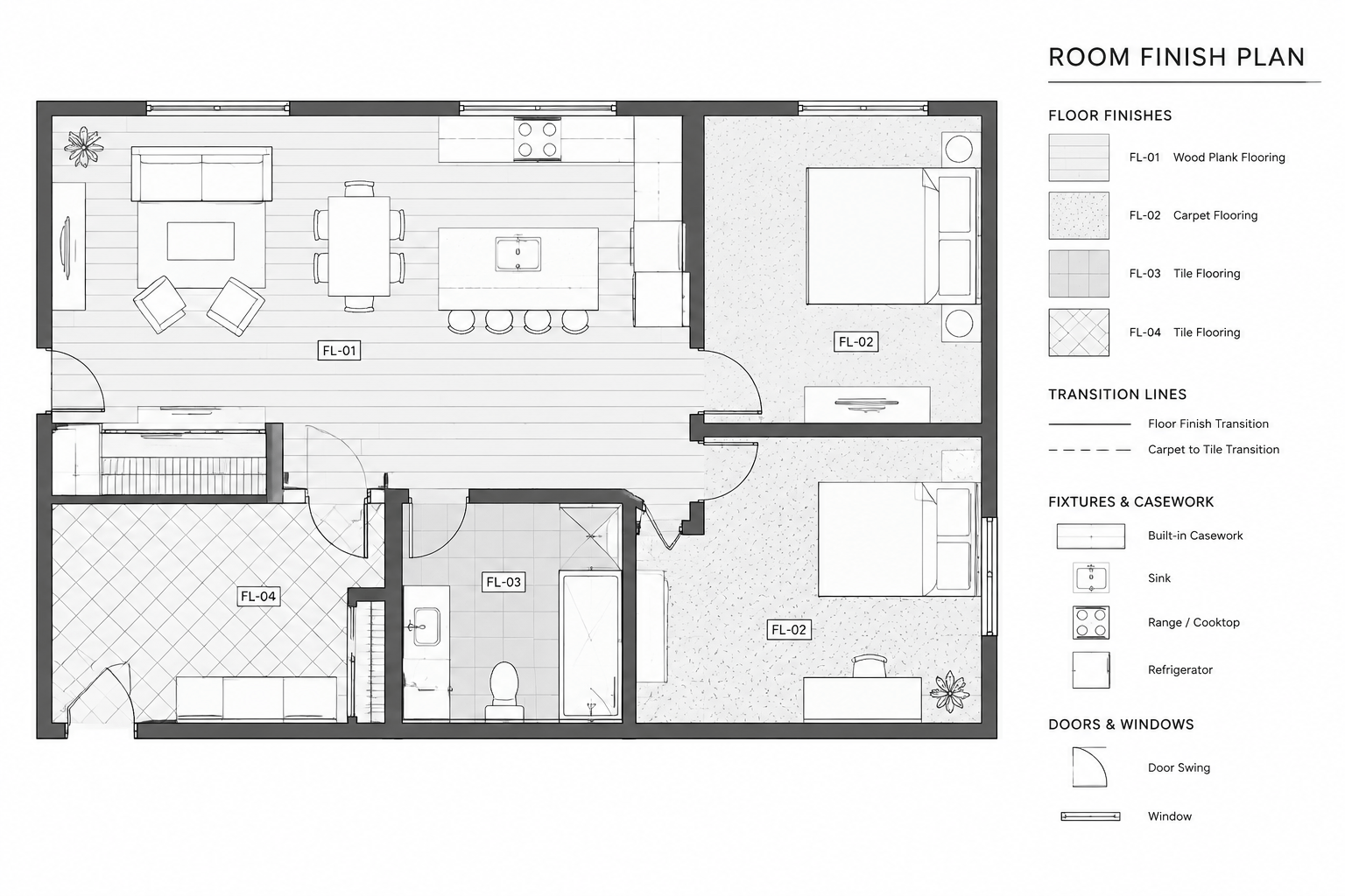
A room finish plan communicates where architectural finishes occur and how they relate to rooms, doors, walls, casework, and other building elements. Depending on the project, it may document flooring alone or coordinate floor, base, wall, and ceiling finishes with a room finish schedule.
The drawing should do more than fill rooms with hatch patterns. A useful finish plan identifies changes within rooms, explains transitions, and gives the schedule enough location information to be interpreted correctly. The drafting process therefore depends on consistent room data, controlled graphics, and careful coordination with the architectural plans.
What a room finish plan should communicate
The exact scope varies by project. Some drawing sets use a dedicated finish floor plan, while others show finish information on an enlarged plan or interior design sheet. A room finish plan may communicate:
- Floor finish extents and changes in material
- Finish transitions at doors or open connections
- Base finish types and exceptions
- Wall finish locations, including accent surfaces
- Room finish tags linked to a schedule
- Finish direction, alignment, or pattern origin when relevant
- Special notes for borders, insets, thresholds, or feature areas
Not every finish needs to be drawn with the same method. A uniform floor material may be identified by a room tag, while a floor with several materials usually requires visible boundaries and separate labels. Wall finishes may be easier to describe with keyed notes, directional symbols, or wall-specific tags than with dense plan hatching.
Begin with a coordinated architectural background
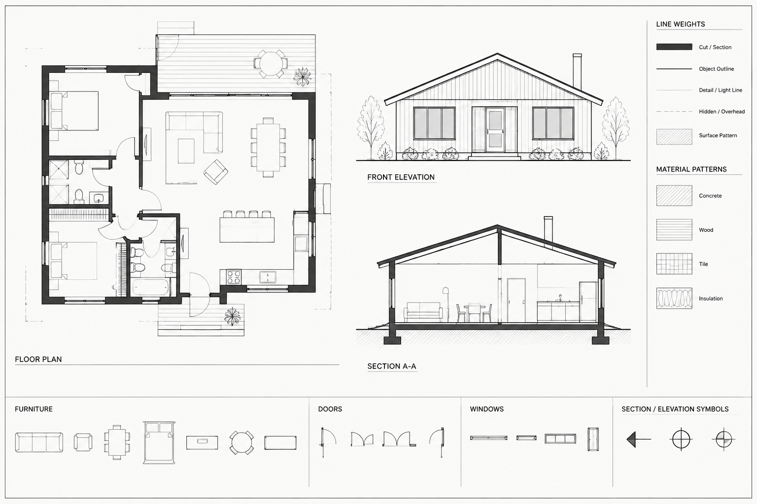
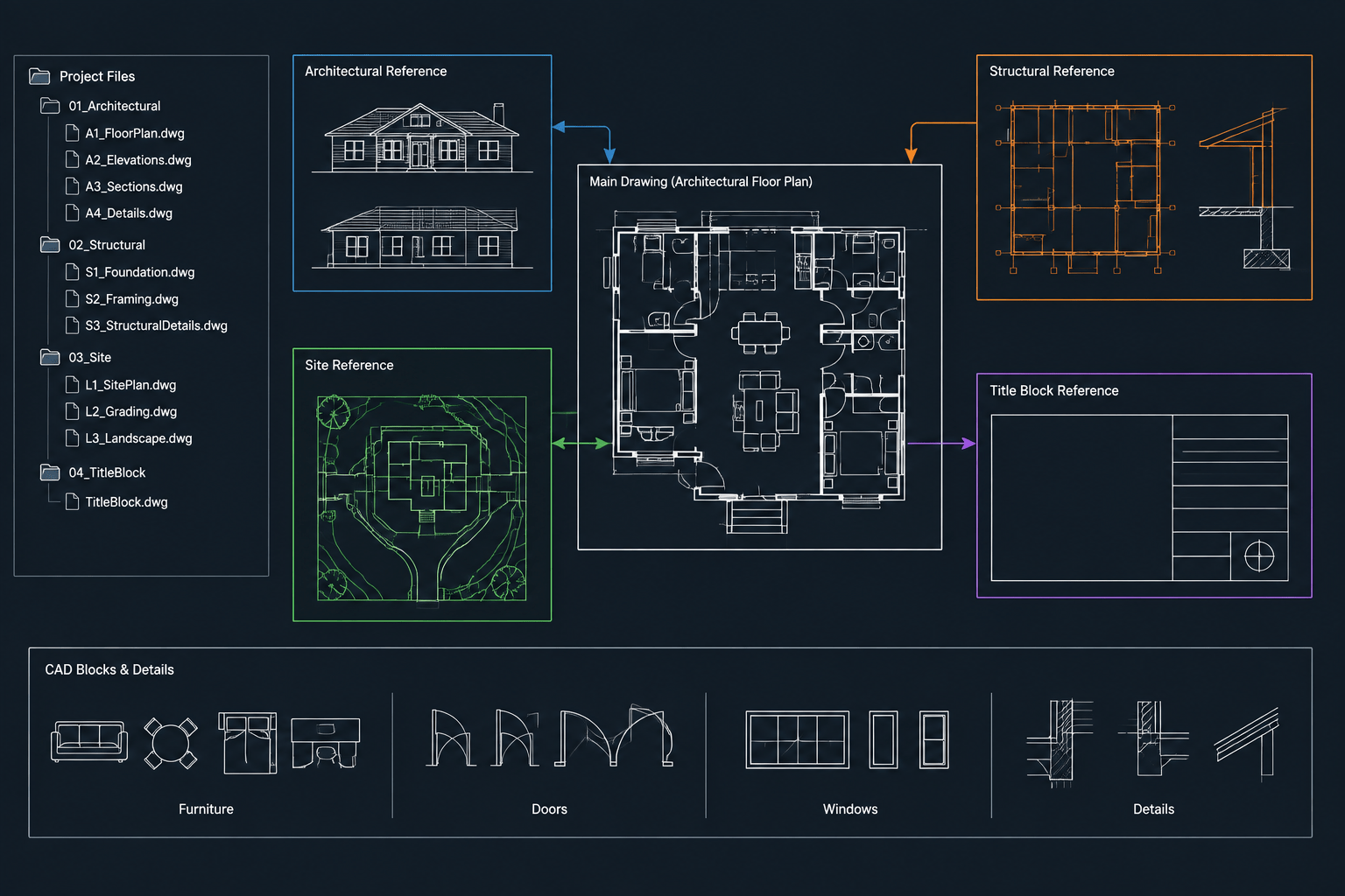
Use the current architectural floor plan as the background for the finish drawing. The plan should already contain coordinated walls, openings, room boundaries, fixed casework, plumbing fixtures, and major built-in elements. If the project uses external references, keep the finish annotation in its own drawing rather than editing the referenced architectural plan.
Before adding finish information, review the background for conditions that affect material extents. These include wall recesses, columns, alcoves, islands, floor-mounted equipment, millwork, and changes between enclosed rooms and open circulation areas. A finish boundary based only on the room name may miss these local conditions.
Reduce the visual prominence of background elements so finish information remains easy to read. Walls and major architectural edges should still provide orientation, but furniture and secondary equipment should not compete with finish tags and transition lines.
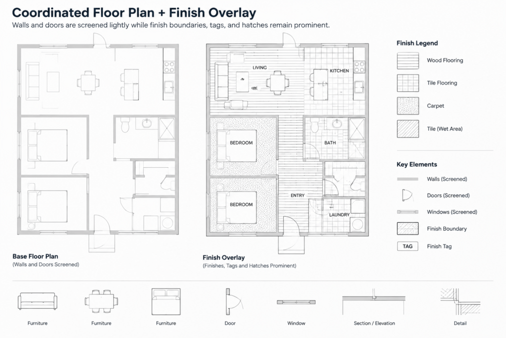
Establish a finish coding system before drafting
Agree on the relationship between plan labels, material specifications, and the finish schedule before placing many tags. A short finish code is useful only when it remains consistent across the drawing set.
| Information type | Common drawing method | Coordination concern |
|---|---|---|
| Room-wide floor finish | Room tag or finish symbol | Confirm the finish applies to the complete room |
| Multiple floor finishes | Boundaries, hatches, and individual tags | Locate every transition clearly |
| Base finish | Schedule entry or local keynote | Identify walls where the typical base does not apply |
| Wall finish | Schedule entry, wall tag, or directional note | Distinguish individual walls and partial-height areas |
| Ceiling finish | Finish schedule or reflected ceiling plan reference | Avoid conflicting information between plans |
Codes should be unique and readable without relying on hatch appearance. Similar materials may plot with nearly identical tones, and users may view the drawing without color. The written code remains the primary identifier; hatching is a supporting graphic.
Organize finish information on dedicated CAD layers
Separate finish content by function so it can be edited and displayed without disturbing the background plan. A project may use distinct layers for finish boundaries, hatches, tags, transition symbols, notes, and overhead references. Follow the office or project layer system rather than creating unrelated naming conventions inside one sheet.
Keeping boundaries separate from hatches is especially helpful. The boundary line may need to remain visible while a hatch is screened, hidden, or replaced. Tags should also remain independent so they can be repositioned without rebuilding the graphic pattern.
Draw floor finish boundaries intentionally
Use closed, clean boundaries for areas that receive different floor finishes. Trace the actual exposed floor area rather than simply outlining the room walls. Consider casework, raised platforms, floor openings, fixed bases, and other elements that interrupt the finish.
Where adjacent materials meet, place the transition line at a location that can be understood and constructed. Door openings require particular attention. The plan should make clear whether the change aligns with a door, frame, wall face, or another defined architectural edge. Do not assume the contractor will infer an intended transition from two nearby hatch patterns.
For open-plan spaces, use architectural features to establish logical finish zones. A change may align with a partition, ceiling feature, counter edge, column line, or other coordinated element. If no physical feature defines the change, provide dimensions or another explicit locating method appropriate to the project documentation.
Use hatches as graphic aids, not as the specification
Hatches can distinguish finish zones and indicate general material character, but they should not be treated as a complete description of the product or installation. A tile-like grid, for example, does not automatically establish exact module size, joint layout, or installation requirements.
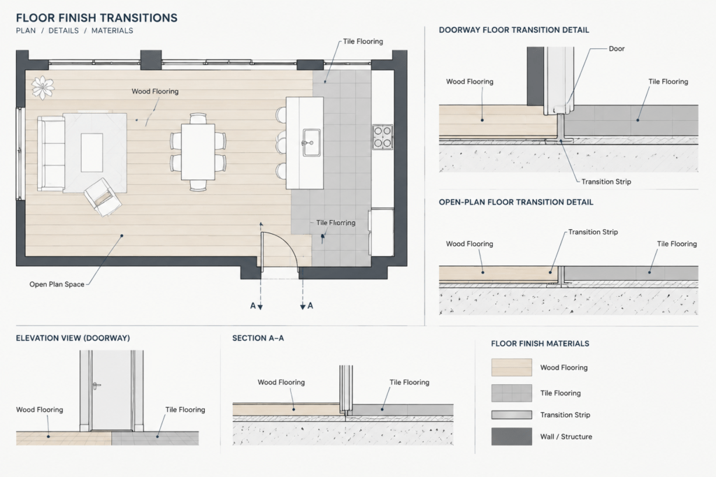
Choose patterns that remain legible at the plotted sheet scale. Overly dense patterns can obscure walls, tags, and door swings, while very large patterns can make small spaces difficult to interpret. Review the plotted result rather than judging only from a close model-space view.
When pattern direction matters, include a direction symbol, start-point note, or clearly coordinated layout graphic. Avoid implying a precise installation layout when the drawing is intended only to identify material extent.
Place finish tags for fast plan reading
Position each finish tag within or immediately beside the area it identifies. Use leaders when the tag could be associated with more than one zone. In small rooms, place the tag in a clear adjacent area and point to the finish boundary rather than crowding fixtures and dimensions.
A finish tag may identify only the floor material, or it may combine floor, base, wall, and ceiling references. Whichever method is selected, use it consistently. Avoid mixing full room-finish tags and floor-only tags without a clear graphic distinction.
Repeat a tag when a finish area is interrupted or when one label would require the reader to make an uncertain connection. Repetition is usually preferable to ambiguity, provided all repeated labels remain coordinated.
Document wall finishes and exceptions carefully
Room schedules are efficient for typical wall finishes, but they may not explain accent walls, wet-area finishes, wall protection, backsplashes, or partial-height applications. Show these exceptions with a plan symbol, keyed note, interior elevation reference, or other project-specific method.
Directional wall tags should point to a specific wall face. At corners, confirm that the symbol cannot be read as applying to both walls. If a wall finish stops at a casework edge, opening, or change in height, coordinate the limit with an interior elevation or detail where needed.
Do not duplicate detailed elevation information unnecessarily. The finish plan should locate the condition; the interior elevation can explain its vertical extent and relationship to mounted elements.
Coordinate the plan with the room finish schedule
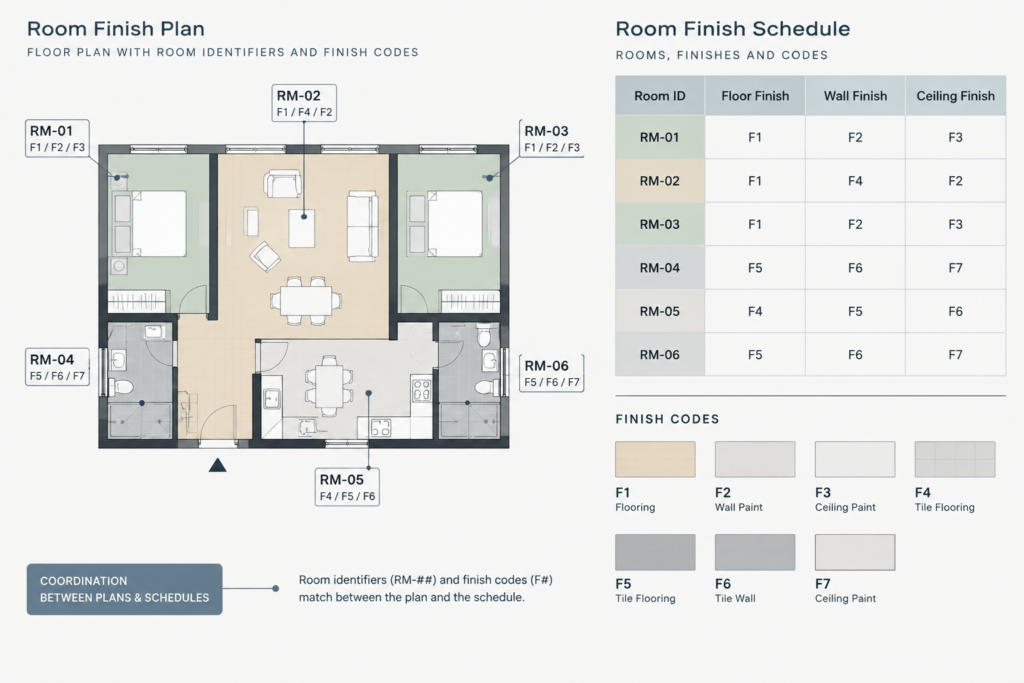
The finish plan and schedule should function as one information system. Room names and room identifiers must match the architectural plan. Finish codes shown graphically must exist in the schedule or finish legend, and scheduled materials must have a clear location.
Check for common coordination failures:
- A room appears on the plan but not in the schedule
- The schedule lists a finish code that is not defined
- A room has multiple floor finishes but only one scheduled entry
- An accent wall is scheduled without identifying which wall receives it
- A finish transition conflicts with a door or casework location
- The ceiling finish differs between the finish schedule and reflected ceiling plan
- Renamed or renumbered rooms retain outdated finish tags
When a room contains several finishes, the schedule can direct the reader to the plan rather than forcing complex location descriptions into a narrow cell. Conversely, the plan can use concise codes while the schedule provides the full material description.
Run a final CAD and drawing review
Before issuing the sheet, inspect both the CAD file and a plotted output. Confirm that hatch boundaries are closed, duplicate patterns are removed, and transition lines are not hidden behind other objects. Check that annotation is readable at the intended sheet scale and that screened background elements remain visible enough for orientation.
Review each room systematically. Start at one area of the plan and compare the room identifier, finish tag, boundaries, notes, and schedule entry before moving to the next space. Then review shared edges between rooms, because transitions are often missed when rooms are checked individually.
Finally, compare the finish plan with interior elevations, reflected ceiling plans, door information, enlarged plans, and relevant details. A well-drafted room finish plan is not an isolated decorative diagram. It is a coordinated architectural drawing that gives each finish a clear identity, extent, and relationship to the building.