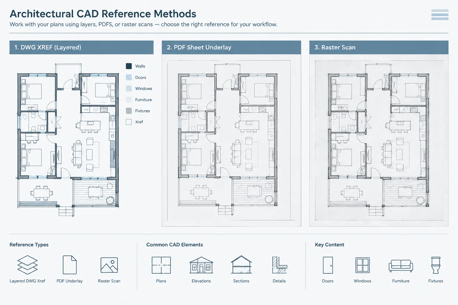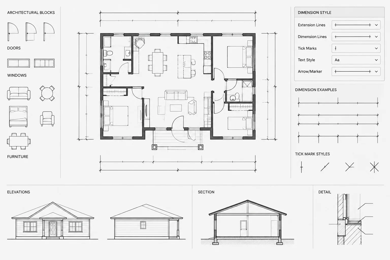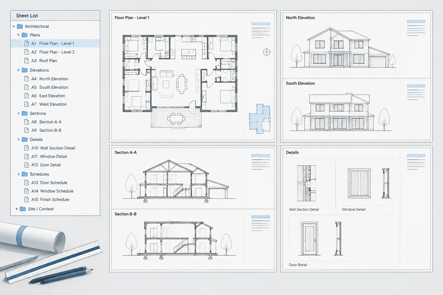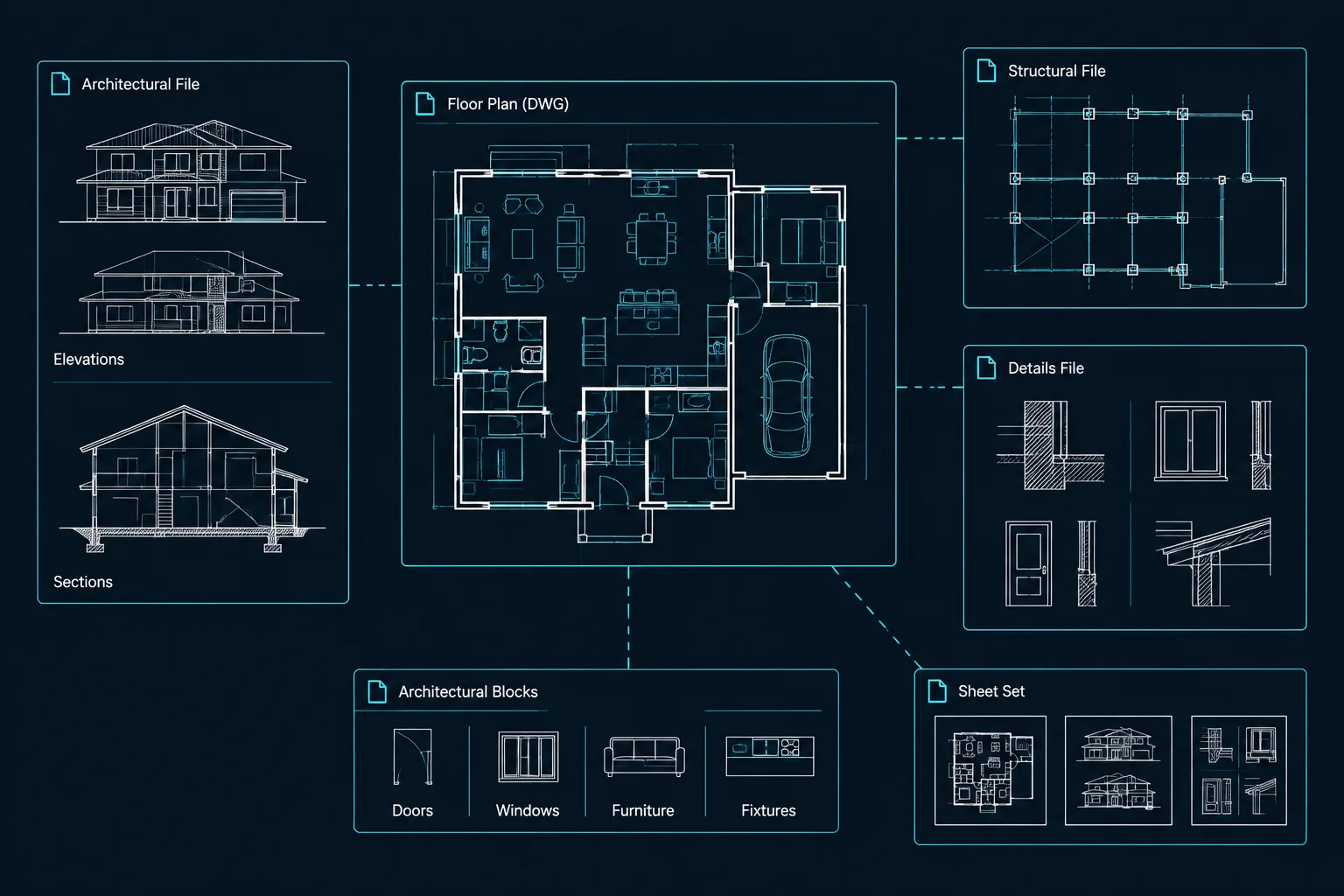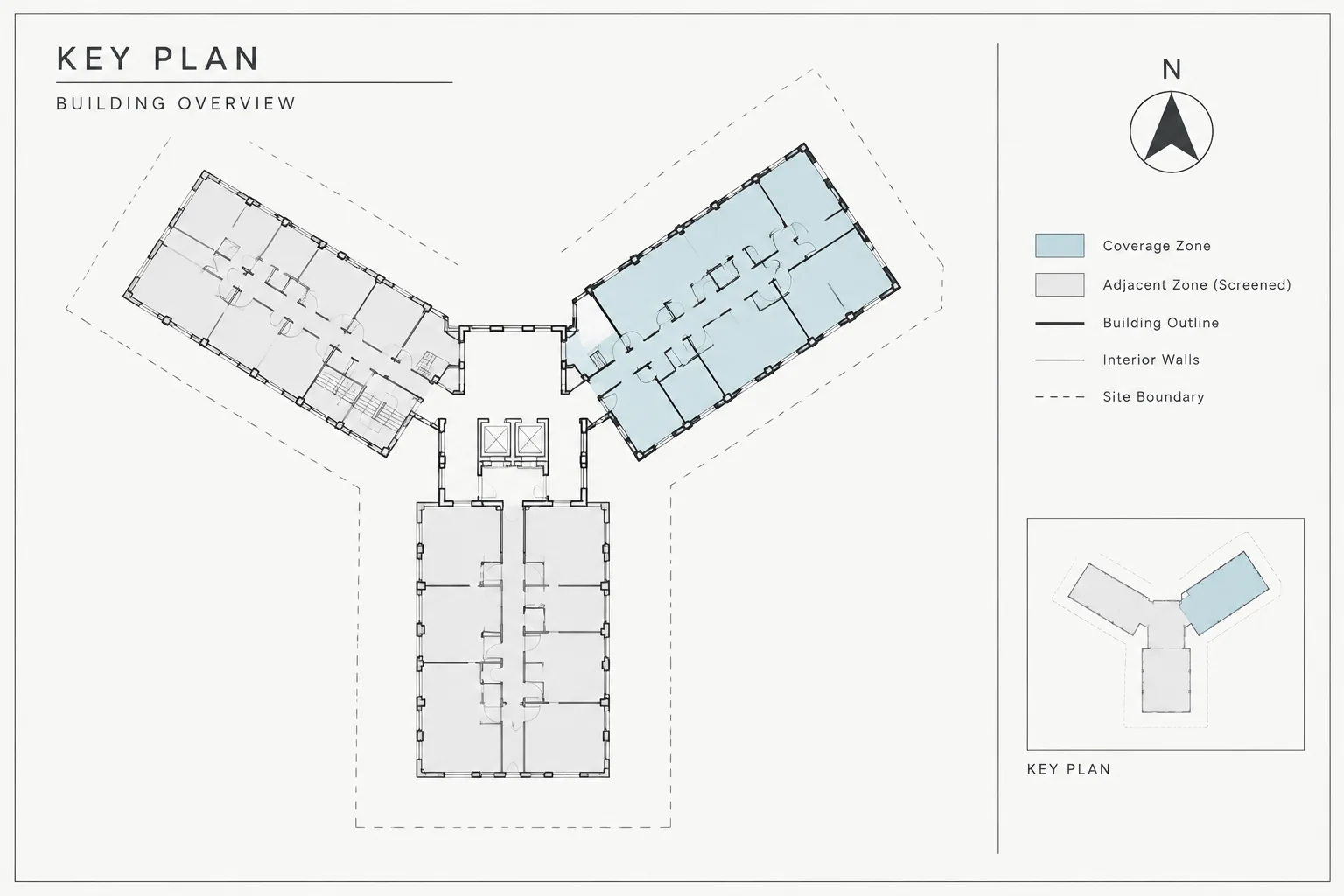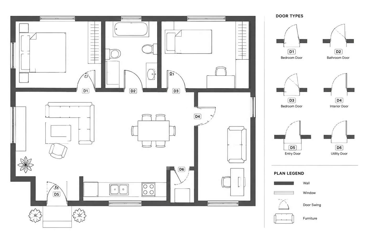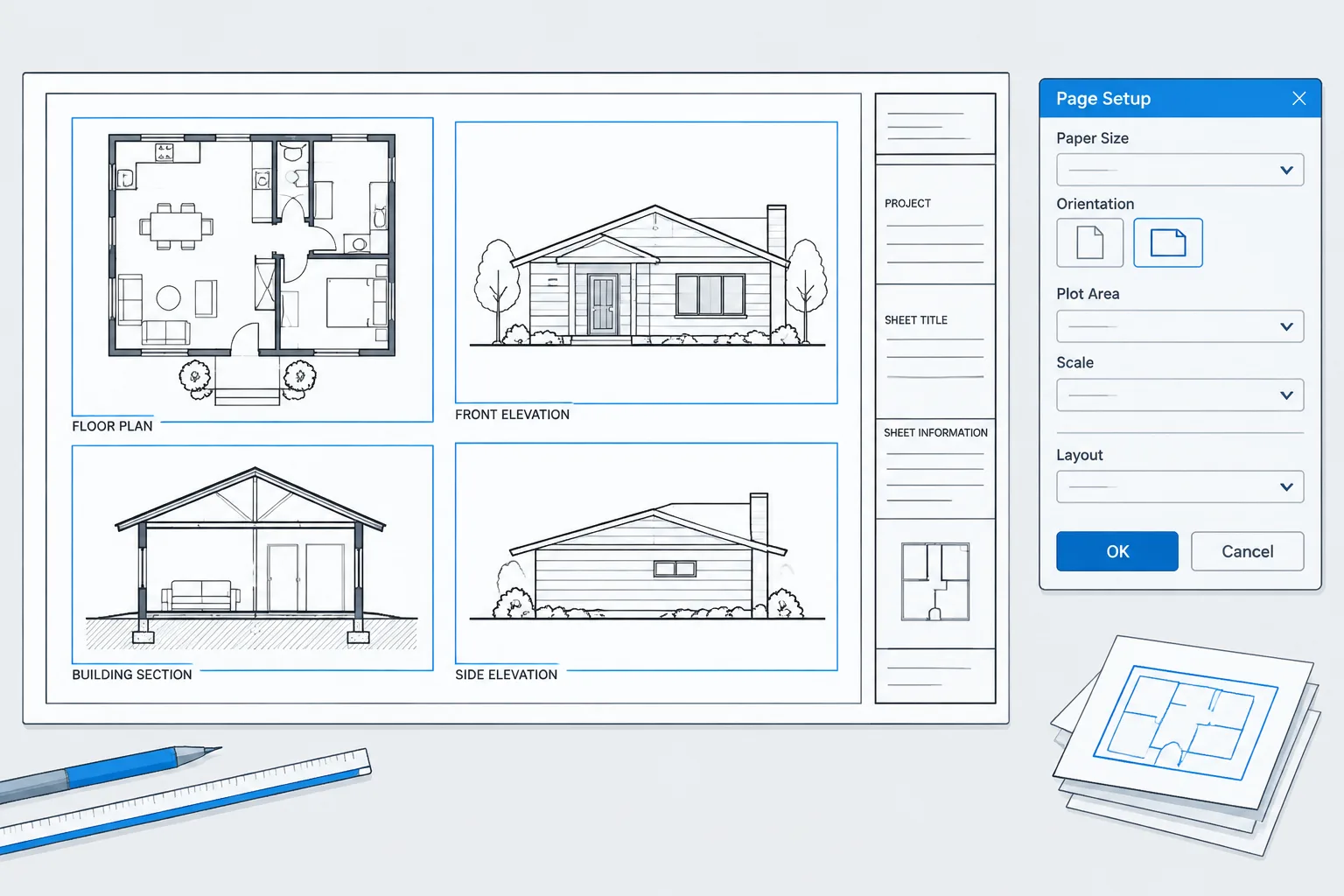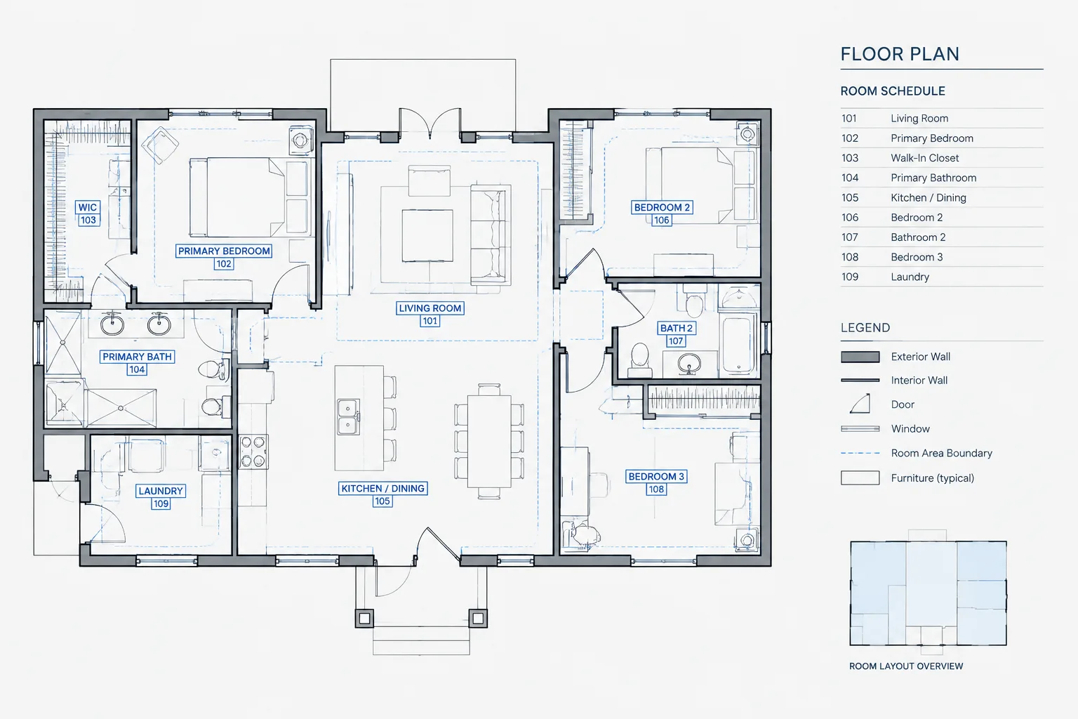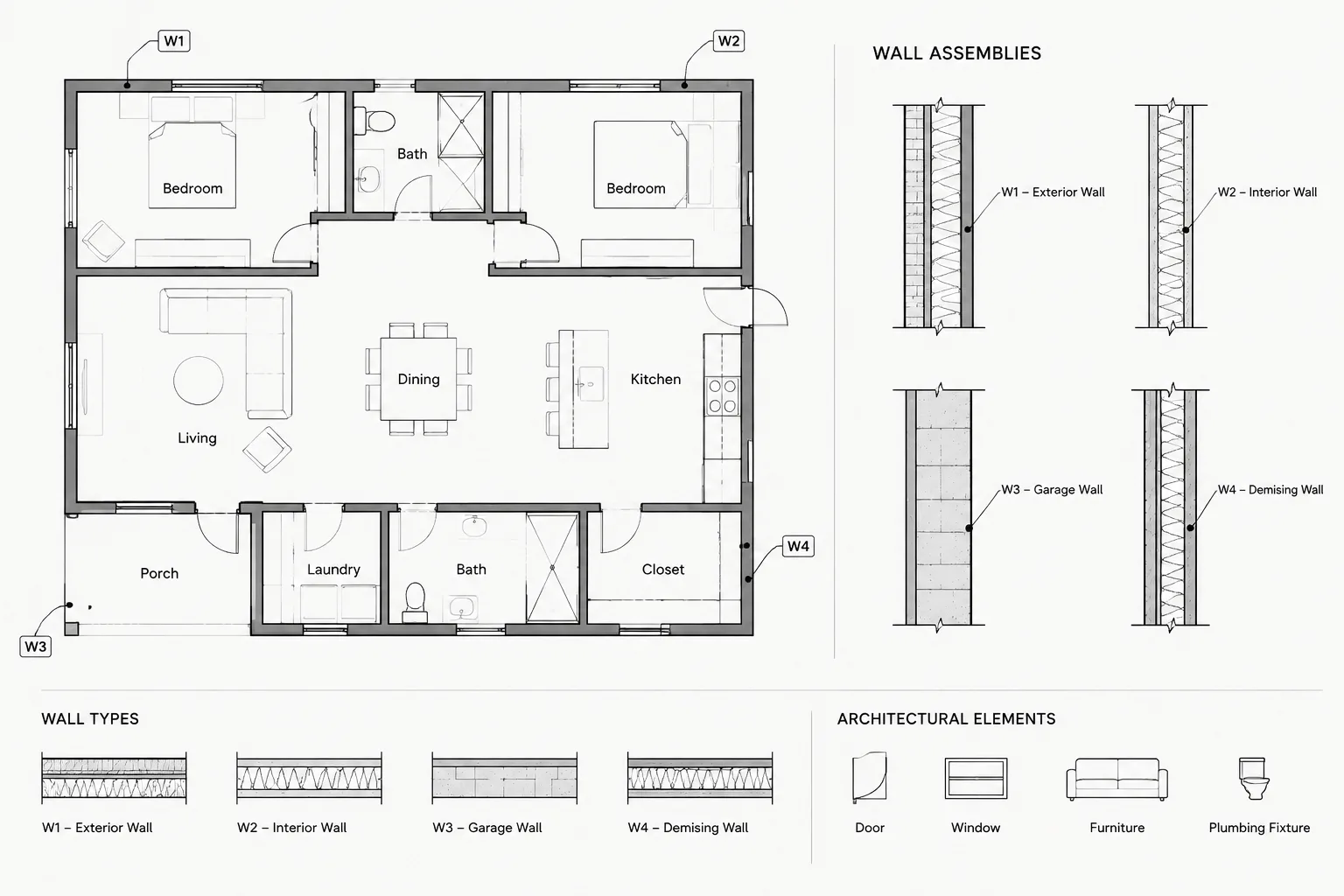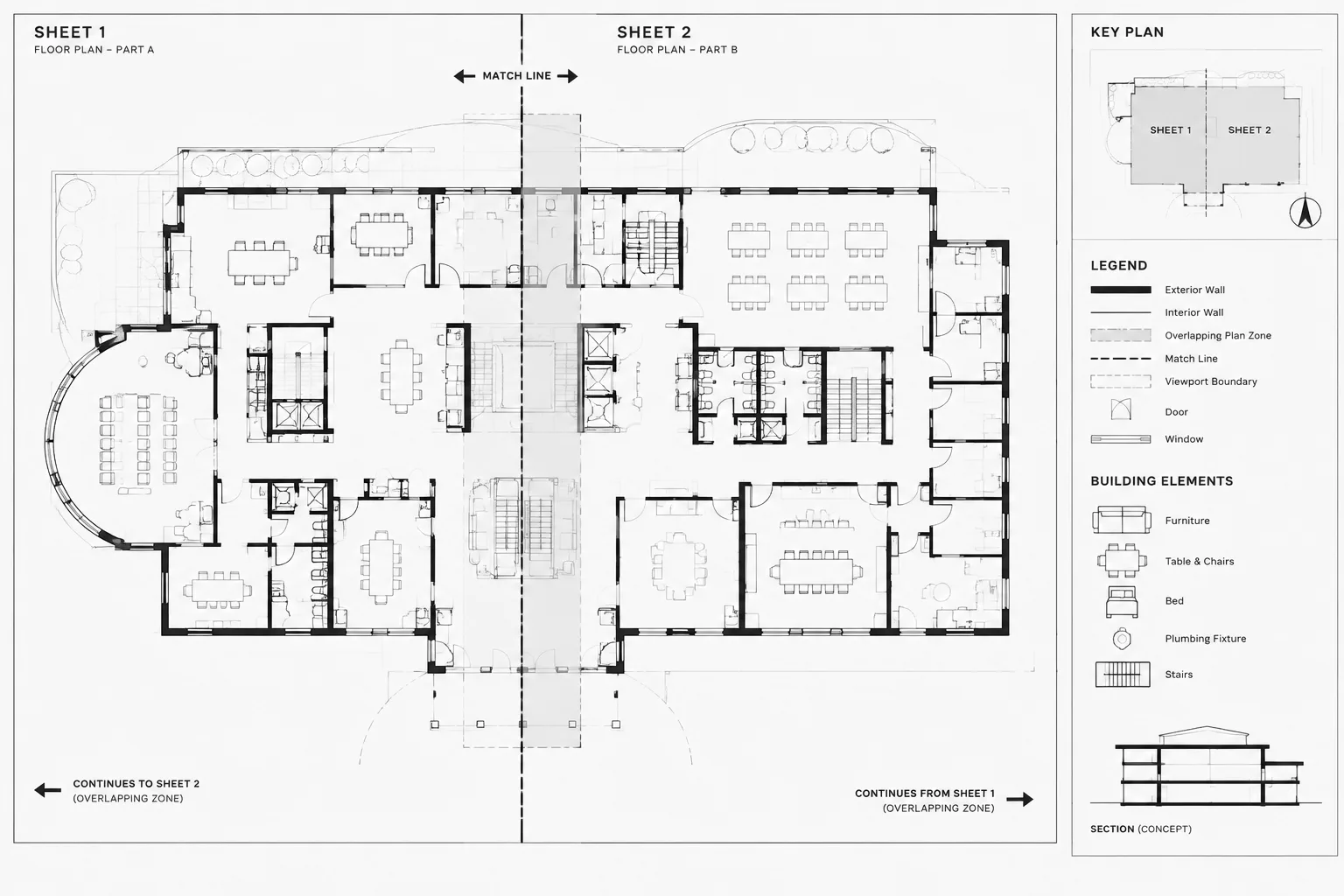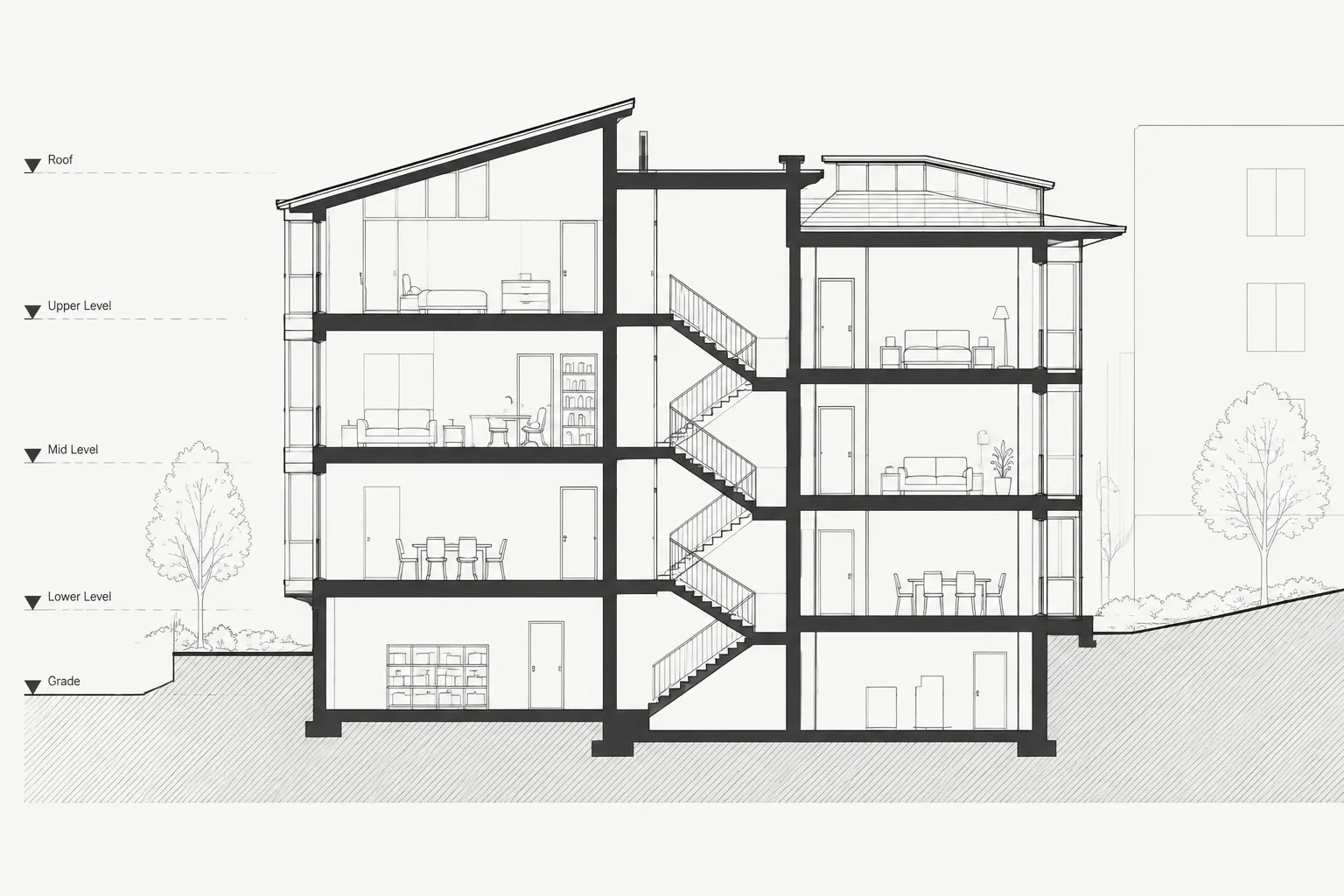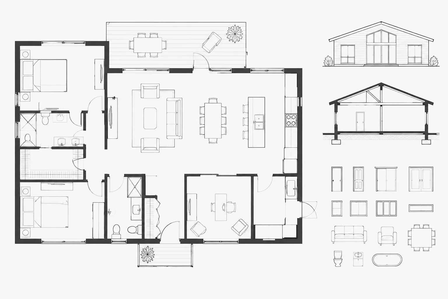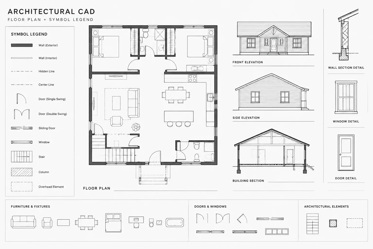
Architectural CAD legends are most useful when they reflect the symbols and terminology actually used in a drawing set. Treating the key as coordinated project information helps prevent obsolete graphics, conflicting definitions, and example tags that look like real project references.
This guide explains how to inventory symbols, organize legend content, control CAD blocks, verify plotted appearance, and maintain consistency as drawings change. It is intended as a practical workflow rather than a universal symbol standard, since graphic conventions vary among offices, disciplines, and projects.
Architectural CAD legends help readers interpret symbols, abbreviations, line conventions, materials, and graphic markers used across a drawing set. A useful legend does more than collect familiar icons. It explains the project’s actual drawing language without forcing contractors, consultants, or reviewers to search through unrelated sheets.
Legends can become unreliable when they are copied from old projects, edited independently on several sheets, or filled with symbols that never appear in the current set. The following workflow treats a legend as coordinated project information rather than decorative sheet content.
What an architectural CAD legend should communicate
A legend identifies graphic conventions that may not be self-explanatory. Depending on the project and drawing type, it may cover plan symbols, material graphics, equipment markers, accessibility-related graphics, reference markers, or discipline-specific notations.
A legend is different from a general notes list. Notes communicate instructions and requirements, while a legend explains how information is represented graphically. It is also different from a schedule, which typically organizes item-specific data into rows and columns. A symbol key may identify a sink symbol, for example, while a fixture schedule contains information associated with individual fixture types.
Common architectural legend categories include:
- Plan symbols for doors, windows, partitions, fixtures, equipment, and building elements.
- Reference symbols for sections, elevations, details, enlarged plans, and related views.
- Material symbols used in plans, elevations, sections, or details.
- Line conventions for overhead, hidden, existing, removed, or proposed work.
- Annotation markers such as room tags, wall tags, finish tags, and revision indicators.
- Project-specific symbols that are not adequately explained elsewhere.
Not every category belongs in one master legend. A concise legend placed near the relevant drawings is often easier to use than a crowded sheet containing every symbol available in an office library.
Start with the drawings, not the office template
An office template can provide a useful starting point, but it should not determine the final contents of a project legend. Begin by reviewing the symbols and graphic conventions that are actually used in the current drawing set.
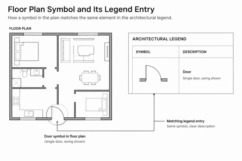
Inspect representative floor plans, reflected ceiling plans, roof plans, site drawings, elevations, sections, and details. Record symbols that may be unfamiliar, symbols that have project-specific meanings, and similar markers that could be confused with one another. This inventory reveals what needs explanation and what can be removed from a copied legend.
A practical rule is that every legend item should have a reason to be present. An unused symbol creates ambiguity because a reader may reasonably assume that it appears somewhere in the set. Removing irrelevant content makes the legend faster to scan and easier to maintain.
Choose an appropriate legend structure
The legend structure should reflect the size and organization of the drawing set. Several approaches can work:
| Approach | Best use | Coordination concern |
|---|---|---|
| Central legend sheet | Symbols shared across many architectural sheets | Readers must be directed clearly to the central location |
| Sheet-specific legend | Symbols used only in one drawing type or view | Repeated items can diverge if they are edited separately |
| Discipline or series legend | Related sheets with a consistent graphic vocabulary | Ownership must be clear when several files contribute content |
| Hybrid arrangement | Shared symbols plus specialized local symbols | Duplicate definitions should be avoided |
A hybrid arrangement is often practical: common architectural markers can be explained once, while specialized symbols remain near the plans where they are used. The important point is to avoid defining the same symbol differently in multiple locations.
Build symbols as controlled CAD content
Repeated legend graphics are good candidates for blocks because a block can keep geometry and attributes consistent. However, the block used in a legend does not always need to be identical to the working symbol placed in the plan. A plan symbol may contain attributes, masks, visibility controls, or orientation behavior that makes it awkward in a compact legend.
If separate legend blocks are created, their relationship to the working symbols should be documented and checked. Their visible appearance and terminology must agree even if their internal construction differs.
Use intentional insertion points
Set insertion points that make symbols easy to align in rows or columns. A random insertion point inherited from copied geometry makes spacing difficult and encourages manual nudging. Consistent insertion points also make it easier to replace or update legend items later.
Keep properties controlled
Assign geometry to suitable layers and use consistent property control. Unexplained object-level colors, linetypes, and lineweights can cause a legend symbol to plot differently from its plan counterpart. Check nested content as well as the block reference itself.
Avoid unnecessary detail
A legend symbol must remain understandable at its intended plotted size. Tiny construction lines, dense hatch patterns, and excessive text can merge when printed or exported. Simplify the example while preserving the characteristic graphic cues a reader needs to recognize it.
Coordinate names, abbreviations, and tags
The text beside a symbol is part of the project data. Names in the legend should match terms used in notes, schedules, tags, and specifications prepared for the project. Small variations can imply distinctions that were never intended.
Pay particular attention to:
- Singular and plural forms used inconsistently.
- Abbreviations that have more than one possible meaning.
- Legacy terminology copied from an earlier project.
- Type designations that no longer match schedules.
- Symbols renamed in plans but not in the legend.
- Similar graphics used for different purposes.
Do not assume that a symbol is universal merely because it is familiar within one office. Graphic conventions differ among firms, consultants, project types, and regions. If misinterpretation could affect plan reading, define the symbol within the set.
Separate drawing examples from project quantities
A legend is usually explanatory, not a count of installed items. The example symbol should not accidentally display a real room number, door number, type mark, or detail reference unless that value is deliberately used as a generic placeholder and cannot be mistaken for project information.
This distinction is especially important for attributed blocks. A copied working tag may retain values from the plan, causing the legend to appear to reference a real object or sheet. Review displayed attributes, hidden attributes, and default values before using such a block as an example.
Place legends for sheet readability
Legend placement should support the visual hierarchy of the sheet. Keep symbols and their descriptions aligned, leave enough white space to distinguish categories, and avoid forcing readers to follow long rows across the page.
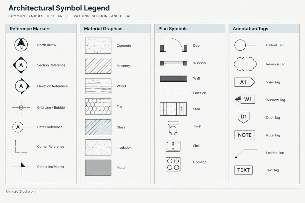
Use headings when a legend contains several families of information. For example, reference markers, material graphics, and plan symbols can be separated into clearly labeled groups. A predictable reading order is more important than filling every available gap in the title block area.
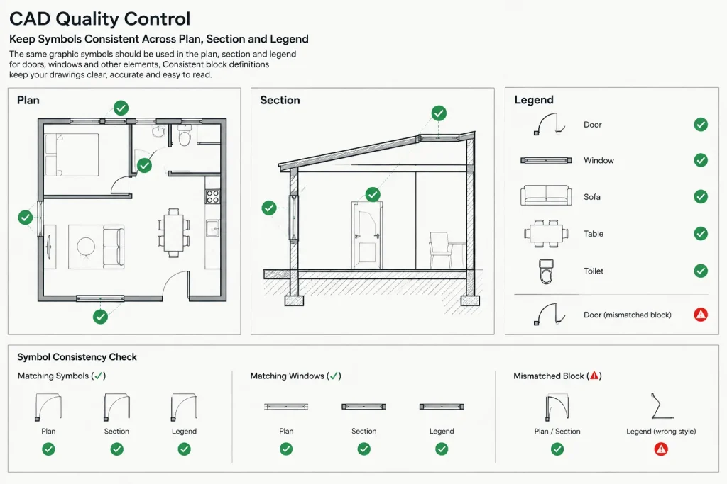
Confirm that text, hatches, lineweights, and dashed lines remain legible through the actual plotting workflow. Model-space appearance alone is not a reliable test. Review a sheet preview or exported file at a realistic viewing size.
Create a single source of truth
When the same legend is required on several sheets, avoid maintaining unrelated copies whenever possible. Depending on the project structure, the controlled source might be a referenced DWG, a shared sheet file, or a maintained block library. The specific method matters less than establishing which file is authoritative.
If local copies are necessary, assign responsibility for updating them and include legend comparisons in quality control. A copied legend should not quietly become an independent version.
Use cautious file management when sharing legend content. Referenced files should have stable names and paths, while library blocks should not be redefined casually inside active project files. Test updates in a controlled copy if a change could affect many sheets.
Quality-control checklist for CAD legends
Review legends both visually and against the drawing content before issuing a set:
- Every listed symbol is used or intentionally included for a documented reason.
- Project-specific symbols that require explanation are represented.
- Symbol graphics match their appearance in the relevant plans and details.
- Descriptions agree with schedules, notes, tags, and drawing terminology.
- No example contains an accidental project number, type value, or reference.
- Blocks do not contain stray geometry, unintended layers, or unexplained overrides.
- Hatches, dashed lines, masks, and text reproduce clearly in the plotted output.
- Duplicate legends do not contain conflicting definitions.
- Obsolete symbols from templates or previous projects have been removed.
- Changes made during revisions are reflected in the legend where necessary.
Treat the legend as part of drawing coordination
A well-managed architectural CAD legend reduces interpretation time and exposes inconsistencies in the drawings themselves. If a symbol is difficult to define clearly, its use in the plan may also be unclear. If two similar markers require lengthy explanations, their graphics may need better differentiation.
For that reason, legend preparation should begin during drawing development rather than at the end of sheet production. Maintaining a concise, project-specific key gives the team an opportunity to standardize symbols, terminology, layers, and annotation before conflicting conventions spread through the set.
Add legend review to the revision workflow
A legend can be accurate during early drafting and still become outdated after plan revisions. Symbol changes should therefore trigger a review of the related key, notes, schedules, and referenced views. This is especially important when a marker is renamed, replaced, or reassigned to a different purpose.
A simple legend register can help the team track each symbol’s description, source block, drawing location, responsible editor, and current status. The register does not need to appear on the issued sheets. It functions as an internal coordination record that makes duplicate definitions and undocumented changes easier to identify.
Review both directions
Checking only from the legend to the drawings may confirm that listed symbols exist, but it will not reveal unexplained symbols that were added later. Review in both directions: trace each legend entry to its drawing use, then scan the drawings for symbols that are absent from the key or defined elsewhere.
Distinguish graphic problems from data problems
When a symbol appears wrong, determine whether the issue comes from geometry, properties, annotation, or project data. A block may have the correct shape but the wrong label. Another may carry the correct name but plot poorly because of its layer, hatch, mask, or nested properties. Separating these causes avoids unnecessary block replacement.
Use a controlled change process
Before revising a shared symbol, identify where it is used and whether local variations exist. Confirm which file or library definition is authoritative, test the revised appearance through the normal plotting process, and communicate the change to people maintaining related sheets.
Avoid redefining a widely used block merely to correct one local example. If the required change is project-specific, consider whether a separate controlled definition is clearer than altering a library symbol used elsewhere. Names should make the relationship understandable without implying that visually similar blocks are interchangeable.
Common warning signs during quality control
- A symbol appears in the drawings but cannot be found in any relevant key.
- The same graphic has different descriptions on separate sheets.
- A legend example contains a realistic tag or reference that may be read as project data.
- Descriptions use terminology that differs from schedules or drawing notes.
- A plotted symbol loses a line, hatch, mask, or distinguishing feature.
- A copied legend contains categories unrelated to the current project.
- Several editors maintain independent copies without an identified source.
These symptoms usually indicate a coordination issue rather than a formatting issue alone. Correcting the source definition and its ownership is more reliable than repeatedly adjusting individual sheet copies.
Final coordination perspective
A symbol key should help a reader move quickly from an unfamiliar graphic to an unambiguous meaning. Concise content, controlled CAD definitions, consistent terminology, and plotted-output review all contribute to that goal. The legend is complete only when it agrees with the drawings it explains.
Frequently asked questions
What is the difference between a CAD legend and a symbol key?
The terms are often used interchangeably. A symbol key usually focuses on identifying graphic markers, while a broader legend may also explain abbreviations, materials, line conventions, hatches, and annotation types.
Should every architectural sheet have its own legend?
Not necessarily. Shared conventions can be defined in a central location, while specialized symbols may be explained near the drawings that use them. The best arrangement is the one that makes definitions easy to find without creating conflicting copies.
Should unused symbols remain in a project legend?
Unused symbols generally create uncertainty because readers may assume they occur somewhere in the set. Retain an unused item only when the project team has a documented reason for including it.
Can the same block be used in both a plan and its legend?
Yes, when it remains clear and manageable in both contexts. A separate legend block may be appropriate if the working block contains attributes, masks, orientation behavior, or other content that is not useful in the key. The visible graphics and terminology should still agree.
Why can a legend look correct in CAD but fail in the issued drawing?
Screen display may not reveal problems caused by plotting, export, lineweight, linetype, hatch density, masks, or nested block properties. Review the legend through the same output process used for the drawing set.
Who should maintain the architectural CAD legend?
The project team should identify an owner or authoritative source rather than allowing unrelated copies to evolve independently. Responsibility may follow the project’s file structure, sheet organization, or discipline workflow.