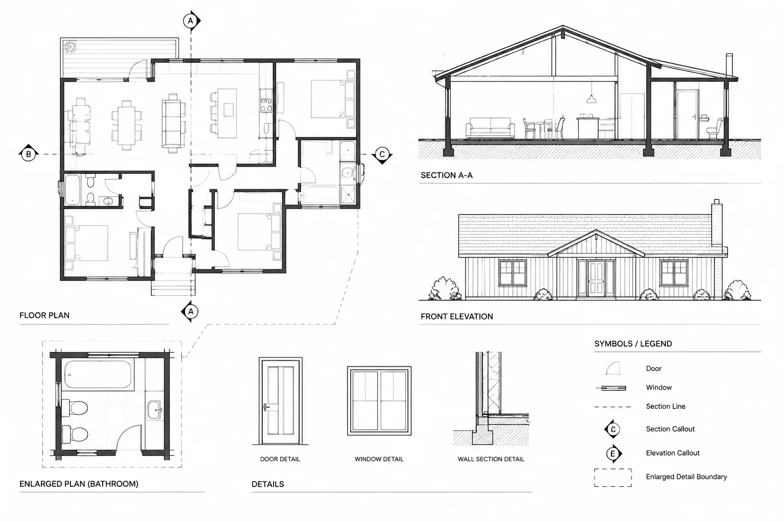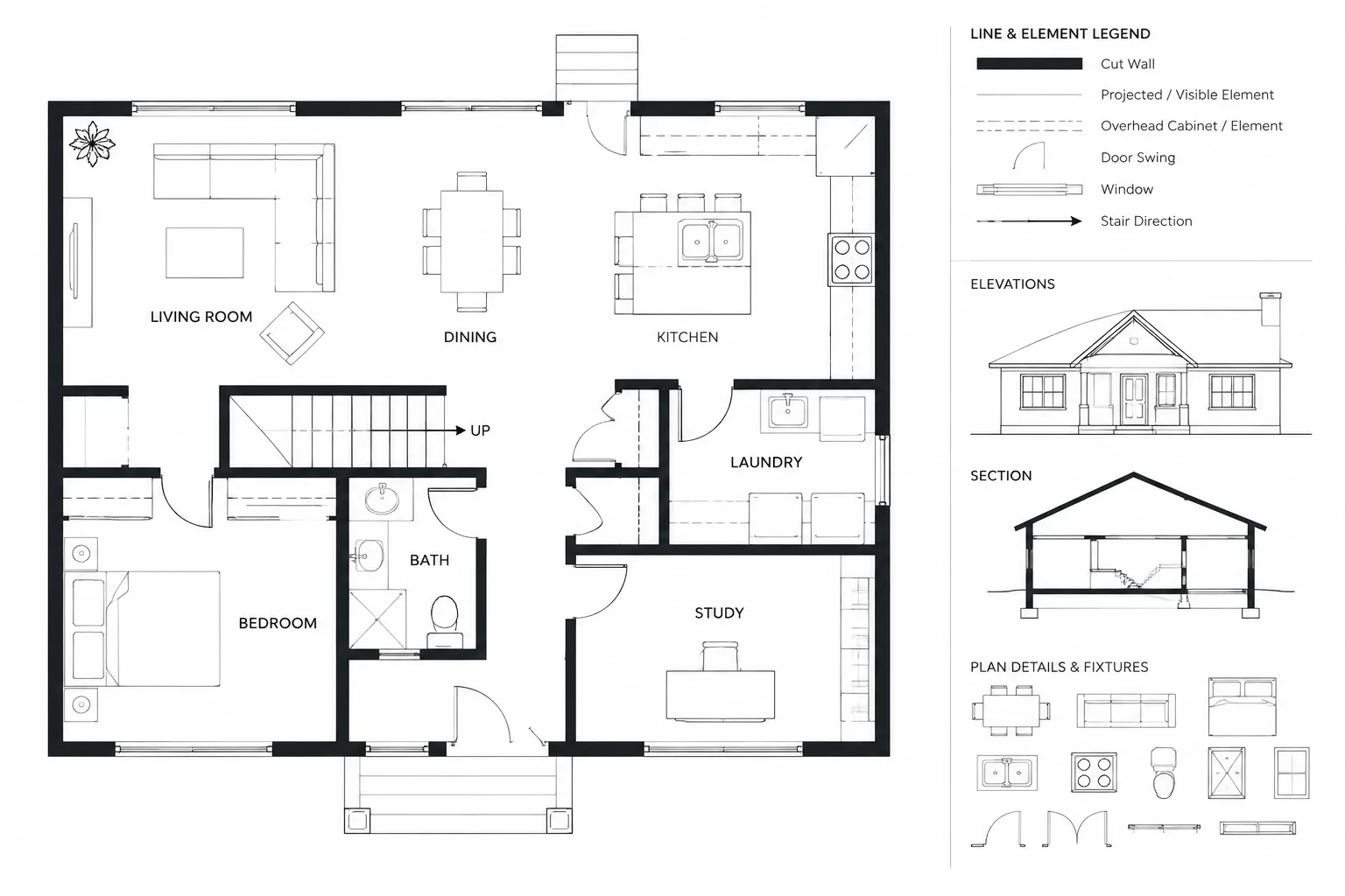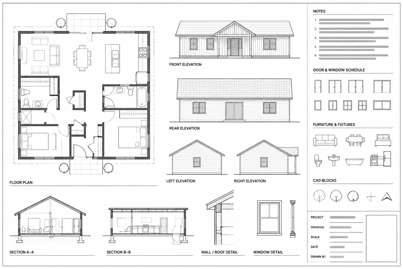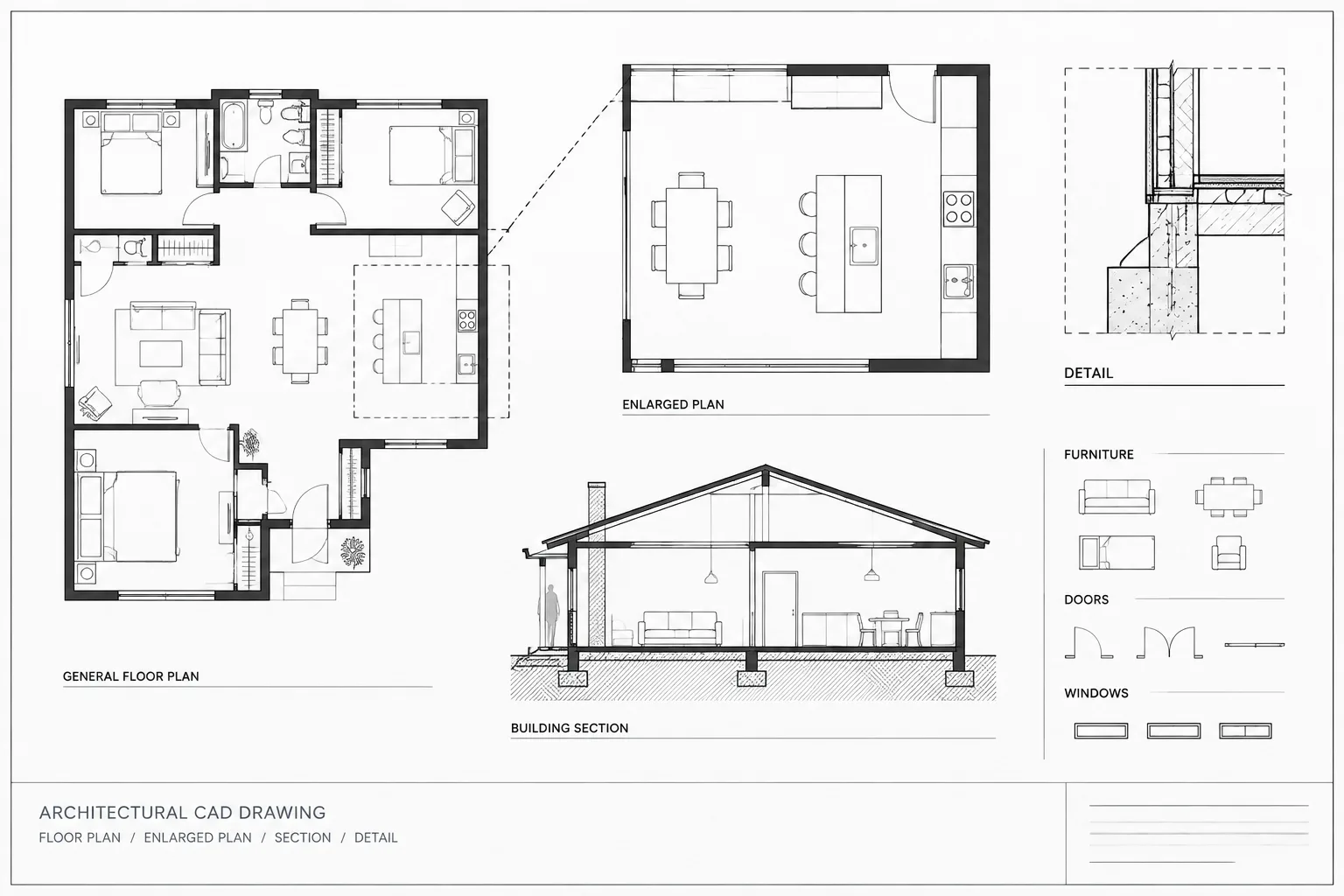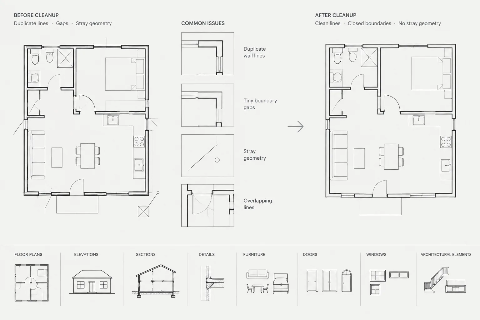
Architectural CAD geometry cleanup begins with diagnosis, not deletion. The same visual symptom can come from duplicate linework, an open boundary, a damaged block, imported content, or intentional coordination graphics. This guide explains how to distinguish those conditions, repair the underlying geometry, and verify that the DWG still communicates the design correctly.
A floor plan can look clean on screen while still containing duplicate lines, tiny gaps, distant objects, fragmented polylines, and unnecessary definitions. These problems may remain unnoticed until someone edits the plan, applies a hatch, measures an area, creates a PDF, or shares the DWG with a consultant.
Architectural CAD geometry cleanup is not simply a matter of making a file smaller. The goal is to make the drawing predictable. Walls should trim correctly, room boundaries should close, selections should behave logically, and plotted graphics should reflect the intended hierarchy. Cleanup should preserve meaningful architectural information while removing accidental clutter.
Why geometry problems develop
Most drawing contamination is cumulative. A file may pass through several project phases, team members, consultant backgrounds, and imported references. Each operation can introduce small inconsistencies.
- Copying geometry in place can create exact duplicates.
- Tracing imported PDFs or consultant files can leave overlapping segments.
- Repeated trimming may create very short line fragments.
- Blocks may contain hidden or distant objects that affect their extents.
- Exploded content can turn organized objects into disconnected geometry.
- Walls and room outlines may appear connected while retaining small endpoint gaps.
- Unused layers, blocks, linetypes, and text styles can accumulate through copying and insertion.
Not every overlap is an error. A visible line may intentionally coincide with a hatch boundary, viewport clipping edge, masking object, or another discipline’s reference. Cleanup therefore requires inspection and judgment rather than indiscriminate deletion.
Start with a protected working copy
Perform substantial cleanup in a copy of the drawing, especially when the DWG came from another project participant. Retain the original file as a reference so that deleted or altered information can be recovered.
Before changing geometry, identify the file’s role. A live architectural model file, a consultant background, a detail-library source, and an archival record should not all be treated the same way. If the file is externally referenced into other drawings, changing layer names, block definitions, coordinates, or object structure may affect downstream sheets.
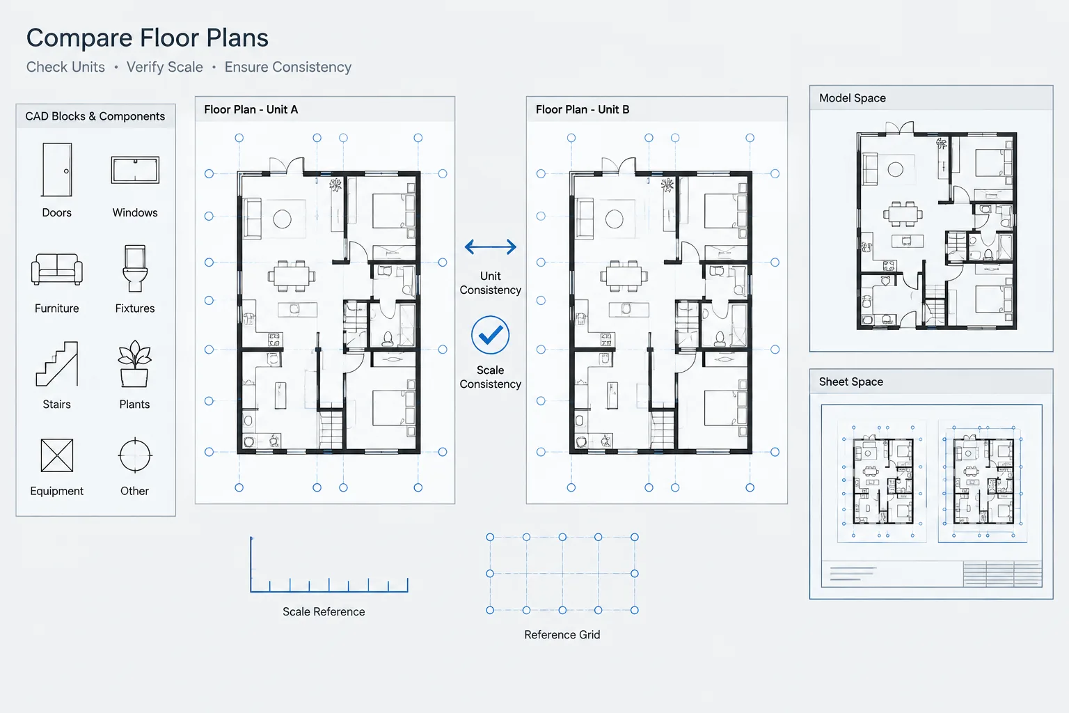
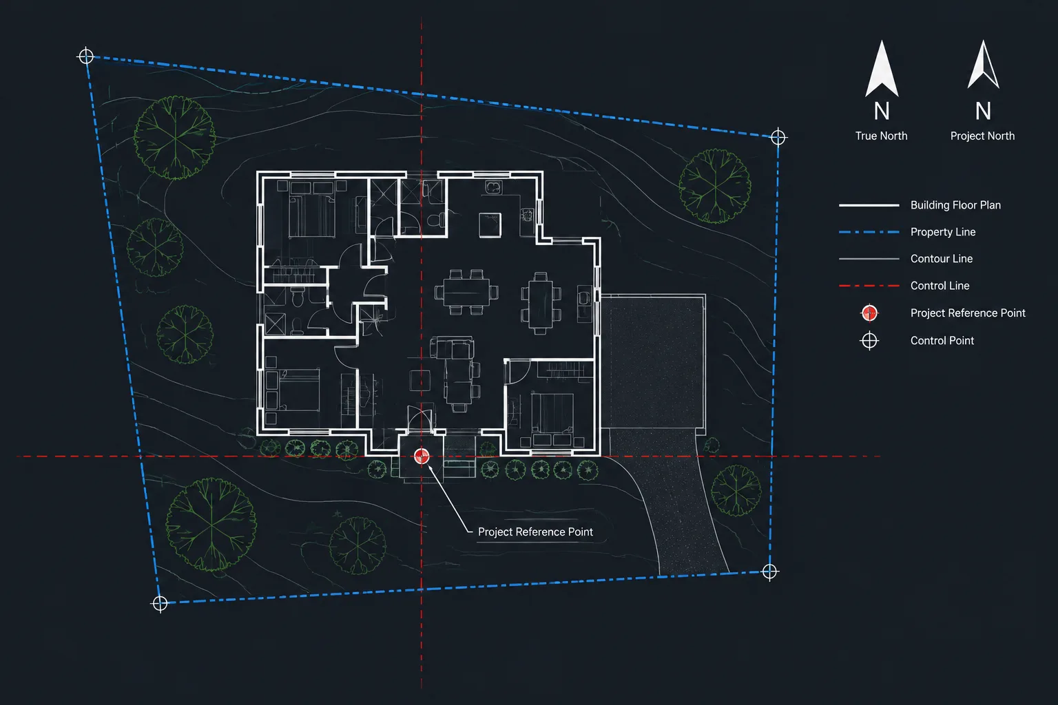
Confirm the drawing units and project location before interpreting unusual geometry as an error. A distant survey point or project control marker may be intentional. Likewise, geometry that appears far from the building may belong to a site reference, alternate design study, or temporary coordination area.
Inspect the drawing before running cleanup commands
Review the overall extents
Use an extents view to see whether the visible project occupies only a small portion of the drawing area. If it does, inspect the distant regions rather than deleting them immediately. Stray text, points, block components, dimensions, and construction lines can all expand the apparent drawing extents.
Layers can be isolated in logical groups to narrow the search. Check annotation, dimensions, reference geometry, site information, and architectural model layers separately. Objects inside blocks or external references may require inspection within their source rather than editing from the host drawing.
Look for visual warning signs
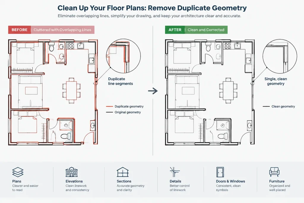
Duplicate or fragmented geometry often reveals itself during ordinary drafting. Watch for lines that appear unusually heavy despite using the expected layer and lineweight, objects that require multiple deletion attempts, hatches that fail to recognize an apparently enclosed area, and grips that expose several endpoints where only one should exist.
Selection cycling or similar object-selection tools can help reveal coincident objects. Temporarily changing object colors by layer, freezing hatch layers, or turning off dense annotation can also make the underlying linework easier to evaluate.
Clean exact duplicates and overlapping segments carefully
AutoCAD’s duplicate-object cleanup tools can compare selected linework and remove or combine geometry according to chosen settings. These tools are useful, but the selection area matters. Begin with a controlled portion of the plan instead of processing the entire project without review.
Pay particular attention to wall faces, grid lines, door frames, casework outlines, and imported details. A cleanup operation may interpret aligned segments as redundant even when their layer, color, linetype, or purpose differs. Settings that ignore object properties can produce unexpected results.
A safer process is to test the operation in a representative area, compare the result with the original, and then expand the scope. Afterward, verify that dashed overhead elements, demolition graphics, rated assembly lines, and other intentionally coincident information remain intact.
Repair small gaps and fragmented boundaries
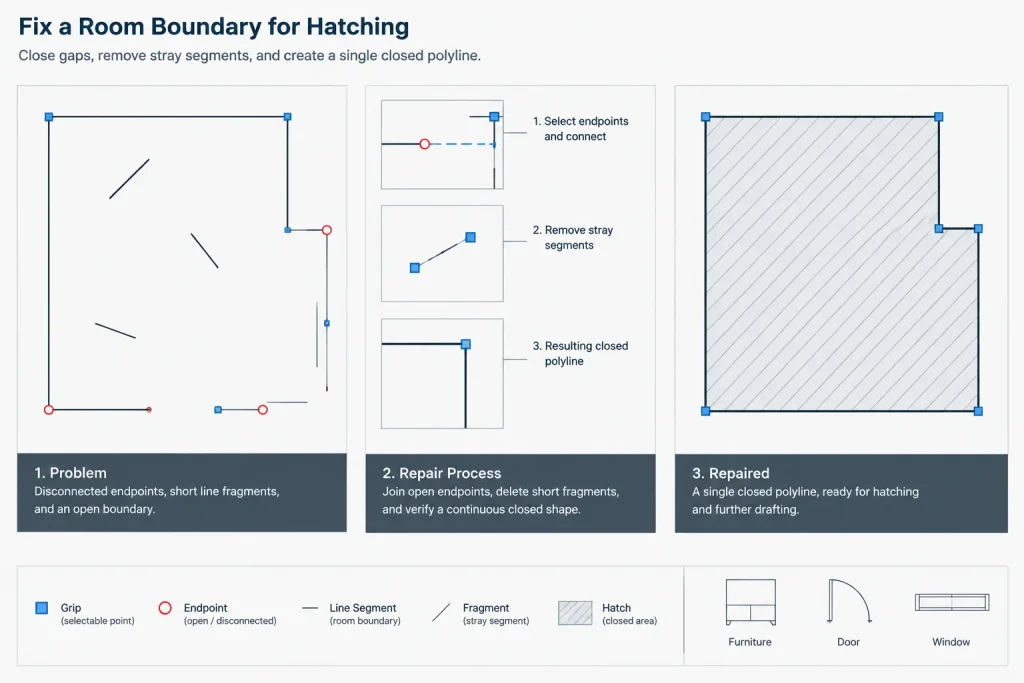
Small endpoint gaps can interfere with hatching, area calculations, room boundaries, offsets, and later editing. Rather than drawing extra bridging lines over a problem, inspect the endpoints and repair the underlying geometry.
- Use object snaps to check whether endpoints truly meet.
- Trim or extend lines to a clear intersection.
- Join compatible segments when a continuous polyline is useful.
- Remove short fragments left behind by previous trimming.
- Rebuild badly fragmented outlines when repair would be less reliable.
Do not apply one universal gap tolerance to every file. An acceptable tolerance depends on the drawing units, project scale, intended output, and the type of geometry being repaired. A setting appropriate for a site boundary may be unsuitable for a small architectural detail.
Closed polylines are especially useful for room areas, floor finishes, demolition limits, and hatch boundaries. However, converting every line into a polyline is unnecessary. Use continuous objects where they support a specific drafting or coordination purpose.
Investigate blocks, hatches, and external references
Blocks
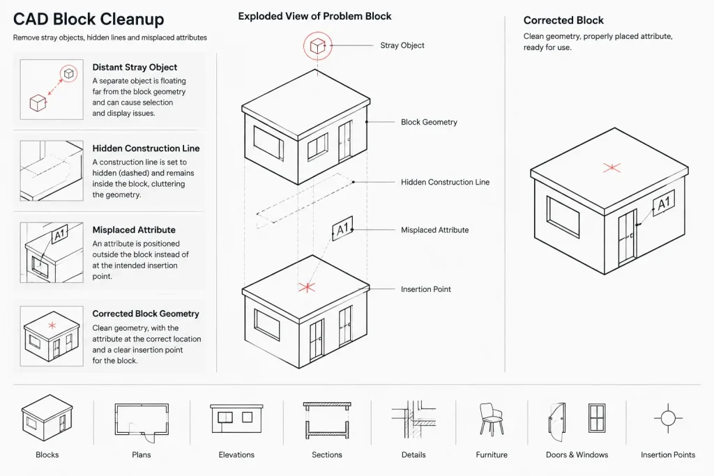
A block can appear correct while containing duplicate components, misplaced attributes, hidden construction lines, or an accidental object far from its insertion point. If several block instances create the same graphical problem, inspect the block definition rather than editing each insertion.
Confirm that the block’s internal layers and properties are intentional. Avoid flattening a useful block into raw geometry merely to simplify one edit. Exploding blocks can multiply objects and remove the consistency that made the block valuable.
Hatches
Dense or duplicated hatches can make selection difficult and increase file complexity. Determine whether apparently overlapping hatches represent separate materials, phases, or drawing conventions before deleting them. If a hatch has lost its boundary relationship, consider whether recreating a clean boundary and hatch is more dependable than repeatedly patching the existing object.
External references
Do not clean referenced consultant information by editing around it in the architectural host file. Identify whether the problem belongs to the source reference, an overlay created for coordination, or architectural geometry drawn over the reference. Keep any project-specific cleanup copy clearly identified so that it is not mistaken for the consultant’s current deliverable.
Separate geometry cleanup from file maintenance
Geometry cleanup and database maintenance are related, but they solve different problems. Removing unused definitions can reduce clutter in layer, block, linetype, and style lists. Drawing-audit tools can identify certain database inconsistencies. Neither operation guarantees that architectural linework is correct.
| Task | Primary purpose | What still requires review |
|---|---|---|
| Duplicate-object cleanup | Find coincident or overlapping geometry | Intentional overlaps and property differences |
| Join or polyline editing | Create continuous boundaries | Correct path, closure, and architectural meaning |
| Purge unused definitions | Remove unreferenced file content | Standards resources that may be needed later |
| Drawing audit | Check aspects of DWG database integrity | Graphic accuracy and project coordination |
| Manual visual review | Confirm the architectural result | All sheet views and plotted output |
Purging should be deliberate. A project template or active production file may intentionally retain standard layers, blocks, and styles for future use. Removing everything unused can force the team to recreate or reimport approved office resources.
Validate the cleaned drawing
After cleanup, repeat the tasks that originally exposed the problem. Test representative hatches, measure important boundaries, select edited wall lines, and inspect blocks. Regenerate the drawing and review model-space extents. If the file is used on sheets, open those sheets and confirm that references load and viewports still display correctly.
Create a test PDF using the project’s normal plotting configuration. Screen display alone may not reveal coincident lines, masking conflicts, unintended lineweights, or broken dashed patterns. Compare the test output with an earlier issue or the protected original where appropriate.
A practical cleanup sequence
- Save a protected copy and identify the drawing’s role.
- Confirm units, coordinates, references, and expected project extents.
- Inspect distant objects and suspicious layer groups.
- Test duplicate-object cleanup on a limited selection.
- Repair gaps, fragments, and boundaries by architectural element.
- Inspect repeated problems inside block definitions.
- Review hatches and references without erasing meaningful information.
- Audit the file and selectively remove unused content if appropriate.
- Recheck sheets, viewports, dimensions, areas, and plotted output.
- Document significant changes when the cleaned file will be shared.
A dependable architectural DWG is not necessarily one with the fewest objects. It is one in which each object has a clear purpose, boundaries behave as expected, and the drawing can be edited and plotted without surprises. Careful geometry cleanup supports faster drafting, more reliable coordination, and a cleaner handoff to everyone who uses the file next.
Use drawing behavior to guide the investigation
When a plan behaves unexpectedly, start with the affected task and work backward. This reduces the risk of applying broad cleanup operations to geometry that is already correct.
- A hatch will not fill: inspect boundary endpoints, intersections, short fragments, and the intended enclosure.
- An area result seems unreliable: confirm that the measured boundary follows the correct architectural edge and forms a continuous enclosure.
- A line looks unexpectedly bold: check for coincident objects before changing its layer or graphic properties.
- The drawing opens at an unusually broad extent: inspect distant geometry, block contents, references, and project control information.
- Editing feels unpredictable: look for stacked objects, fragmented segments, inconsistent object types, and geometry embedded in blocks.
- The PDF differs from the screen view: review overlapping linework, masking relationships, hatches, linetypes, and plot-dependent graphics.
Document cleanup decisions for the next user
Cleanup becomes part of project coordination when the DWG is shared. Record significant changes such as removed distant geometry, repaired room boundaries, revised block definitions, or retained overlaps that were confirmed as intentional. A brief note helps the next drafter understand what changed without having to rediscover the original problem.
Where uncertainty remains, preserve questionable content in the protected working copy rather than forcing a permanent decision. The best cleanup process improves reliability while keeping the design history and coordination context recoverable.
Frequently asked questions
Why can a clean-looking floor plan still contain CAD errors?
Several objects can occupy the same visible location, and very small endpoint gaps may be difficult to see at a normal viewing scale. Hidden block content, distant objects, fragmented lines, and unused definitions can also remain unnoticed until the drawing is edited, measured, hatched, plotted, or referenced.
Should every overlapping line be deleted?
No. Coincident geometry may represent different layers, phases, materials, disciplines, hatch boundaries, masking elements, or graphic conventions. Compare object properties and architectural purpose before removing anything.
Why does a hatch fail when the room appears enclosed?
The apparent enclosure may contain an endpoint gap, an overshooting segment, a short fragment, or an intersection that does not connect as expected. Inspect and repair the underlying boundary rather than covering the problem with extra linework.
Is purging the same as cleaning geometry?
No. Purging addresses unused definitions, while geometry cleanup addresses the objects that form and describe the drawing. A file can have tidy definition lists and still contain duplicates, gaps, fragments, or misplaced objects.
Should blocks be exploded during cleanup?
Not automatically. Exploding can remove useful organization and multiply loose geometry. When a repeated problem appears in several block instances, inspect the block definition and correct it only after confirming that the change is appropriate for every use.
How can stray objects be distinguished from project control geometry?
Review the drawing’s coordinate strategy, layer organization, references, and intended site information. A remote point or line may support survey control, project location, coordination, or an alternate study. Confirm its purpose before deleting it.
How should a cleaned DWG be checked before sharing?
Repeat the operation that exposed the issue, inspect the drawing extents, review affected blocks and boundaries, open dependent sheets, and create a test plot using the normal project workflow. Compare the result with the protected original when necessary.