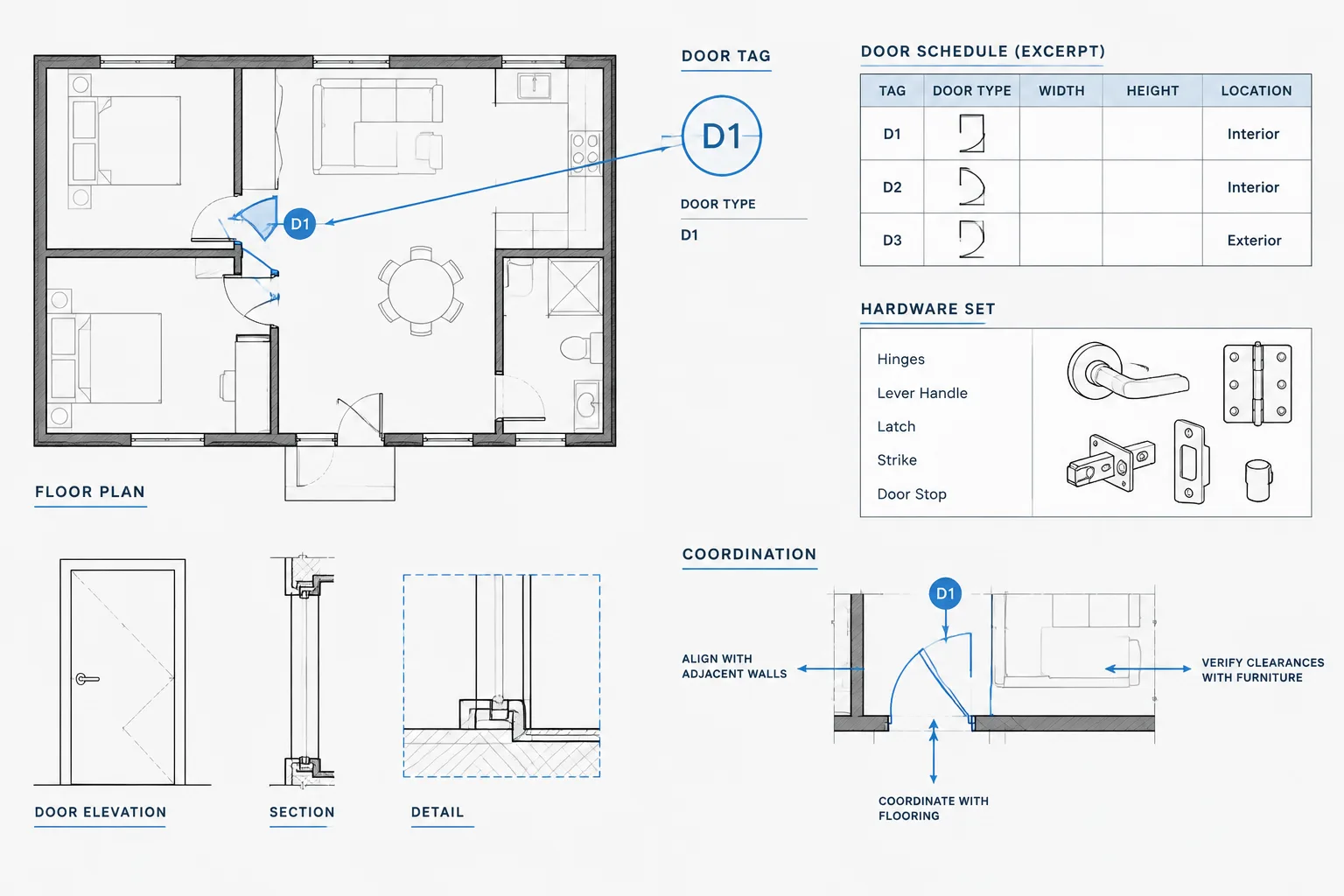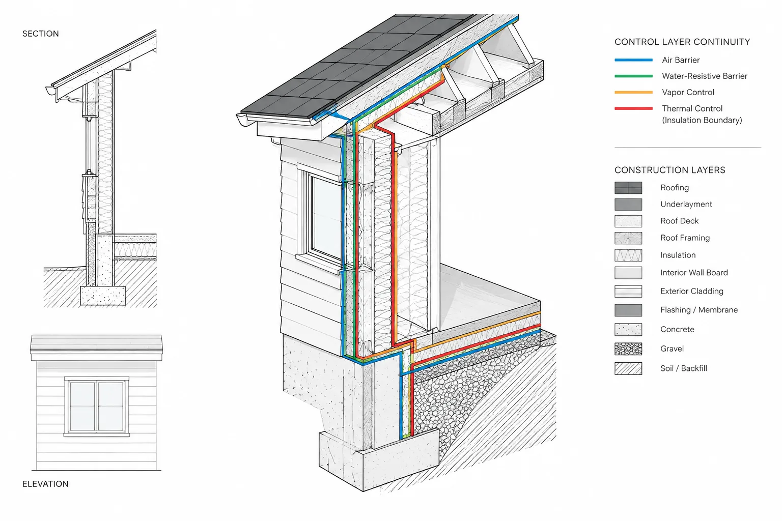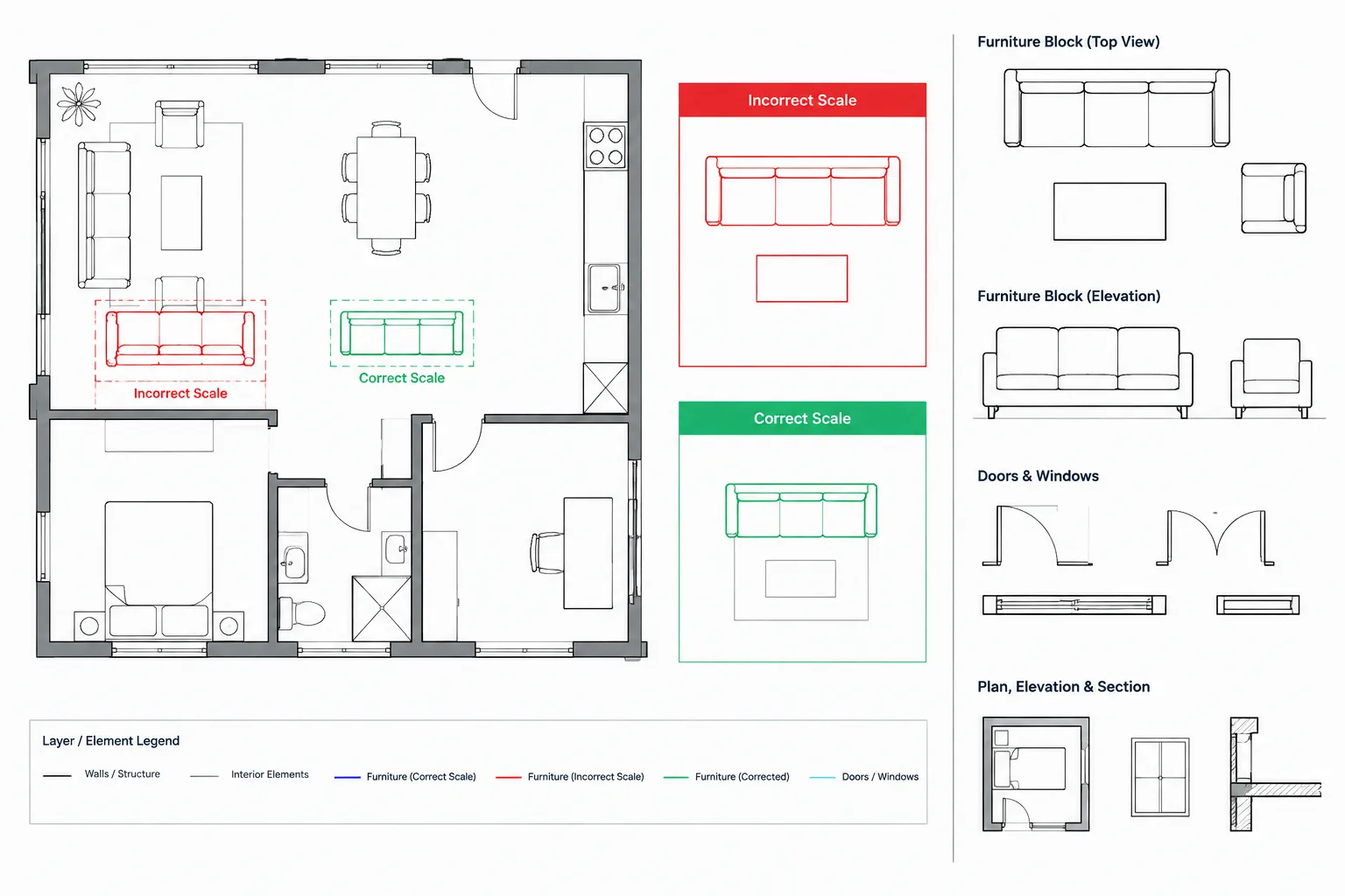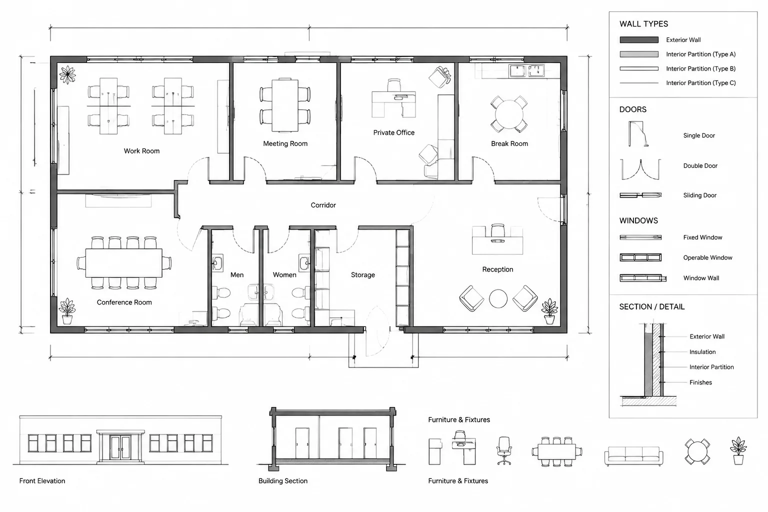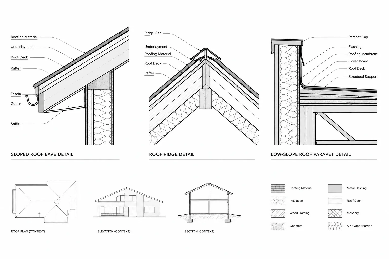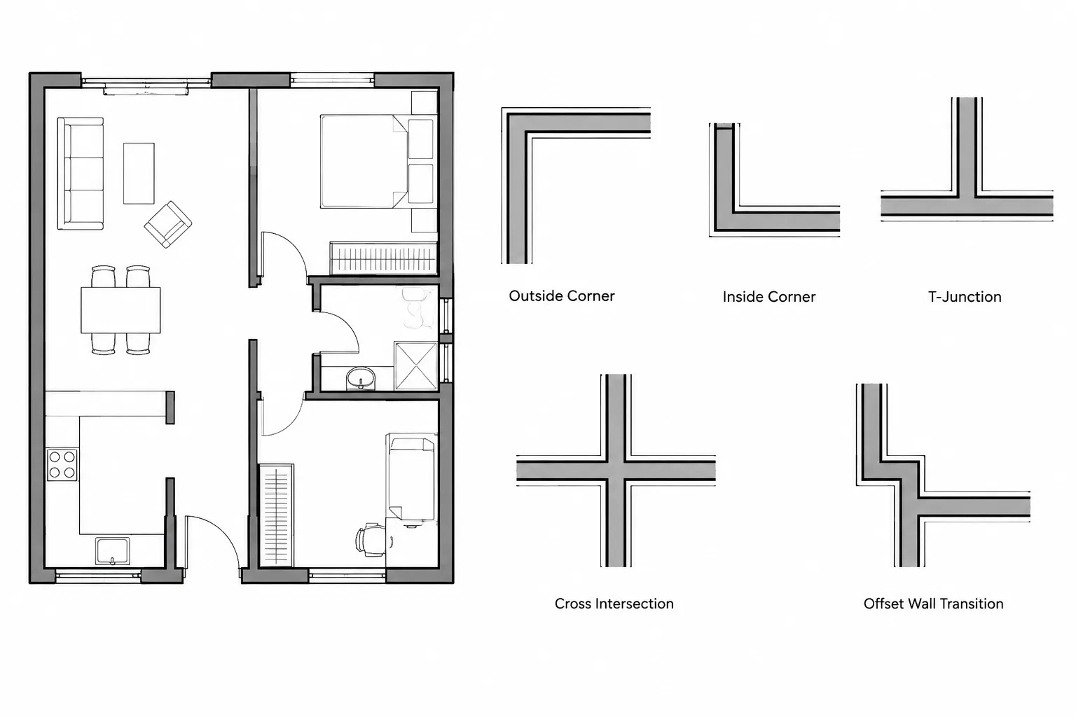
Wall intersections in architectural CAD must do more than look tidy on screen. Each junction should preserve the intended wall alignment, communicate continuity, remain easy to revise, and reproduce clearly in the plotted drawing.
This guide explains how to evaluate corners, T-junctions, cross intersections, offsets, and curved connections without using graphic cleanup to invent construction intent. It also provides a practical framework for distinguishing faulty geometry from a scale, hatch, layer, or draw-order problem.
Wall intersections are among the most common sources of small but consequential errors in architectural floor plans. A corner may look acceptable at one zoom level while concealing overlapping lines, an open boundary, or an incorrect material relationship. T-junctions can obscure which wall continues, and crowded intersections can become unreadable when hatches, dimensions, door openings, and consultant backgrounds are added.
A reliable workflow for wall intersections in architectural CAD should address more than line cleanup. It should communicate wall continuity, preserve usable geometry, support later revisions, and produce a clear plot. The correct graphic treatment depends on the wall assemblies and construction intent, so CAD cleanup should follow the project information rather than assumptions about how walls are built.
Why Wall Intersections Need Deliberate Drafting
Walls are often drawn as pairs of parallel lines, but an architectural wall is not simply a graphic band. It may represent finish layers, substrates, framing or masonry, cavities, fire-resistance requirements, structural elements, and exterior cladding. Not every layer necessarily continues through an intersection.
A clean intersection helps the reader understand:
- Which wall continues and which wall terminates.
- Whether materials wrap, stop, align, or change.
- Whether the condition is a corner, partition junction, shaft enclosure, or wall transition.
- Where dimensions and room boundaries should terminate.
- Whether a larger-scale plan, section, or detail is needed.
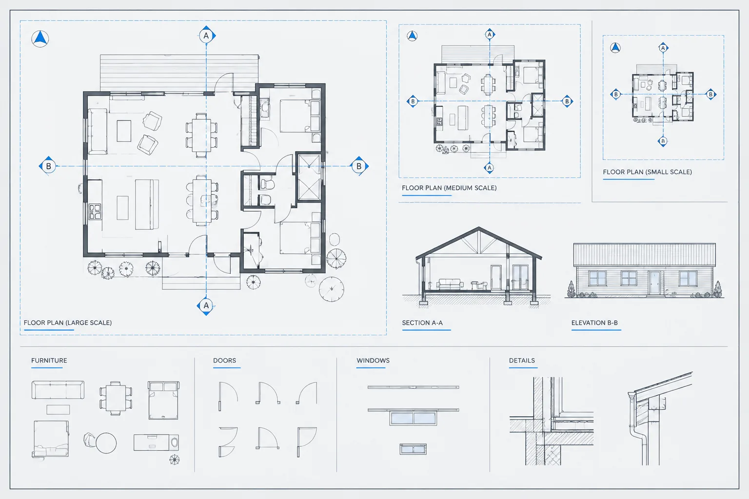
Plan graphics should remain appropriately simplified for their drawing scale. A general floor plan may show only the dominant wall boundaries, while an enlarged plan or detail can explain individual layers and closure conditions.
Start with a Consistent Wall Construction Method
Before cleaning intersections, determine how walls are being represented in the file. Common methods include separate linework for each face, polylines outlining the full wall, centerlines with offsets, or intelligent wall objects in software that supports them. Mixing methods without a clear reason can make intersections difficult to maintain.
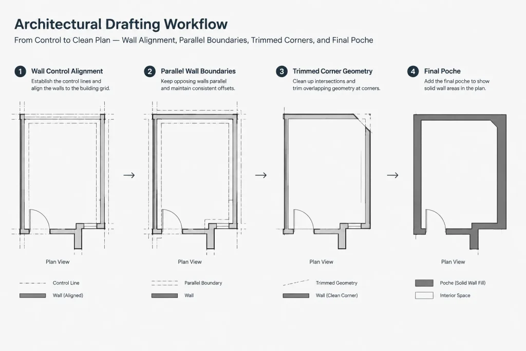
For conventional two-dimensional drafting, a practical sequence is:
- Establish the controlling wall alignment, such as a face, centerline, or grid relationship.
- Create the parallel boundaries from that control geometry.
- Resolve corners and junctions before adding detailed poche or hatch.
- Insert openings only after the wall geometry is stable.
- Apply annotation and dimensions after the main intersections have been checked.
Do not switch casually between dimensioning to wall faces and dimensioning to centerlines. The selected control method should reflect project practice and the information needed for coordination.
Drafting Common Wall Intersection Types
Outside and Inside Corners
At a simple corner, corresponding wall boundaries should meet without visible gaps or unnecessary extensions. Use trim, extend, or other precise editing tools rather than relying on visual placement. If the walls have several represented layers, decide which layers turn the corner and which terminate.
For an outside corner, verify that the exterior outline reads as one continuous perimeter. For an inside corner, remove short line fragments that can become dark spots when plotted. Avoid using a heavy cover line merely to conceal unresolved geometry underneath.
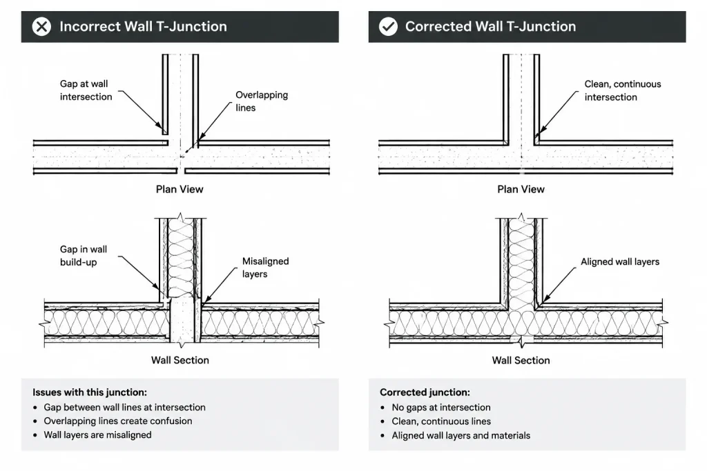
T-Junctions
A T-junction occurs when one wall terminates against another. The continuous wall should generally remain visually legible, while the terminating wall should meet it cleanly. This does not mean every internal component automatically stops at the same location. Finish layers, structural components, and enclosure requirements may create a more complex condition.
Check both faces of the terminating wall. A frequent error is to connect one side correctly while leaving the other side slightly short, extended, or snapped to the wrong wall layer. If the junction is close to a door opening, verify that the wall end and opening jamb have not been merged accidentally.
Cross Intersections
Where walls cross, the plan can become visually dense. First determine whether the condition is truly four-way or whether it represents two T-junctions with different material relationships. Establish the dominant continuous geometry before trimming the secondary boundaries.
At a small drawing scale, excessive internal lines can create an unreadable knot. Show only the information appropriate to the plan and use a larger-scale reference when the assembly relationship matters.
Offset and Misaligned Intersections
Walls do not always meet on matching centerlines or faces. Offset partitions, changing wall thicknesses, column enclosures, and finish transitions can produce stepped junctions. Do not force these into a false symmetrical connection for graphic neatness.
Retain the controlling alignment and draw the transition explicitly. A short return, reveal, pilaster, or change in wall face may be intentional. If the reason for an offset is uncertain, flag it for coordination rather than smoothing it away.
Angled and Curved Junctions
Angled walls require accurate intersections between the actual boundary lines. Avoid approximating the meeting point by eye. Curved walls need particular attention because offsets may behave differently at tight changes in direction, and imported curves may consist of many short segments.
Inspect curved junctions at a close zoom, but also review them at the intended plot scale. A mathematically precise connection can still produce poor graphics if several edges converge into a dark cluster.
Separate Geometry Problems from Graphic Problems
Some intersections are geometrically wrong; others are geometrically correct but graphically unclear. Treat these as different issues.
| Condition | Likely issue | Recommended response |
|---|---|---|
| Visible gap between boundaries | Lines do not share an endpoint | Extend or redraw using precise object snaps |
| Dark spot at a corner | Overlapping or duplicate linework | Remove duplicates and short hidden fragments |
| Wall hatch leaks into another area | Boundary is open or overlapping | Repair the enclosing geometry before rehatching |
| Continuous wall appears interrupted | Incorrect trimming or draw order | Restore the controlling edge and review masking objects |
| Junction looks crowded when plotted | Too much detail for the view scale | Simplify the plan representation and reference a detail |
| Wall faces shift after revision | No consistent control alignment | Reestablish the intended face, centerline, or grid control |
Use Layers to Preserve Editing Control
Keep wall outlines, overhead information, demolition work, hatches, and annotations on appropriate layers. Do not place small corrective lines on an unrelated layer simply because it plots with the desired weight. That shortcut makes later editing and layer-state control unreliable.
If separate wall components are shown, organize them according to the project layer system. A consistent layer structure allows the drafter to isolate the primary boundaries, clean intersections, and then restore finishes and poche for review.
Temporary construction geometry should be removed or placed on a nonplotting working layer managed according to office practice. Do not leave alignment lines embedded in the finished wall graphics.
Coordinate Hatches and Poché After Geometry Cleanup
Hatch should reinforce wall hierarchy, not conceal drafting mistakes. Apply or update it after wall boundaries are closed and intersections are resolved. Associative behavior can help during revisions, but it does not eliminate the need to inspect the resulting boundary.
At junctions between different wall types, verify whether the graphic fill should continue, change, or stop. A hatch boundary is not proof of a construction relationship. The underlying wall-type information and details remain the controlling sources.
Also check that poche does not cover door swings, tags, dimensions, or important edges. Where masks are used for annotation, review draw order carefully so the wall remains understandable.
Check Openings Near Intersections
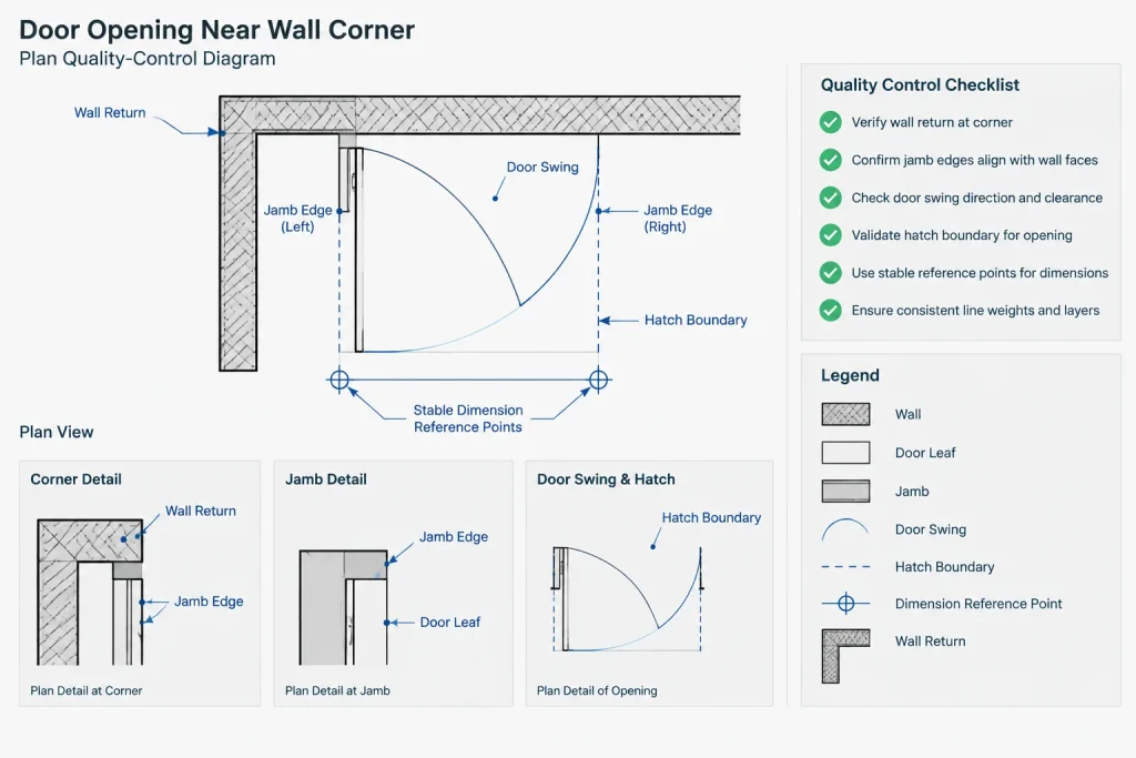
Doors and windows positioned close to corners or T-junctions require extra attention. The opening may leave a short wall return that is easy to delete accidentally. Door frames, casing, and swing graphics can also obscure the true wall endpoint.
When reviewing these conditions:
- Temporarily hide door swings and annotation to inspect the wall geometry.
- Confirm that the opening cuts only the intended wall boundaries.
- Check whether the jamb condition requires an enlarged plan or detail.
- Verify that dimensions reference stable architectural geometry rather than a swing arc or hatch edge.
- Review adjacent room boundaries after moving the opening.
A Practical Cleanup and Quality-Control Pass
Wall intersection review is most effective when performed systematically rather than only where a problem is visible. Isolate the architectural wall layers and move through the plan in a consistent direction. Review perimeter corners first, followed by major corridor walls, room partitions, shafts, and small enclosure conditions.
For each intersection, ask:
- Do the intended boundaries meet at exact endpoints?
- Are any duplicate lines stacked in the same location?
- Is wall continuity clear?
- Does the junction agree with the wall types and available details?
- Are hatches contained correctly?
- Have nearby openings, dimensions, and room boundaries updated?
- Does the condition remain clear in the plotted sheet view?
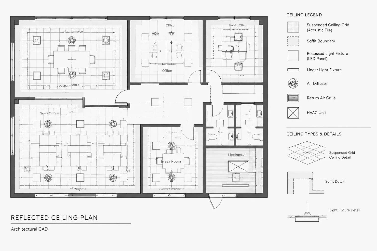
Finish by comparing the plan with related reflected ceiling plans, elevations, sections, structural backgrounds, and enlarged plans. A clean floor-plan intersection can still be wrong if it conflicts with a column, ceiling condition, exterior articulation, or construction detail.
When to Stop Drafting and Request Coordination
CAD linework should not be used to invent an unresolved construction condition. If drawings disagree about wall continuity, assembly thickness, structural support, enclosure requirements, or finish returns, record the issue for the appropriate project decision-maker.
The goal is not merely to create perfect-looking corners. A well-drafted wall intersection communicates the available design information honestly, remains editable, and directs the reader to more detailed information when necessary. Clean geometry, disciplined layers, restrained graphics, and a repeatable review process make even complex plans easier to coordinate and revise.
A Decision Order for Ambiguous Wall Junctions
When an intersection is unclear, avoid beginning with trim commands or cover-up graphics. First identify the information that controls the condition. A useful review order is construction intent, wall alignment, represented components, plan-scale graphics, and annotation coordination.
Confirm the Construction Relationship
Determine whether the intersecting elements are the same wall type, different assemblies, finish-only returns, structural enclosures, or partitions terminating against another element. If the available drawings do not answer that question, the junction requires coordination rather than an improvised CAD solution.
Identify the Controlling Geometry
Establish which face, centerline, grid, or other project reference governs the wall location. This helps prevent a visually clean edit from shifting a dimensioned room edge, corridor alignment, exterior face, or consultant coordination point.
Choose the Appropriate Level of Representation
After the geometry is understood, decide what belongs in the current view. A floor plan should communicate the junction clearly without carrying every assembly layer into a scale where those lines merge. More detailed material relationships can be reserved for an enlarged plan, section, or construction detail.
Revision Habits That Protect Wall Geometry
- Edit from stable references: Move or rebuild walls from established control geometry rather than from hatch edges, masks, or annotation.
- Inspect connected conditions: A wall edit can affect nearby openings, room boundaries, finish returns, dimensions, and references in related views.
- Regenerate graphic fills: Review hatch and poche after changing the enclosing linework instead of assuming they remain accurate.
- Check with presentation layers restored: Geometry may appear correct in isolation but become unclear when furniture, dimensions, tags, and consultant information are visible.
- Review the plotted result: Screen zoom can reveal drafting defects, while the sheet view reveals whether lineweight and graphic density communicate the condition successfully.
What a Finished Intersection Should Communicate
A completed junction should let the reader recognize the continuous wall, the terminating or returning element, and any meaningful change in material or alignment. It should also remain composed of dependable geometry that can support hatches, room boundaries, dimensions, and later revisions.
If that information cannot be communicated at the plan scale without crowding, simplify the plan graphic and direct the reader to a more detailed view. Clarity is preferable to adding linework that appears precise but does not resolve the underlying condition.
Frequently Asked Questions
Should the continuous wall always remain unbroken at a T-junction?
The plan should make continuity understandable, but the exact treatment depends on the assemblies being represented. Finishes, substrates, structural components, and enclosure layers may terminate or continue differently. Follow the project wall types and details rather than applying one graphic rule to every junction.
Why does a wall corner look dark when the geometry appears closed?
A dark corner often results from duplicate lines, short overlapping fragments, dense hatch, or several edges converging in a small area. Isolate the primary wall boundaries, remove unnecessary geometry, and review the result with the intended lineweights and fills restored.
Can hatch be used to close a small gap in a wall intersection?
No. Hatch can disguise a gap without repairing the boundary used by other drawing elements. Correct the wall geometry first, then update or recreate the fill and confirm that it remains contained.
How should a wall junction near a door be checked?
Temporarily reduce the visual clutter from swings, tags, and dimensions so the wall return and jamb can be inspected directly. Confirm that the opening affects only the intended boundaries and that nearby dimensions reference stable architectural geometry.
When should an intersection be shown in a separate detail?
Use a larger-scale view when assembly layers, closures, finish returns, structural relationships, or other construction information cannot be communicated clearly in the general plan. The plan can remain simplified while still identifying the location of the detailed condition.
What should be done when plans and sections show different wall relationships?
Do not select the version that produces the cleanest plan graphic. Record the discrepancy and coordinate it with the appropriate project team member. CAD cleanup should document an agreed condition, not conceal conflicting information.