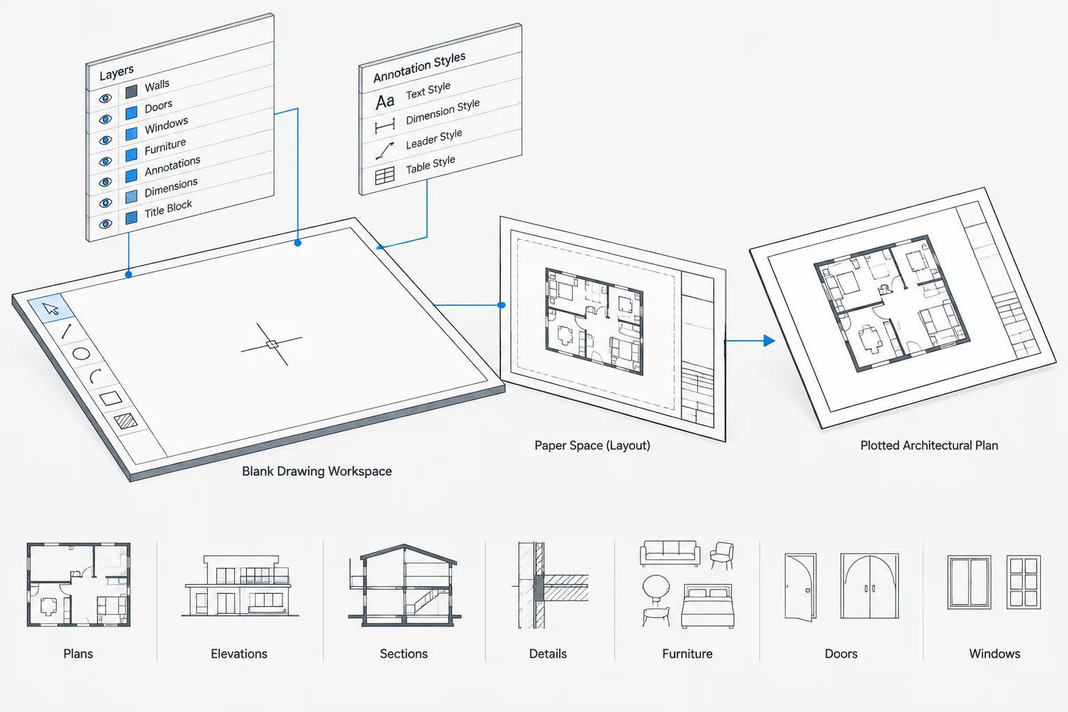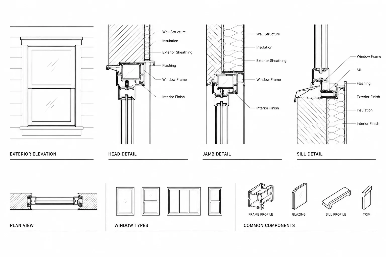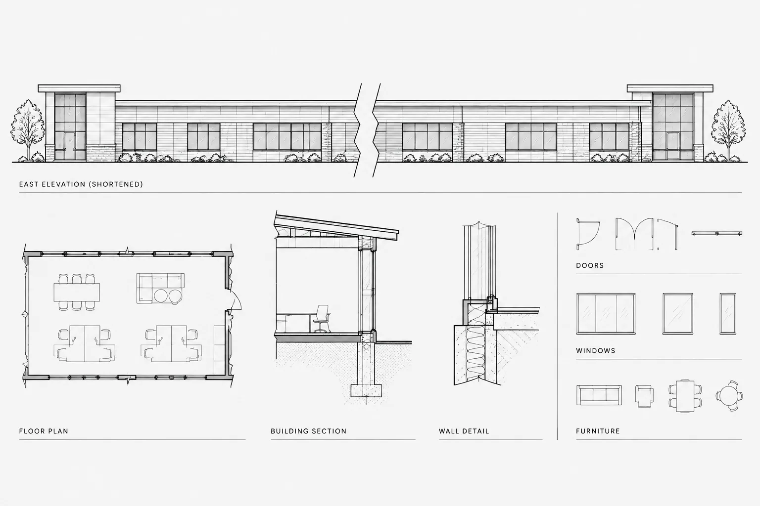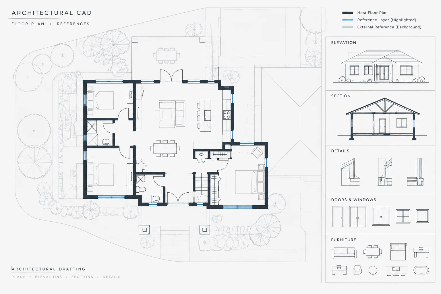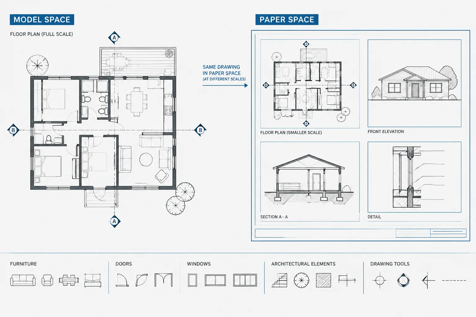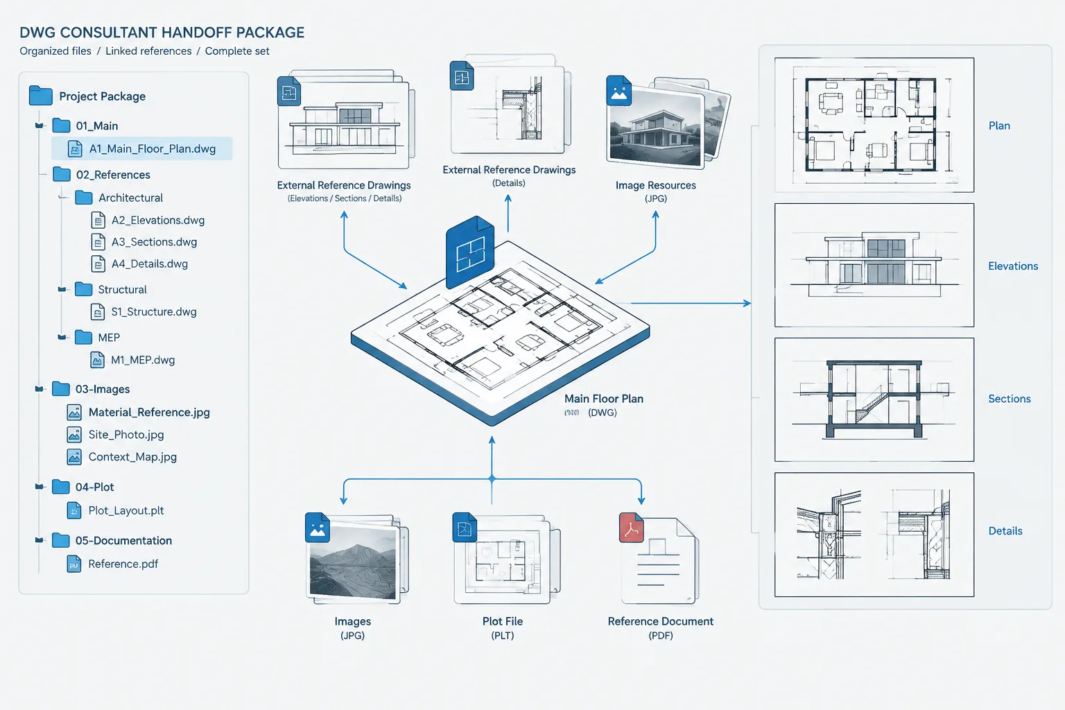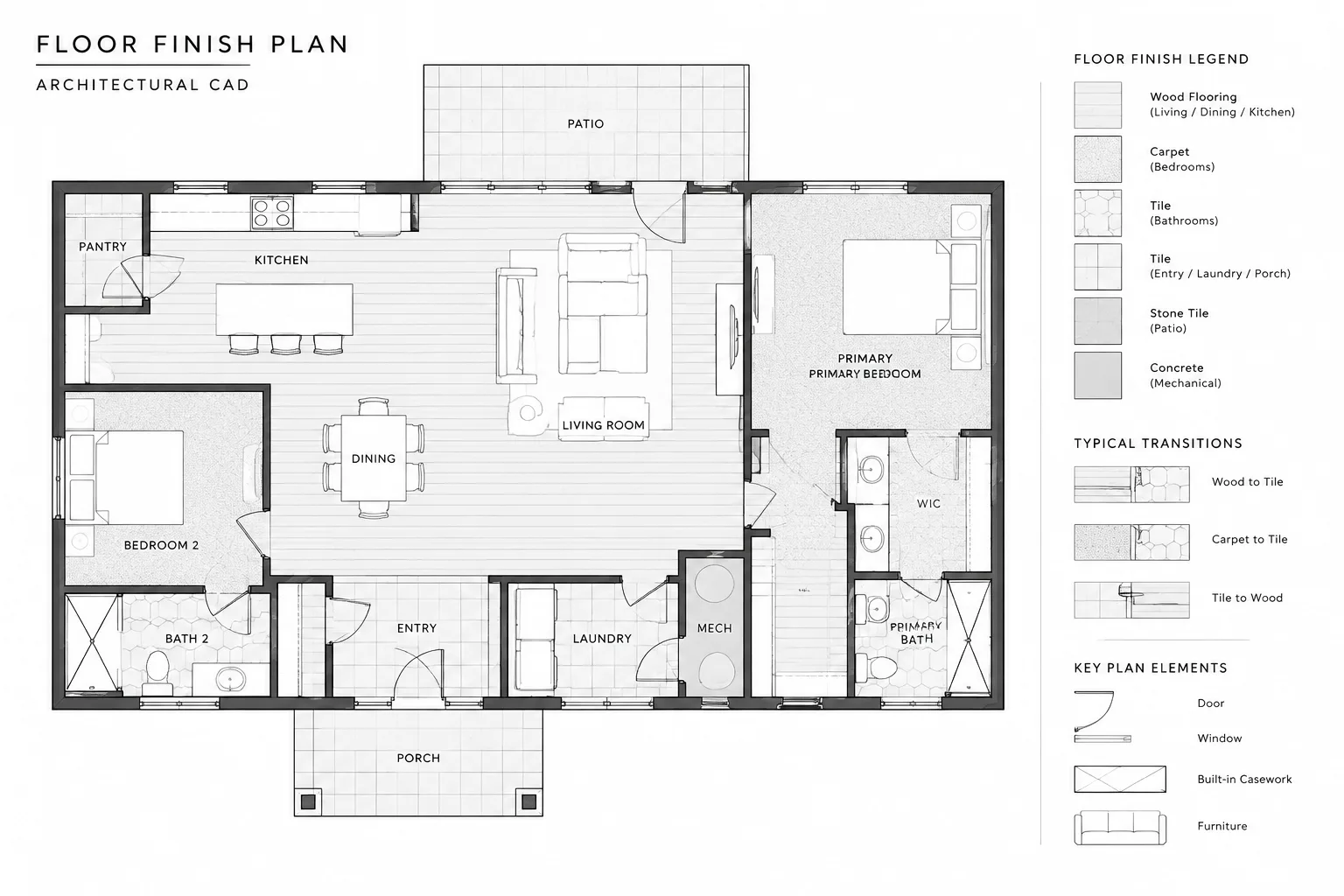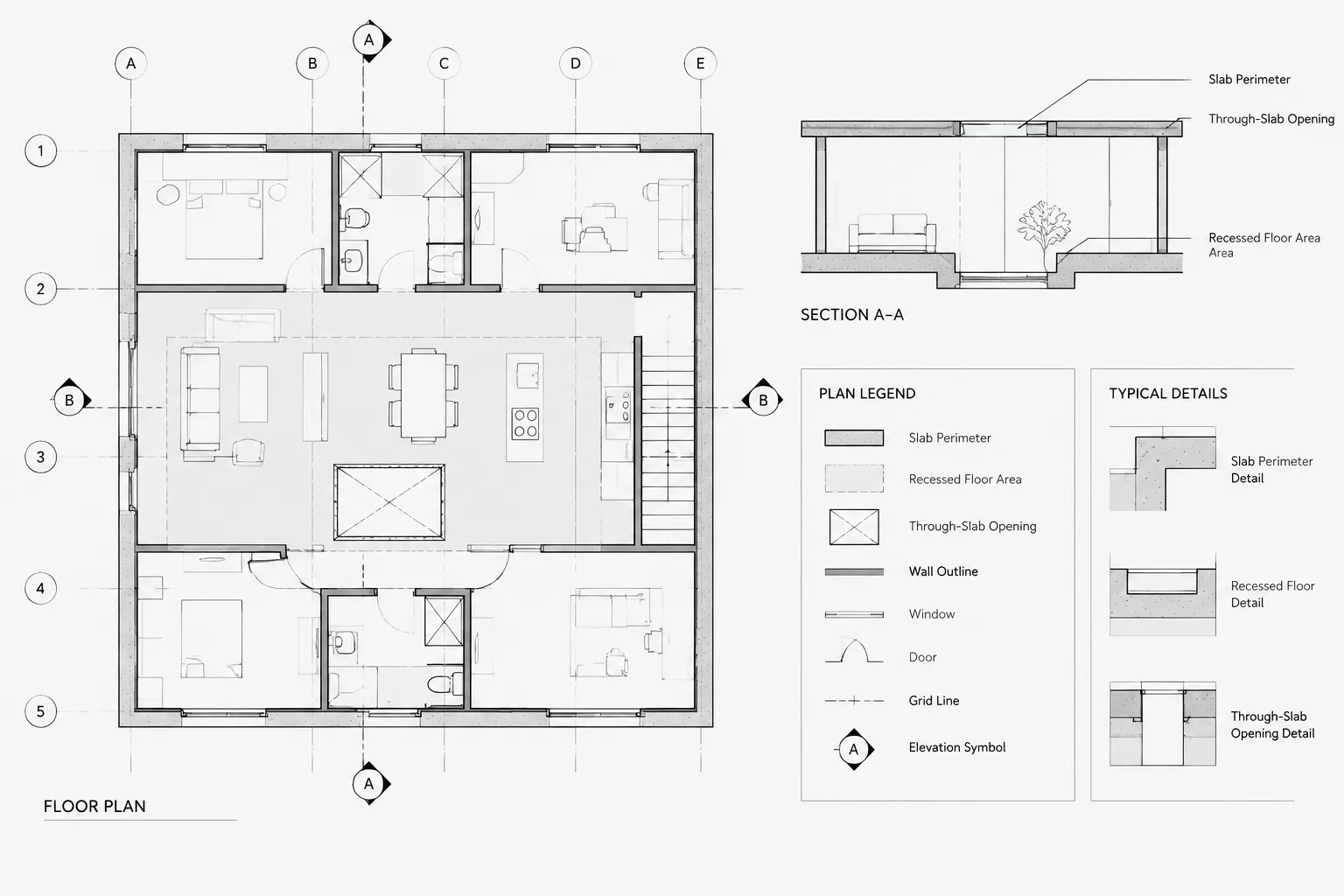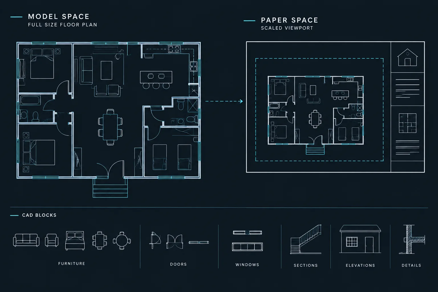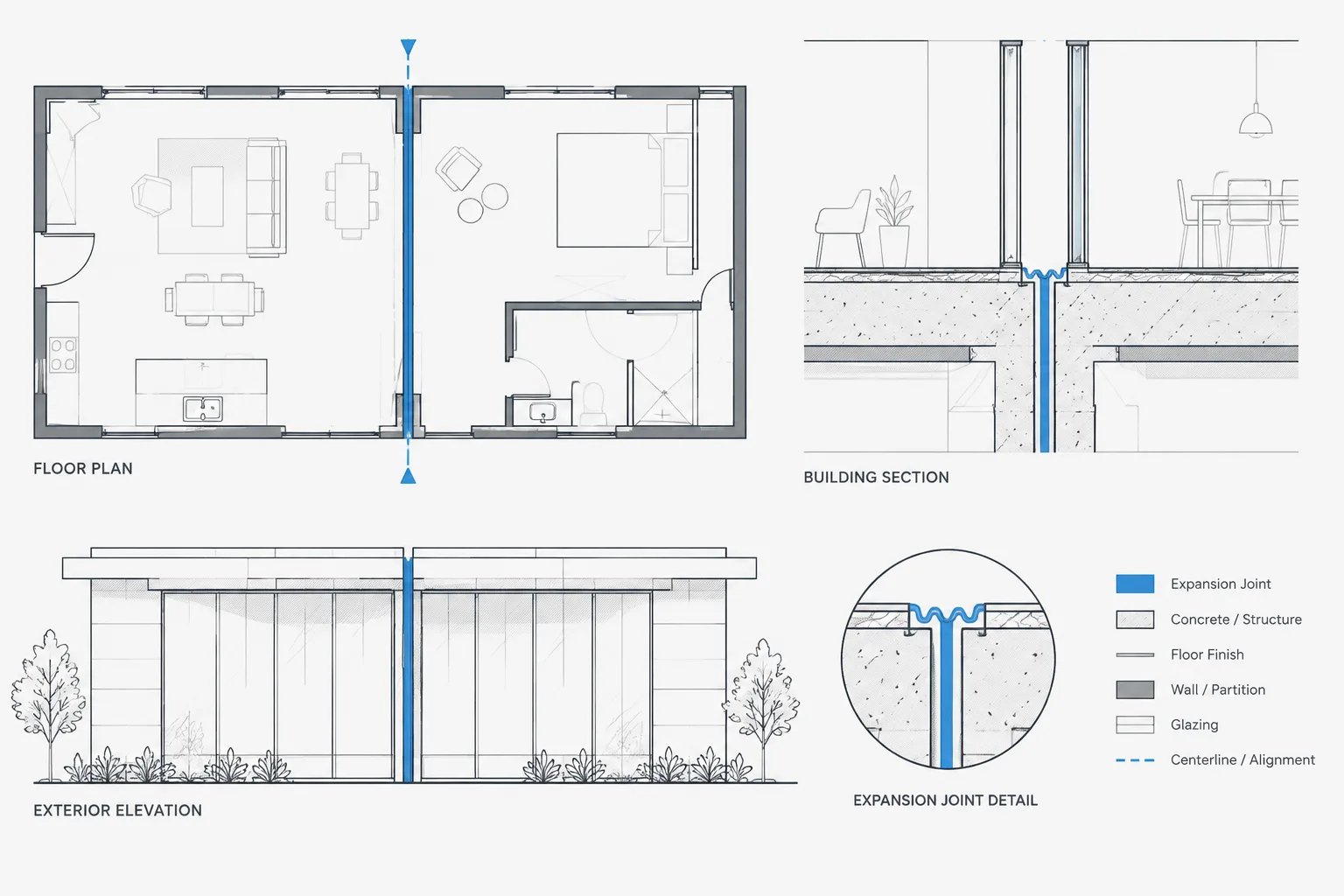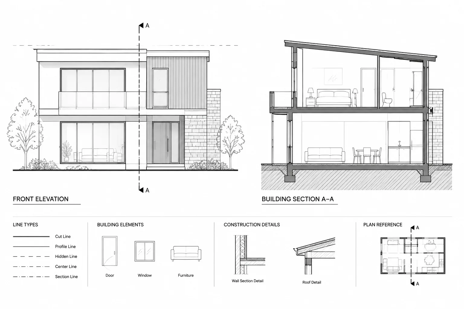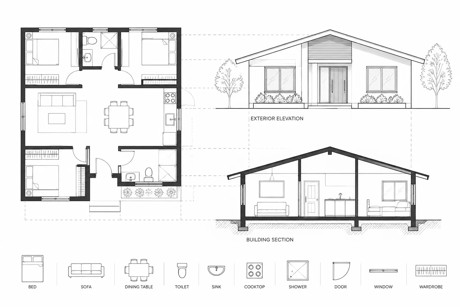
Coordinating plans, elevations, and sections in CAD is an information-management task as much as a drafting task. Each view must communicate its own purpose while remaining consistent with the geometry, levels, openings, and references shown elsewhere in the drawing set.
This guide explains how to establish controlling references, project geometry between views, manage external references and construction layers, and review revisions without treating any drawing as an isolated image. The workflow applies most directly to conventional DWG production, where coordination depends on clear drafting responsibilities and deliberate cross-view checks.
Architectural plans, elevations, and sections describe the same building from different directions. When these views are drafted independently, however, walls shift, openings move, floor levels disagree, and roof profiles become difficult to verify. A coordinated CAD workflow treats each drawing as a related representation of shared building geometry rather than as an isolated illustration.
The goal is not to make every view update automatically. In a conventional DWG workflow, the priority is to establish dependable reference geometry, identify which view controls each type of information, and make revisions in a deliberate sequence. This approach improves drawing accuracy while keeping files understandable for other drafters, consultants, and reviewers.
Why Views Become Uncoordinated
Most discrepancies are caused by workflow problems rather than difficult geometry. Common causes include:
- Drafting an elevation from a printed plan instead of the current plan DWG.
- Moving doors or windows in plan without reviewing related elevations and sections.
- Using different floor, ceiling, parapet, or roof references in separate files.
- Tracing visible geometry without preserving projection relationships.
- Copying an old view into a new project and leaving obsolete linework behind.
- Exploding or binding references too early, creating disconnected duplicate geometry.
- Allowing presentation adjustments to be mistaken for actual building changes.
A drawing may look convincing by itself while still contradicting the rest of the set. Coordination therefore requires comparisons between views, not merely cleanup within each view.
Define the Source of Truth for Each Type of Information
Before drafting, decide which drawing or project record controls each major category of geometry. There does not need to be one universal source for everything. A practical hierarchy might assign wall locations and room boundaries to the floor plan, vertical levels to a section or level diagram, and exterior material composition to the elevations and details.
| Information | Typical controlling reference | Views that should be checked |
|---|---|---|
| Wall and column location | Coordinated floor plan or structural background | Plans, sections, elevations, enlarged views |
| Door and window position | Floor plan with opening data | Elevations, sections, schedules |
| Floor and roof levels | Approved project datum and coordinated sections | Elevations, sections, stairs, exterior details |
| Ceiling relationships | Reflected ceiling plan and coordinated sections | Interior elevations, partitions, soffit details |
| Exterior profile | Roof plan, plans, and building sections together | Exterior elevations and envelope details |
| Material boundaries | Design elevations and assembly details | Elevations, sections, schedules, keynotes |
The controlling reference should reflect the project team’s agreed workflow. It must not be assumed that a plan automatically controls vertical information or that an elevation controls construction depth.
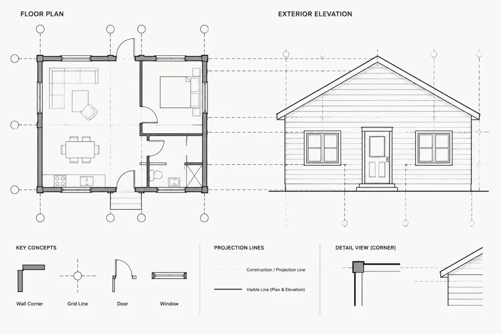
Establish Shared Datums and Reference Lines
Reliable coordination begins with stable references. Horizontal control commonly includes grids, principal wall faces, structural centerlines, and major opening locations. Vertical control includes floor levels, landings, ceilings, roof edges, parapets, and other project datums.
Place working projection lines on dedicated non-plotting layers or clearly identified construction layers. These lines should be easy to display during coordination and easy to hide before plotting. Avoid mixing them with visible building linework, because temporary guides can otherwise appear in issued sheets or be deleted accidentally.
Use consistent coordinate origins when related DWG files are referenced together. If files cannot share an origin, document the insertion method and avoid casual repositioning. A reference that has been nudged by eye may appear aligned at one location while being incorrect elsewhere.
A Practical Plan-to-Elevation Workflow
1. Reference the current plan
Attach the relevant plan as an external reference when the file structure permits. An xref preserves a connection to the source drawing and makes later plan changes visible. Control unnecessary plan layers through layer visibility rather than editing the referenced geometry.
2. Project major horizontal locations
Project wall faces, corners, grids, openings, columns, and significant changes in depth from the plan toward the elevation. Construction lines or temporary vertical lines are useful because they reveal relationships without becoming finished elevation graphics.
3. Add vertical control
Establish floor lines and other approved vertical datums from coordinated project information. Do not estimate heights from visual proportions or from an unverified background. The elevation should be built at the intersection of projected plan locations and confirmed vertical levels.
4. Draw visible depth deliberately
An elevation is not a flattened plan edge. Determine which surfaces are closest to the viewer, which elements are recessed, and where wall returns or projecting components occur. Apply lineweight hierarchy after the geometry is understood so that profile lines, primary edges, joints, and surface patterns communicate depth clearly.
5. Compare openings and identifiers
Confirm that each visible door and window aligns with the plan location and corresponds to the intended tag or schedule entry. Check grouped openings, corner conditions, and openings near changes in wall plane carefully. A schedule can be internally consistent while the elevation still shows the wrong arrangement.
A Practical Plan-to-Section Workflow
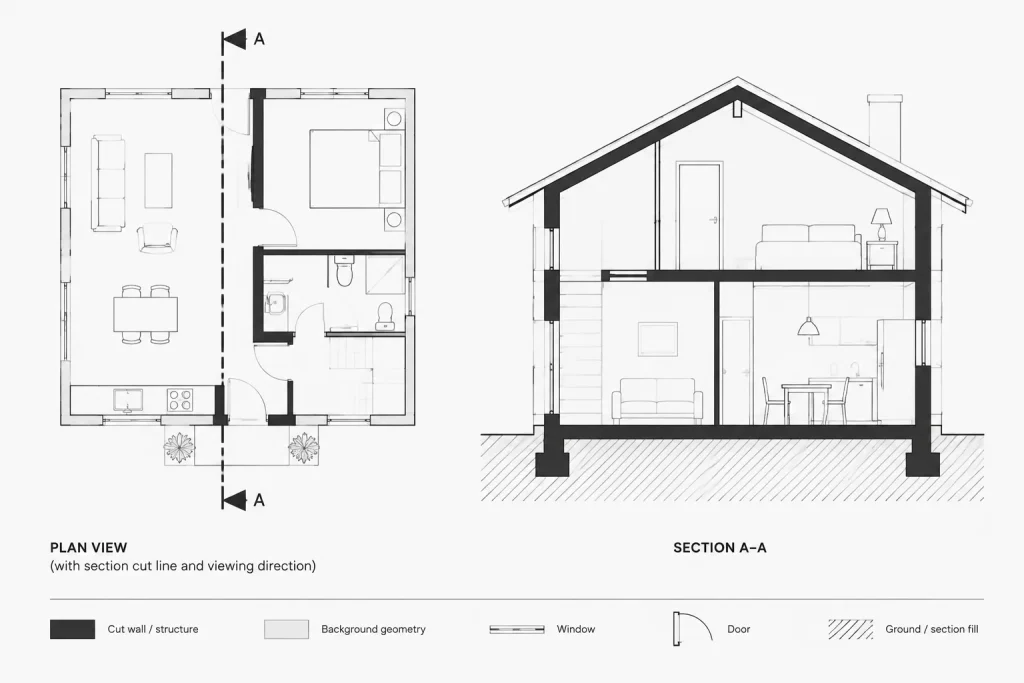
A section requires more interpretation because it distinguishes cut construction from elements seen beyond. Start by confirming the section line, viewing direction, and extents in plan. Then reference the plan and project the geometry intersected by the cut.
- Identify exactly where the cut passes through walls, openings, stairs, roofs, and floor assemblies.
- Draw cut elements separately from background elements so their graphic hierarchy can be controlled.
- Project nearby geometry only when it helps explain the space or construction.
- Coordinate floor, ceiling, roof, and grade relationships against approved vertical references.
- Check that the section callout in plan points to the correct drawing and viewing direction.
Do not move the effective cut location merely to make the section easier to draw unless the plan callout is also revised. If a section intentionally combines information from offset locations, represent and label that drafting convention clearly according to the project method.
Keep Projection Geometry Separate from Published Linework
Projection lines are coordination tools, not finished building objects. A useful layer structure separates temporary projection geometry, referenced backgrounds, cut linework, visible linework, overhead or concealed elements, annotation, and poche or material patterns.
This separation supports several tasks: projection guides can be frozen in sheet viewports, backgrounds can be halftoned, cut objects can receive stronger plotted emphasis, and annotation can be reviewed without visual interference. It also prevents a future editor from mistaking a construction line for an actual wall or edge.
Coordinate Revisions in a Predictable Sequence
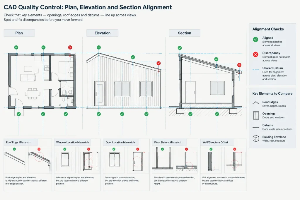
When the design changes, revise the controlling geometry first. Then update dependent views in a consistent order. For example, a moved opening may require a plan revision followed by checks of the exterior elevation, interior elevation, wall section, detail references, tags, and schedules.
Do not rely only on the visible xref change. An updated background can expose a conflict without correcting locally drafted elevation or section linework. Use revision clouds or internal markup tools during the review period, but remove temporary coordination marks according to the project’s issue process.
Useful Cross-View Checks
Before a drawing issue, perform targeted comparisons rather than reviewing each sheet in isolation:
- Compare overall building extents in plan with the corresponding elevation widths.
- Check that grids and primary structural elements align across plans and sections.
- Trace each major opening through plan, elevation, section, tag, and schedule.
- Verify that floor and roof datums carry consistently through all vertical views.
- Compare roof-plan edges with elevation profiles and section slopes.
- Review stairs, ramps, shafts, and other multilevel elements in more than one view.
- Confirm that material changes occur at compatible locations in elevations and details.
- Check that section and elevation callouts point to current sheet references.
Avoid False Alignment
Objects can appear aligned on screen even when they are not geometrically related. Thick lineweights, hatch boundaries, masking objects, and low zoom levels can conceal small discrepancies. Compare object snaps, coordinates, or projected construction lines rather than relying on visual judgment alone.
Also distinguish intentional graphic offsets from dimensional geometry. Tags, break lines, material symbols, and slightly separated coincident lines may be adjusted for readability. Those presentation choices should not be used as control points for other views.
Final Quality-Control Checklist
- Confirm that all referenced files are current and loaded from the intended locations.
- Verify shared origins, insertion points, and rotation before projecting geometry.
- Check horizontal locations against the current plan.
- Check vertical positions against approved project datums.
- Review opening locations, identifiers, and schedule relationships.
- Separate cut, profile, background, and projection graphics by layer and lineweight purpose.
- Inspect roof, ceiling, floor, and grade relationships across multiple views.
- Remove or freeze non-plotting construction geometry in published viewports.
- Plot a test sheet to catch masked, hidden, or visually misleading discrepancies.
Good cross-view coordination is less about tracing and more about controlled information flow. Shared references, clearly assigned sources of truth, disciplined projection, and systematic revision checks allow plans, elevations, and sections to operate as one architectural drawing system.
Turn Coordination Checks Into a Repeatable Review Process
A strong workflow should make discrepancies easy to find, assign, and resolve. Instead of relying on a general instruction to “coordinate the drawings,” identify the affected building element, the controlling reference, and every dependent view that requires review.
For example, an opening revision is not complete when its plan symbol moves. The drafter should also determine whether the change affects an exterior elevation, interior elevation, section, detail, tag, schedule, dimension string, or annotation reference. Some related views may require no graphic change, but they should still be checked before the revision is considered closed.
Record the reason for geometry changes
When several people edit related DWG files, unexplained movement can lead to repeated corrections. A short internal note or markup should distinguish a design revision from a drafting correction, background update, or presentation adjustment. This helps the next reviewer decide whether dependent views must change.
Review relationships rather than isolated objects
Coordination becomes more reliable when the reviewer follows a building element through the drawing set. A wall can be traced from its plan location to its elevation profile and section assembly. An opening can be followed from its plan position to its head and sill relationships, tag, and schedule entry. A roof edge can be compared among the roof plan, exterior elevation, and building section.
Use plotted output as a separate check
Geometrically correct CAD linework can still communicate poorly after plotting. Layer states, masking, hatch patterns, viewport settings, and lineweight hierarchy may hide conflicts that are visible in the model environment. Review both the underlying geometry and the published sheet appearance before issue.
Handoff Questions for Shared CAD Work
- Which file or drawing currently controls the revised geometry?
- Which related views have been checked against that source?
- Are projection guides and backgrounds clearly separated from published linework?
- Has any referenced file been repositioned, rotated, replaced, or detached?
- Are unresolved differences documented for the next drafter or reviewer?
- Does the plotted sheet show the same relationships that were verified in the working file?
A clear handoff prevents later editors from rebuilding the same coordination logic. The result is not merely cleaner CAD; it is a drawing set in which revisions can be followed and verified across views.
Frequently Asked Questions
Should the floor plan always control the elevation and section?
No. The plan commonly controls horizontal locations, but vertical datums, assembly depths, roof relationships, and material transitions may be controlled by sections, elevations, details, or other coordinated project information. The project team should identify the controlling reference for each type of information.
Why use an xref instead of copying plan geometry into another DWG?
An external reference preserves a visible relationship to the source file and helps expose later changes. Copied geometry becomes independent and may remain unchanged after the source is revised. An xref still requires review because it does not automatically correct locally drafted elevation or section linework.
Can plans, elevations, and sections share the same CAD origin?
Related files benefit from a documented coordinate strategy, especially when backgrounds are referenced together. If a shared origin is not practical, the insertion and alignment method should be recorded and applied consistently rather than adjusted by eye.
How can a drafter tell whether an apparent misalignment is real?
Check object snaps, coordinates, projection lines, and controlling datums rather than relying only on screen appearance. Lineweights, hatches, masks, and low display magnification can make separate objects appear aligned.
What should be checked after moving a door or window?
Review every view and record connected to the opening, including relevant plans, elevations, sections, dimensions, tags, schedules, and details. The exact set of affected drawings depends on how the opening is documented.
Should projection lines appear on published sheets?
Projection geometry is generally a working coordination aid. Keep it on clearly identified construction or non-plotting layers so it can be displayed during drafting and hidden or frozen in published views.