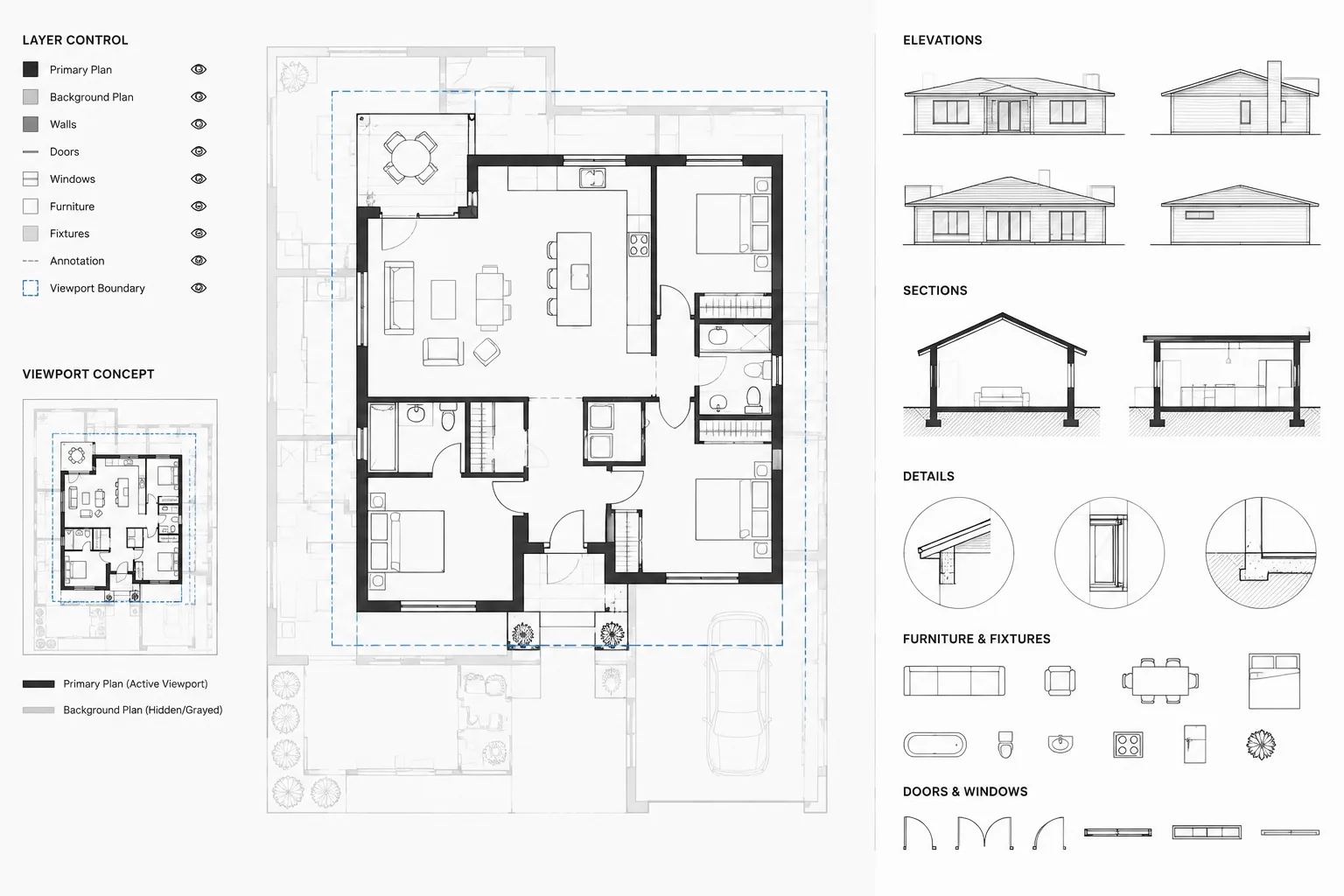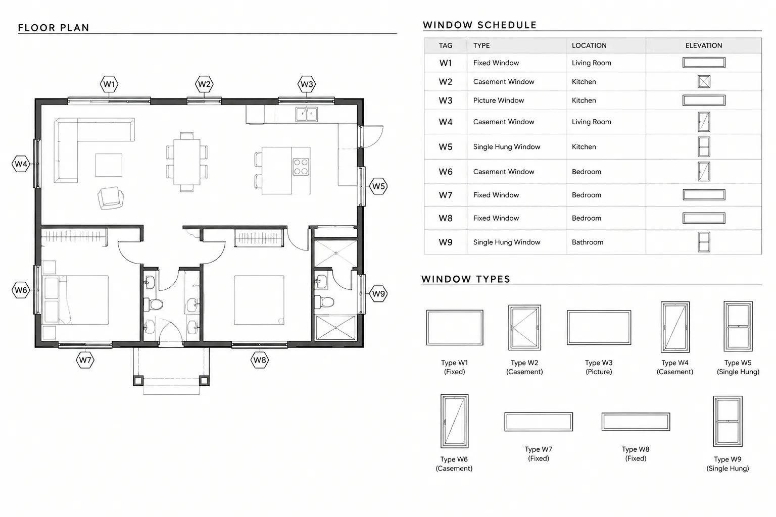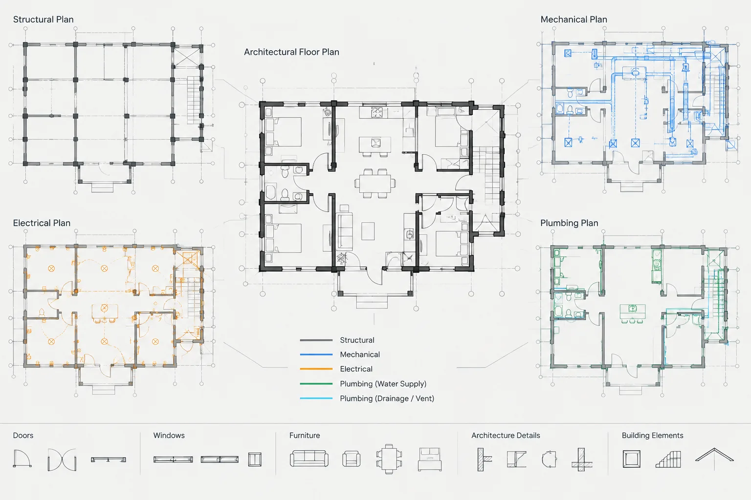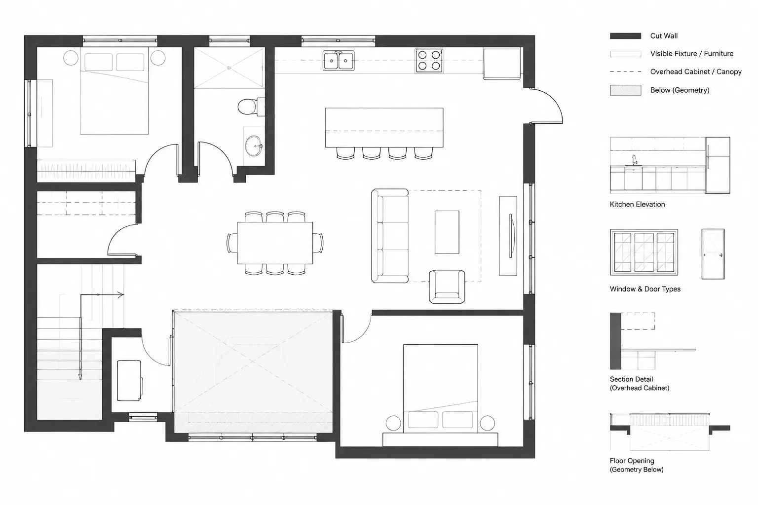
Showing vertical relationships in a two-dimensional plan requires more than choosing a dashed linetype. The drawing must distinguish what the plan cuts, what is visible at the current level, what occurs overhead, and what belongs below the floor.
This guide explains how to make those distinctions readable in CAD without crowding the plan. The emphasis is on graphic hierarchy, meaningful layer organization, selective representation, and coordination between related views.
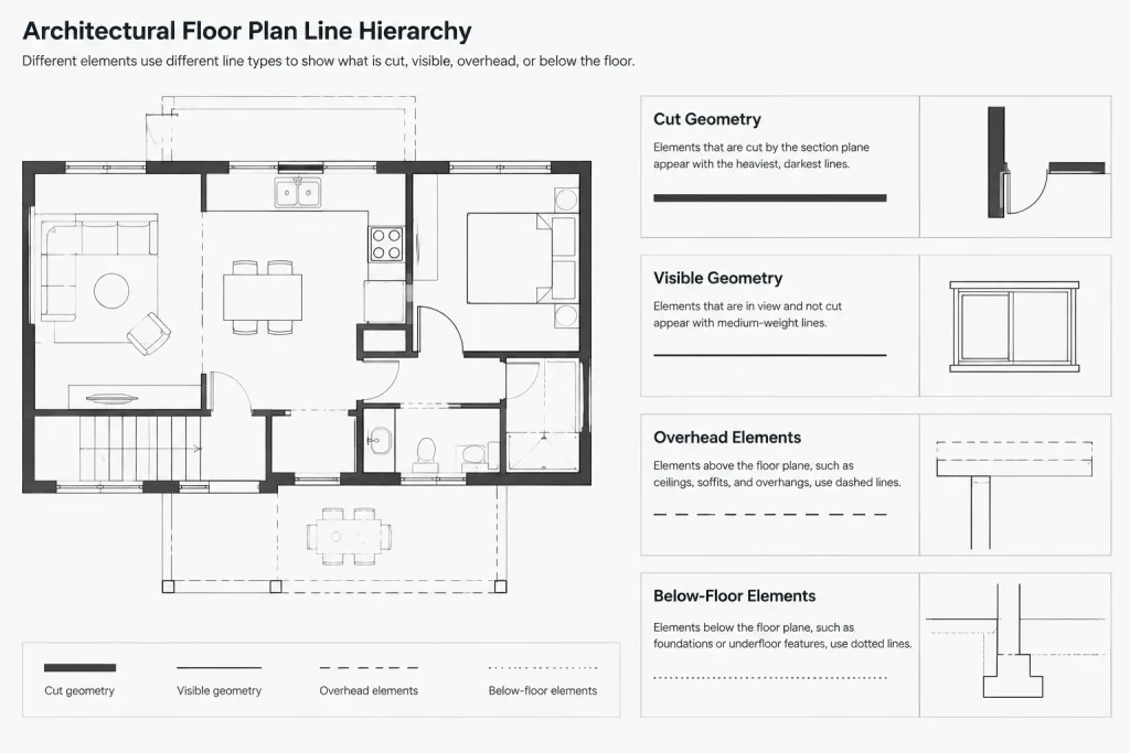
An architectural floor plan is not simply a view of everything at one elevation. It is a diagram assembled from cut elements, visible surfaces, overhead features, and selected information located below the primary floor level. The drafter must decide which elements help explain the building and how each category should appear.
When elements above and below in floor plans are shown without a consistent graphic system, drawings become difficult to read. Overhead cabinets may look like floor objects, steps may disappear, and projections from another level may be mistaken for walls. A reliable CAD workflow separates these conditions by meaning, applies a clear line hierarchy, and coordinates them with sections, elevations, reflected ceiling plans, and other views.
Understand the floor plan as a constructed view
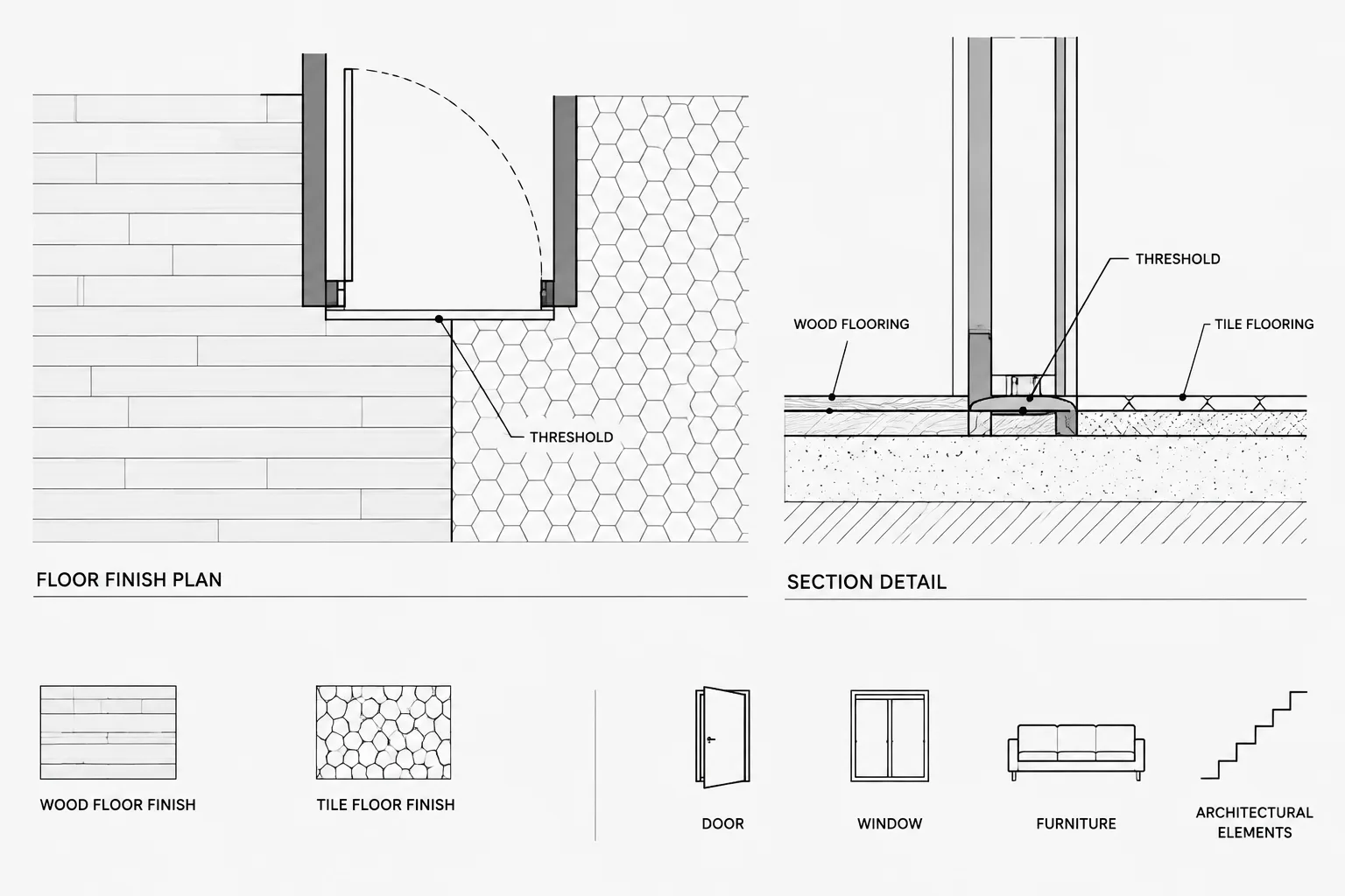
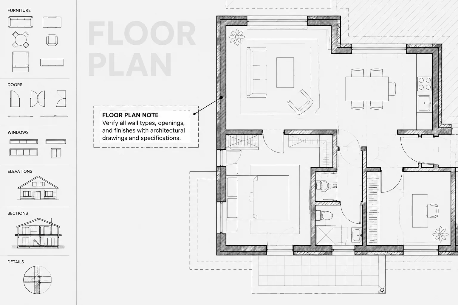
A floor plan is commonly understood as a horizontal section through a building, viewed downward. In practice, however, the final drawing often contains more than the geometry intersected by that conceptual cut.
Plan information can be organized into four broad categories:
- Cut elements: Walls, columns, door openings, and other components intersected by the conceptual plan cut.
- Visible elements below: Floors, fixtures, furniture, stairs, counters, and similar objects visible beneath the cut.
- Overhead elements: Features above the cut that are important to understanding the space, such as upper cabinets, beams, canopies, roof overhangs, or openings above.
- Below-floor elements: Selected features beneath the level being documented, such as lower stair runs, pits, recesses, or outlines of construction on a lower level.
These categories are conceptual rather than universal plotting rules. Their exact graphic treatment should follow the project drawing standard and remain consistent throughout the set.
Build a readable line hierarchy
Different locations should not be communicated by linetype alone. Lineweight, contrast, continuity, and surrounding context all contribute to the meaning of an object.
| Plan condition | Typical graphic role | Coordination concern |
|---|---|---|
| Cut by the plan | Strongest plan emphasis | Must agree with wall, opening, and structural locations |
| Visible below the cut | Clear but lighter than cut geometry | Should remain subordinate to major boundaries |
| Above the cut | Distinct overhead convention, often broken or differentiated | Must not be confused with hidden or demolished work |
| Below the floor or beyond the view | Limited, subdued reference information | Show only when it explains an opening, edge, or vertical relationship |
Cut walls and columns normally establish the visual structure of the plan. Visible fixtures and casework support that structure. Overhead and below-floor elements should generally recede so they do not compete with the plan cut.
A broken line is frequently used for overhead information, but a broken line can also represent hidden work, demolition, centerlines, property information, or other project-specific meanings. Do not assume that every dashed line will be understood. Coordinate the convention with the drawing legend, layer names, notes, and the rest of the sheet set.
Create layers based on meaning
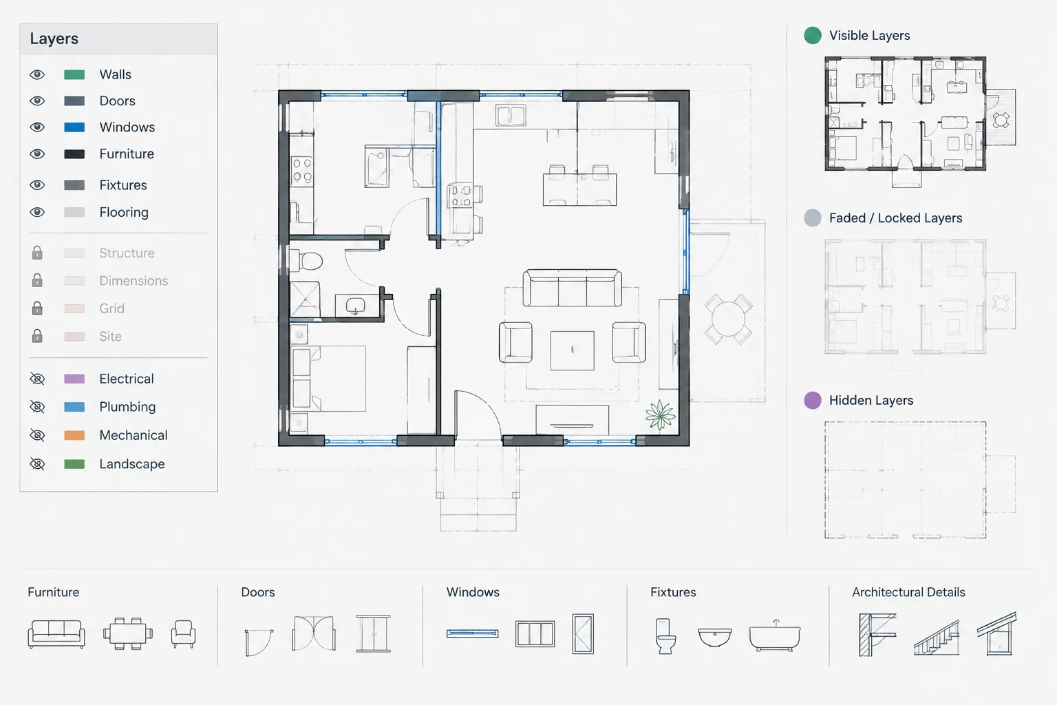
Placing all dashed objects on one generic layer makes later coordination difficult. Instead, organize layers around what the objects represent. An office may separate overhead architectural items, structural features above, casework above, floor openings, and elements below the current level.
A useful layer strategy should allow the team to:
- Identify why an object is shown with a different convention.
- Control visibility independently in different plan types.
- Apply consistent color, linetype, and plotted weight through layer properties.
- Temporarily isolate overhead or below-floor information for review.
- Avoid changing object properties individually when the graphic standard changes.
Keep routine geometry set to follow its layer properties unless a deliberate exception is required. Untracked object-level overrides can make two apparently identical overhead lines plot differently.
Draft overhead elements selectively
An element should not be shown overhead merely because it exists above the conceptual cut. Include it when it affects layout, clearance, access, orientation, or coordination.
Upper cabinets and shelving
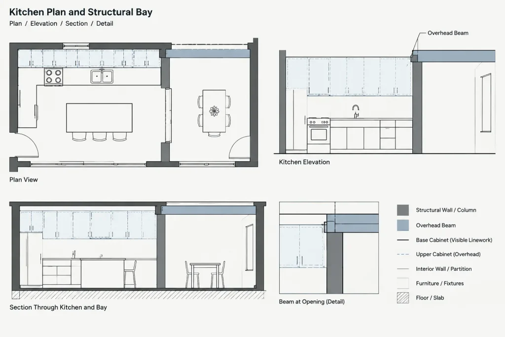
Upper cabinets may be useful in kitchens, workrooms, laboratories, storage areas, and similar spaces. Their plan outlines help coordinate counters, sinks, equipment, outlets, and vertical clearances. Keep upper cabinet graphics distinct from base cabinets so the plan does not imply that both occupy the floor.
Beams and structural projections
An overhead beam can affect ceiling layout, partition termination, door placement, or the perception of an opening. Show it when it is relevant to the architectural plan, but coordinate its location with the structural background. Avoid redrawing structural geometry from memory when a controlled reference is available.
Canopies, overhangs, and projections
Exterior projections may explain protected entrances, building limits, and relationships to paving or landscape elements. The projection outline should remain visually separate from the wall or roof edge that is actually cut or visible at the plan level.
Openings and features above
Double-height spaces, skylights, ceiling openings, and upper-level edges can require plan representation. Determine whether the information belongs on the floor plan, reflected ceiling plan, roof plan, or an enlarged view. Repeating all related geometry on every plan often creates conflicts instead of clarity.
Show below-floor information only when it adds meaning
Below-floor features should be more selective than visible plan geometry. Their main purpose is to explain vertical relationships that would otherwise be ambiguous.
Common examples include:
- A stair run continuing below the current level.
- The edge of a floor opening through which lower construction is visible.
- A pit, recess, or depression requiring coordination with adjacent work.
- A lower roof or terrace visible from an upper floor.
- Construction beneath an open walkway, bridge, or mezzanine.
Start with the boundary that controls the current level, such as the floor opening or slab edge. Add the lower geometry afterward and keep it subordinate. If a lower level becomes the most visually prominent part of the plan, the hierarchy is probably reversed.
Handle stairs as a special plan condition
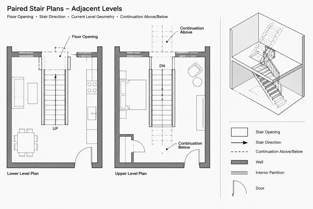
Stairs combine geometry below the cut, geometry intersecting the cut, and geometry continuing toward another level. This makes them a frequent source of inconsistent linework.
Establish the stair geometry from coordinated floor-to-floor information and use a deliberate break or transition to distinguish the portion represented in the current plan. Direction indicators and level references should agree with the destination shown elsewhere in the drawing set. Check the upper and lower plans together rather than editing each stair independently.
The goal is not to draw every tread visible in a three-dimensional model. The goal is to communicate direction, extent, openings, landings, and the relationship between levels without creating a dense patch of competing lines.
Coordinate plan types instead of copying graphics
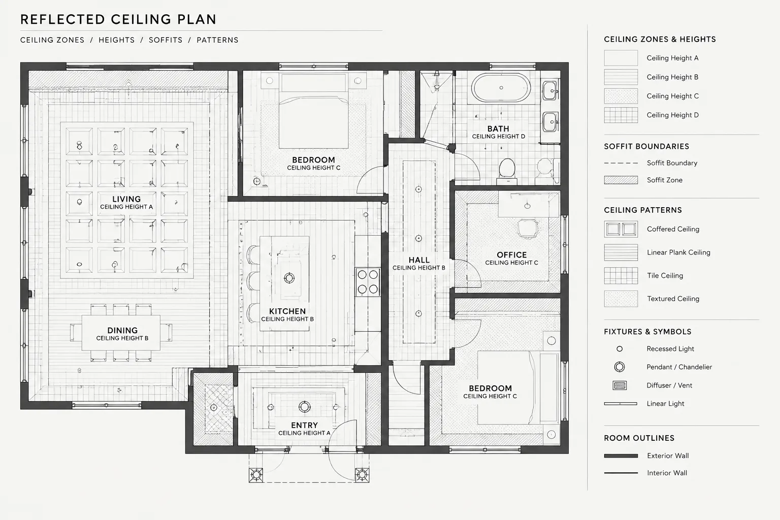
A floor plan, reflected ceiling plan, roof plan, and structural plan may describe related objects with different viewing logic. Copying linework between them without reconsidering its meaning can produce misleading results.
For each item, identify a primary source:
- Use the architectural floor plan for room boundaries, openings, and floor-level layout.
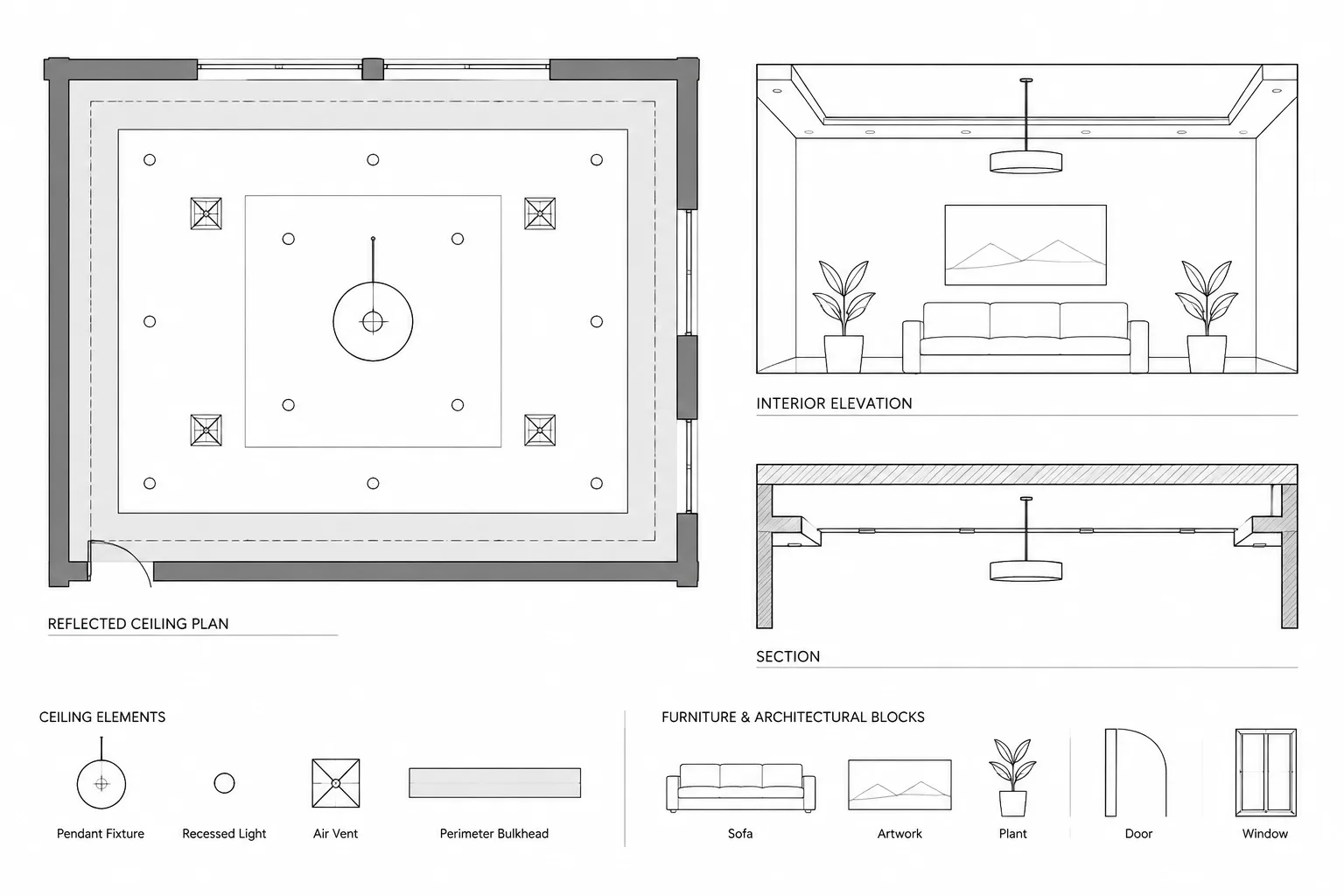
- Use the reflected ceiling plan for ceiling systems and overhead devices when that view communicates them more clearly.
- Use the roof plan for roof edges, drainage organization, and roof-mounted features.
- Use the structural background for beam, column, and framing coordination.
- Use sections and elevations to verify vertical relationships that cannot be confirmed in plan.
If an overhead feature appears in multiple views, establish which view controls its geometry and which views display it only for reference.
Use blocks carefully for overhead symbols
Blocks can standardize items such as upper cabinets, roof openings, access zones, or overhead equipment outlines. Before inserting a block, inspect its internal layers, linetypes, insertion point, rotation, and nested content.
A block should not force every component onto the same graphic layer. Where practical, separate the defining geometry from supplementary overhead or clearance graphics. Also confirm that mirrored blocks do not reverse readable text or directional symbols.
Perform a focused quality-control review
Review overhead and below-floor graphics separately from the general drawing review. Temporarily isolate the relevant layers and compare the plan with adjacent levels and referenced views.
- Confirm that every differentiated line has an understandable meaning.
- Check that overhead objects do not read as floor-mounted items.
- Verify that below-floor geometry does not overpower the current level.
- Compare stairs, shafts, atriums, and floor openings between adjacent plans.
- Check beams, canopies, and projections against their controlling references.
- Look for duplicate outlines created by copied blocks or overlapping references.
- Verify linetype appearance in the plotted sheet, not only in model space.
- Confirm that legends and general notes match the conventions actually used.
Finally, test the drawing without color. Many reviewers encounter plans as monochrome PDFs or printed sheets. If the meaning depends entirely on screen color, strengthen the hierarchy through lineweight, linetype, labeling, or selective simplification.
Keep the convention simple and project-specific
There is no benefit in showing every object above or below the plan cut. A successful floor plan presents enough vertical information to explain the design while preserving a clear reading of walls, openings, circulation, and room layout.
Define a limited set of graphic conventions, assign them to meaningful layers, and use sections or specialized plans for information that cannot be explained cleanly in the main floor plan. Consistency across levels and sheets is more valuable than adding more linework.
A practical decision process for plan visibility
Before adding an element from another elevation, identify what the line is expected to communicate. Its purpose should determine whether it appears on the floor plan and how strongly it is drawn.
- Locate the element: Decide whether it is cut, visible below the cut, overhead, or beneath the documented floor.
- Identify its purpose: Determine whether it explains an opening, circulation path, projection, clearance concern, or relationship between levels.
- Choose the controlling view: Confirm whether the floor plan, ceiling plan, roof plan, structural background, section, or elevation is the primary source.
- Assign a graphic role: Use layer, linetype, lineweight, and labeling together rather than relying on one property.
- Test for ambiguity: Check whether the line could be mistaken for a wall, hidden object, demolished work, centerline, or floor-mounted item.
- Remove unnecessary information: If the element does not improve spatial understanding or coordination, another view may communicate it more clearly.
Use an ambiguity audit before plotting
Review each differentiated outline and complete a simple statement: This line represents an element located… If its location and purpose cannot be explained quickly, the convention may need a note, a legend reference, a clearer layer assignment, or a different graphic treatment.
Compare the feature with adjacent floor plans and its controlling section or elevation. This is especially useful for stairs, floor openings, shafts, canopies, upper cabinets, beams, and projecting building elements. The final test is whether a reader can understand the current level first and the supplemental vertical information second.
Frequently asked questions
Should every overhead element be shown on a floor plan?
No. Show an overhead element when it contributes to layout, access, orientation, clearance coordination, or understanding of the building form. Information that primarily describes the ceiling or roof may be clearer in another plan type.
Should overhead lines always be dashed?
A broken linetype is common, but it is not universally reserved for overhead objects. The same visual pattern may have other meanings within a drawing set. Coordinate linetype with lineweight, layers, labels, legends, and office standards.
How should construction below a floor opening be represented?
Establish the current-level opening or slab edge first. Add only the lower geometry needed to explain the vertical relationship, and keep it visually subordinate to the boundaries of the documented level.
How can upper cabinets be distinguished from base cabinets?
Place upper cabinets on a meaning-based layer and apply the project convention for overhead objects. Their outline should remain readable without appearing to occupy the floor or competing with walls and base casework.
Why do overhead linetypes sometimes look inconsistent when plotted?
Possible causes include object-level overrides, block contents on unexpected layers, overlapping linework, and plotting behavior that differs from the model-space display. Inspect the objects, block definitions, layer properties, and plotted output together.
Which drawing should control an element shown in several views?
Assign a primary source based on what the element represents. Related plans can display it for reference, but its location should be checked against the view or discipline responsible for controlling that geometry.