Building envelope CAD details are most useful when they explain how assemblies connect rather than showing isolated collections of materials. A continuity-first approach follows each project-relevant control function through walls, roofs, openings, foundations, penetrations, and changes in construction.
The workflow below focuses on drawing organization, transition review, graphic clarity, and coordination. It should be applied alongside verified project requirements, consultant information, specifications, and manufacturer documentation.
Building envelope details become difficult to coordinate when they are treated as isolated construction fragments. A parapet detail may look complete by itself, yet fail to explain how a wall membrane connects to the roof assembly. A window jamb may contain every visible component but leave the perimeter transition unclear. The most reliable drafting approach is to follow each control layer continuously through the building rather than merely drawing a collection of materials.
This continuity-first workflow helps architects and CAD drafters organize building envelope CAD details around performance intent. It does not replace project specifications, engineering, manufacturer instructions, or specialist review. Instead, it provides a drawing method for identifying transitions, exposing gaps, and making details easier to coordinate.
What Is a Building Envelope Control Layer?
A control layer is a part of an exterior assembly intended to manage a particular environmental condition. Depending on the project and assembly, the design team may need to coordinate layers related to rainwater, air movement, heat flow, water vapor, drainage, or other project-specific requirements.
These functions are not always performed by separate products. One material may serve more than one role, while another role may depend on several connected components. For that reason, CAD drawings should not assume that every control function corresponds to a single line, sheet product, or hatch.
The project team must determine the actual materials, sequence, attachment, compatibility, and performance requirements. The drafter’s task is to represent that verified design consistently across plans, sections, elevations, and details.
Start with an Envelope Continuity Diagram
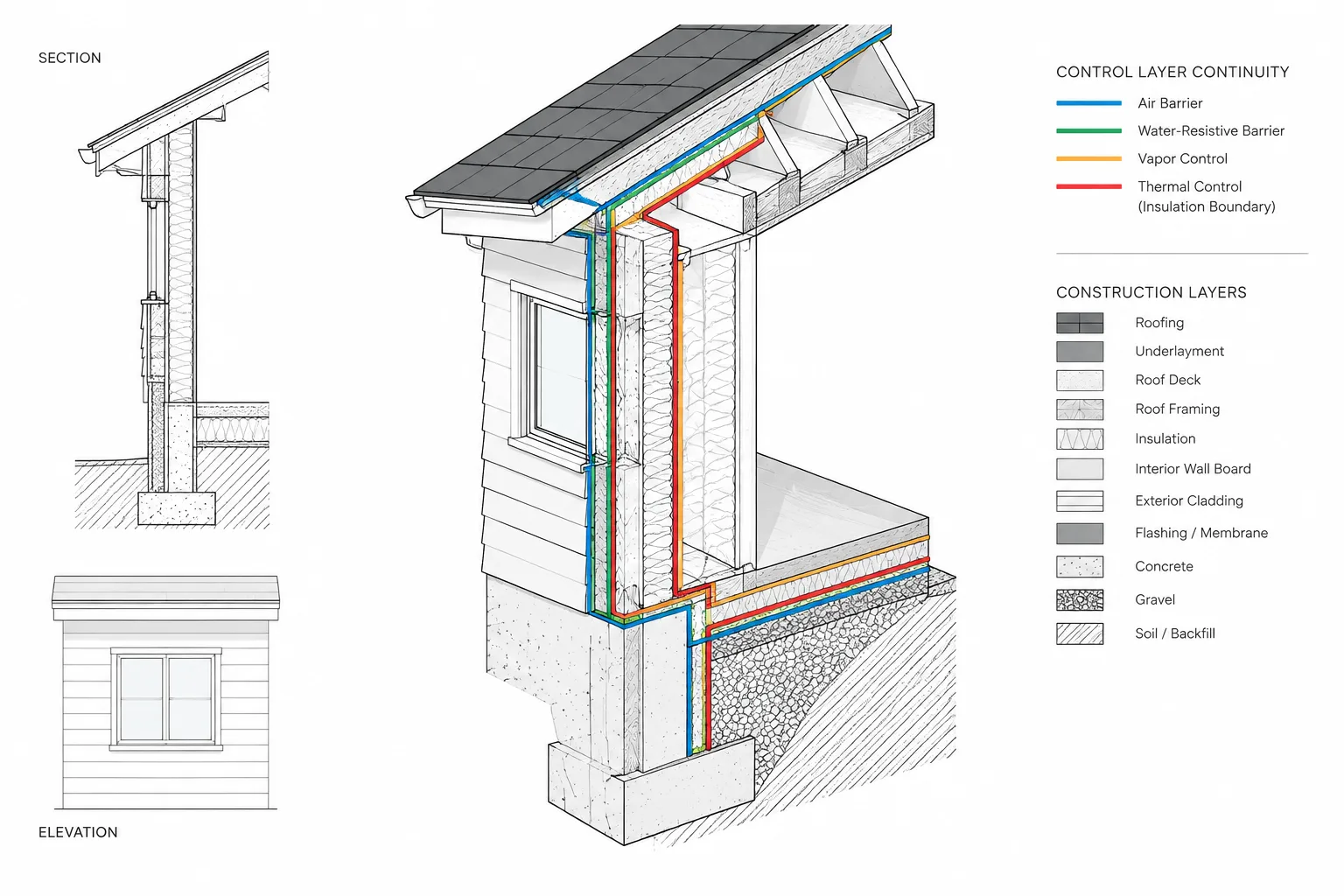
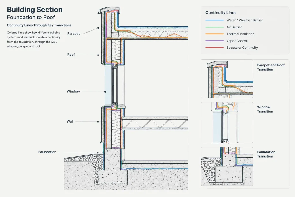
Before developing enlarged details, create a simplified building section showing the complete enclosure from foundation to roof. Use diagrammatic colored lines or distinct CAD layers to trace the primary control functions through the section.
This diagram is a coordination tool rather than a construction detail. Keep it simple enough that discontinuities are immediately visible. Trace each relevant layer around major conditions such as:
- Below-grade walls and foundation transitions
- Ground-floor slab edges
- Exterior wall bases and tops
- Windows, doors, and louvers
- Intermediate floor edges
- Balconies, canopies, and projections
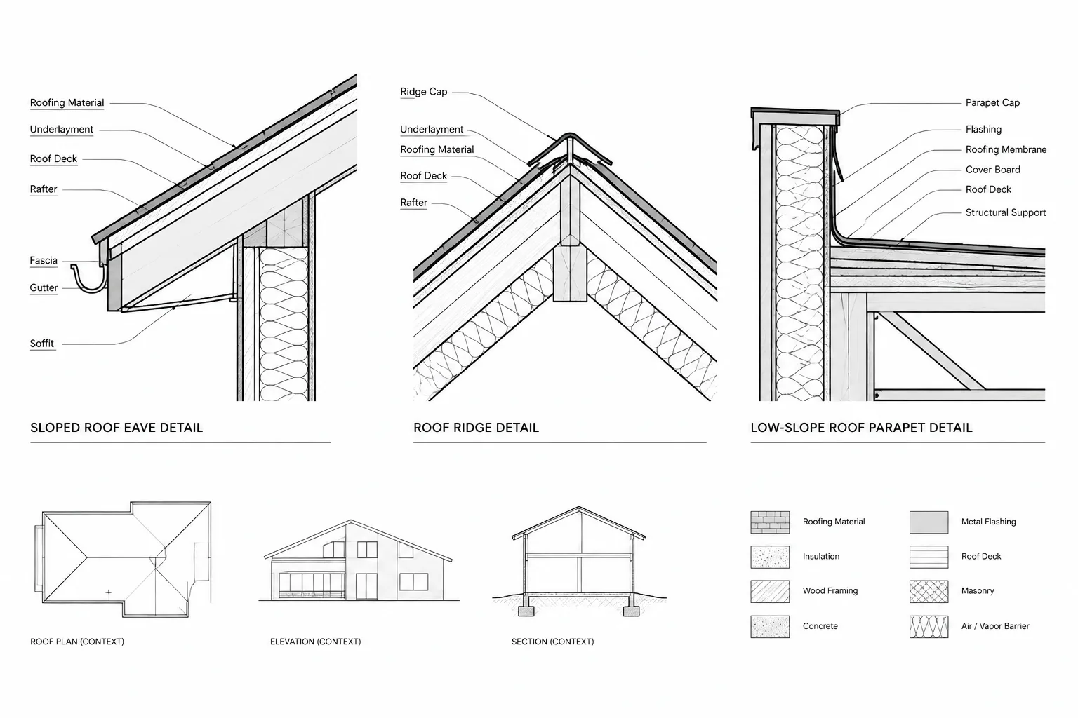
- Roof edges, parapets, and eaves
- Changes between cladding or wall systems
If a line cannot be followed through one of these conditions, the drawing set may need another detail, a revised assembly, or clarification from the responsible designer or consultant.
Organize the CAD File by Function and Material
Envelope details need enough graphic separation to remain understandable when plotted. Material outlines, cut elements, membranes, insulation, fasteners, sealants, annotations, and overhead geometry should not collapse into one visual layer.
A useful layer structure separates drawing information by purpose. The exact names should follow the project’s CAD standard, but the organization may distinguish among:
- Primary cut geometry
- Secondary visible geometry
- Membranes and thin control components
- Insulation and material hatches
- Sealants and joint components
- Flashings and sheet components
- Fasteners, anchors, and supports
- Diagrammatic continuity overlays
- Text, leaders, dimensions, and reference symbols
Do not rely only on color to communicate meaning. Colors may change during plotting, exporting, or consultant exchange. Combine layer organization with lineweight, linetype, hatch, labels, and clear geometry.
Build Details Around Transitions
Long, uninterrupted wall or roof areas are usually easier to understand than transitions. Drafting effort should therefore concentrate on places where assemblies change direction, meet another system, or are penetrated.
| Transition | Questions to Resolve in the Detail |
|---|---|
| Wall to foundation | Where does each layer begin or terminate, and how does the above-grade assembly connect to the below-grade condition? |
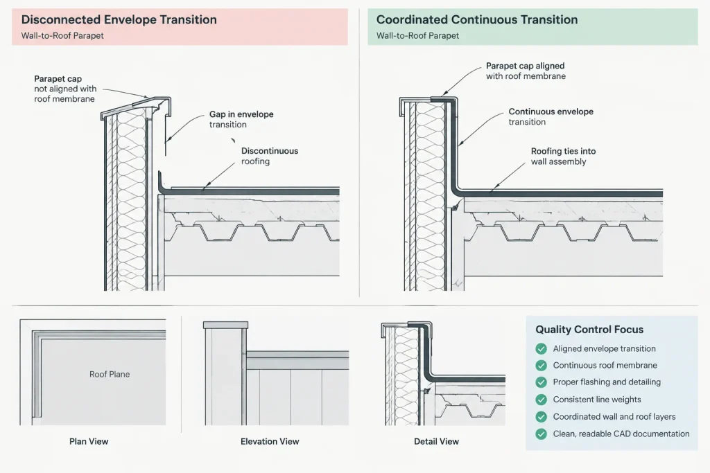
| Wall to roof | How do wall and roof control layers turn, overlap, connect, or terminate at the edge condition? |
| Window or door perimeter | How do the opening frame, rough opening, flashing, sealant, and surrounding wall assembly relate? |
| Cladding change | How are drainage, support, movement, and control-layer continuity addressed behind the visible finish transition? |
| Balcony or canopy connection | Which components pass through the enclosure, and how are the affected layers coordinated around them? |
| Penetration | Who provides the opening, sleeve, flashing, seal, support, and final closure? |
This approach prevents the visible finish from dominating the detail. Cladding joints and trim are important, but the concealed transitions behind them often require the most coordination.
Draft from Large Assembly to Small Component
Begin each detail with the major construction zones: structure, exterior wall assembly, roof or floor assembly, opening, and finish. Confirm their relative positions before adding thin membranes, clips, sealants, and fasteners.
A practical sequence is:
- Reference the coordinated plan or section geometry.
- Draw the principal structural and substrate boundaries.
- Add insulation and other continuous assembly zones.
- Trace the relevant control layers through the transition.
- Add cladding, roofing, flashings, trims, and closures.
- Show supports, attachments, joints, and penetrations only to the level appropriate for the drawing.
- Add notes, dimensions, and cross-references after the geometry is stable.
Working in this order reduces the temptation to force important layers around decorative or secondary geometry added too early.
Use Clear Graphics for Thin Components
Many envelope components are too thin to depict at their literal plotted thickness. A membrane drawn at exact physical thickness may disappear, while an oversized line may be mistaken for a gap or separate material.
Use a consistent office convention for diagrammatically enlarged thin components. Identify them with labels where their meaning is not obvious. Avoid stacking several identical heavy lines together, because the result can obscure the order of layers and the intended connection.
At crowded transitions, consider an enlarged detail rather than adding more lines to a small-scale section. The parent section should establish location and assembly relationships; the enlarged detail should explain the connection.
Coordinate Openings as Perimeter Conditions
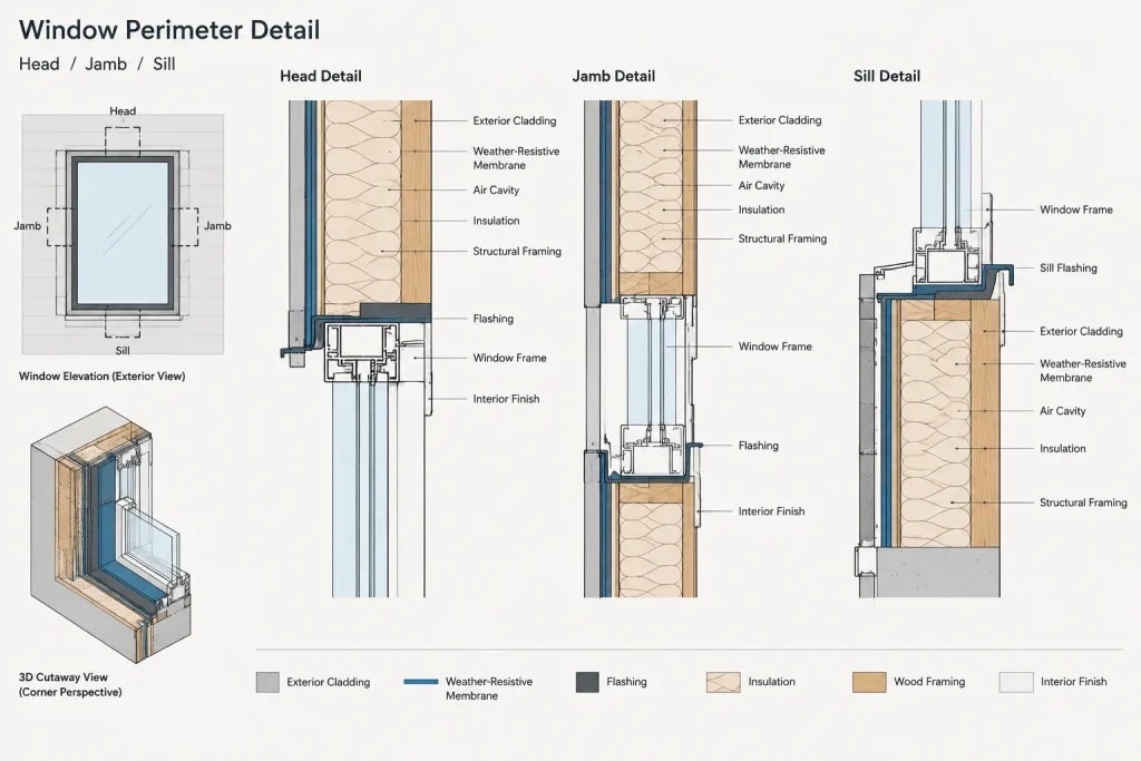
Windows, doors, louvers, and access panels should be reviewed around their full perimeter. A sill detail alone does not establish what occurs at the jamb or head, and conditions may differ where an opening meets another material or structural element.
Use related head, jamb, and sill details where necessary, and coordinate them against the same opening type and wall assembly. Check that frame position, wall depth, finish returns, perimeter joints, and control-layer transitions agree among plan, section, elevation, schedule, and detail references.
Generic product profiles should not be presented as verified project configurations. When product information is unavailable, clearly distinguish design intent from components that require later confirmation.
Control Repetition Without Hiding Differences
Typical details are useful only when their limits are clear. A standard window jamb may not apply at a corner, a cladding transition, a structural column, or a change in wall type.
Before reusing a detail, compare:
- Wall and roof assembly types
- Interior and exterior finish conditions
- Structure and substrate locations
- Opening or penetration type
- Exposure and drainage configuration
- Adjacent joints or movement conditions
- Consultant and manufacturer requirements
If the geometry is similar but the assembly differs, create a controlled variation rather than overwriting a shared detail with conflicting notes.
Keep Notes Specific and Coordinated
Notes should identify materials and actions clearly enough to support the drawing without attempting to reproduce the entire specification. Avoid vague phrases such as “seal as required” when the location, interface, or responsible trade is unclear.
Likewise, avoid placing unsupported performance claims in a detail. Required products, preparation, laps, terminations, fastening, testing, and compatibility must come from verified project information. If a decision is unresolved, track it as a coordination item instead of disguising it with a generic note.
Review Details with a Trace Test
A focused quality-control review can be performed by temporarily isolating or highlighting one control function at a time. Starting at the foundation, trace it through walls, openings, roof transitions, and penetrations.
During the review, ask:
- Can the layer be followed continuously through every referenced detail?
- Do adjacent details show the same sequence and terminology?
- Are terminations and transitions visibly resolved?
- Does a note contradict the drawn geometry?
- Are concealed components distinguishable from finish lines?
- Are detail references pointing to the correct assembly variation?
- Has information requiring specialist or manufacturer confirmation been identified?
Repeat the trace for each project-relevant function. This method is often more effective than reviewing details individually because it tests the enclosure as a connected system.
Maintain a Detail Transition Matrix
For projects with several wall, roof, and opening types, maintain a simple matrix listing major transitions and their associated detail references. Rows can represent assembly combinations, while columns identify bases, tops, openings, corners, penetrations, and material changes.
The matrix helps reveal missing conditions and reduces duplicate drafting. It also provides a practical way to track which details are typical, which are project-specific, and which still require input from another discipline.
Final Drawing Check
Before issuing envelope details, compare them with the current plans, elevations, wall sections, schedules, and consultant backgrounds. Confirm that detail titles, assembly names, references, and revision status agree throughout the set. Plot the sheets at their intended output size and inspect dense transitions for merged lines or unreadable notes.
Well-coordinated building envelope CAD details do more than show materials. They communicate how assemblies connect. By tracing control layers through transitions, separating graphic functions, and documenting unresolved interfaces, the drawing team can produce details that are clearer to review and more useful for project coordination.
Turning the Workflow into a Repeatable CAD Process
A continuity review works best when it is treated as part of drawing development rather than a final graphic cleanup. Establish the control-layer diagram early, connect it to the wall sections and enlarged details, and revisit it whenever an assembly, opening, projection, or structural interface changes.
Separate Design Intent from Product Resolution
The drawings should communicate the intended path through each transition without implying that an unverified product configuration has been approved. When a component depends on manufacturer information, consultant design, compatibility review, or field coordination, identify that dependency clearly and track it outside the detail as an unresolved item.
Use References to Connect Drawing Scales
The overall section should locate the enclosure systems, the wall section should establish assembly relationships, and the enlarged detail should clarify the transition. Cross-references should lead the reader through those views without forcing every component into the least detailed drawing.
Review Changes by Interface
When a wall type, roof edge, opening, or attachment changes, review the interfaces affected by that revision. Updating only the visibly changed component can leave outdated membranes, flashings, supports, notes, or detail references elsewhere in the set.
- Compare the revised condition with the continuity diagram.
- Check every related plan, section, elevation, schedule, and detail.
- Confirm that terminology remains consistent.
- Remove obsolete geometry and notes rather than drawing over them.
- Record items awaiting confirmation from another discipline.
Make Plot Review Part of Technical Review
Correct CAD geometry can still become ambiguous when lineweights merge, hatches dominate, or leaders cross thin components. Review plotted output as a communication document, not only as a model-space drawing. The final graphic hierarchy should make the transition, control-layer path, and construction sequence understandable without relying on screen color.
A well-managed envelope detail set creates a visible chain of information from the overall enclosure concept to each local connection. That chain makes omissions easier to identify and gives reviewers a consistent basis for comparing related conditions.
Frequently Asked Questions
What is the main purpose of a control-layer continuity diagram?
It provides a simplified view of how project-relevant enclosure functions pass through the complete building section. Its purpose is to reveal missing transitions and coordination questions before enlarged details become crowded with materials, notes, and attachments.
Should every control function be drawn as a separate physical layer?
No. A single material may perform several functions, and one function may depend on multiple connected components. The CAD graphics should represent the verified assembly rather than assume a direct match between each function and a separate product.
How should thin membranes be shown in a CAD detail?
Use a consistent diagrammatic convention that remains legible when plotted, and label the component where its identity or path could be misunderstood. Avoid graphics that make a thin component look like an unintended void or separate construction zone.
When is an enlarged envelope detail needed?
An enlargement is useful when the parent section cannot clearly show overlaps, terminations, joints, supports, penetrations, or interfaces. The parent view should establish location and context, while the enlargement explains the connection.
Can one typical detail be reused across several conditions?
Only after confirming that the assemblies, substrates, finishes, exposure conditions, joints, and adjacent construction are compatible with that detail. Where meaningful differences exist, use a clearly identified variation instead of adding conflicting notes to a shared detail.
What should happen when product information is not yet available?
Show the verified design intent without presenting a generic profile as a confirmed project configuration. Track required manufacturer or specialist input as a coordination item and update the detail when reliable information becomes available.
Why should control layers be reviewed individually?
Isolating one function at a time makes its path easier to follow across multiple details. This trace test can reveal discontinuities, inconsistent terminology, unresolved terminations, or references that lead to the wrong assembly variation.