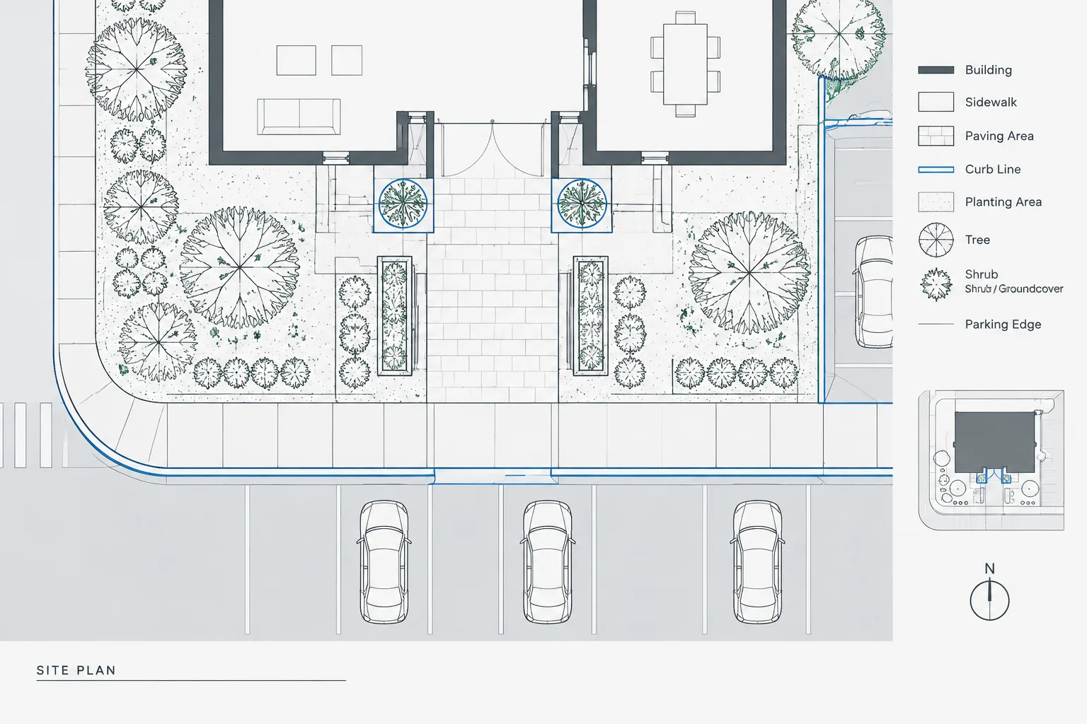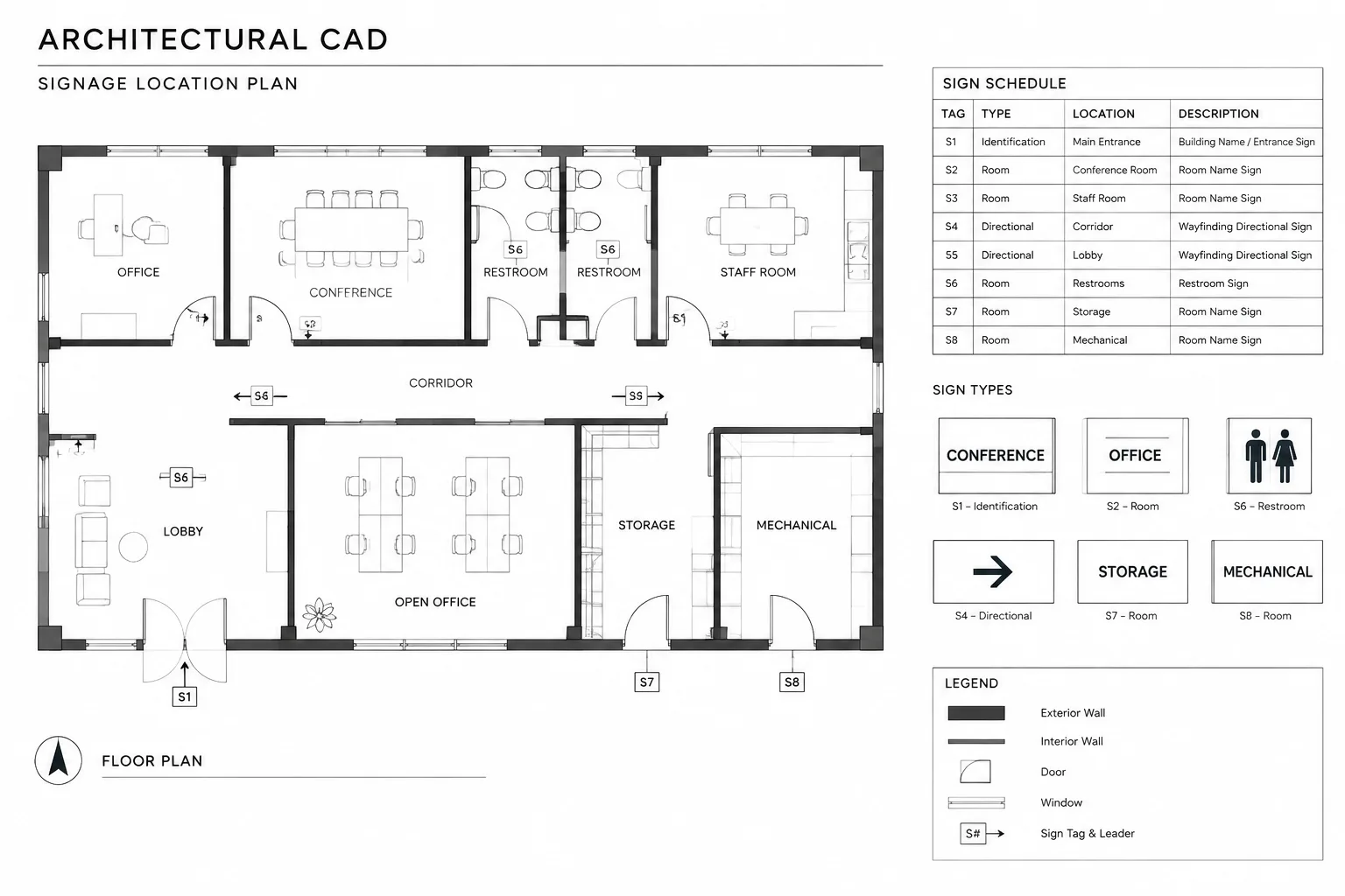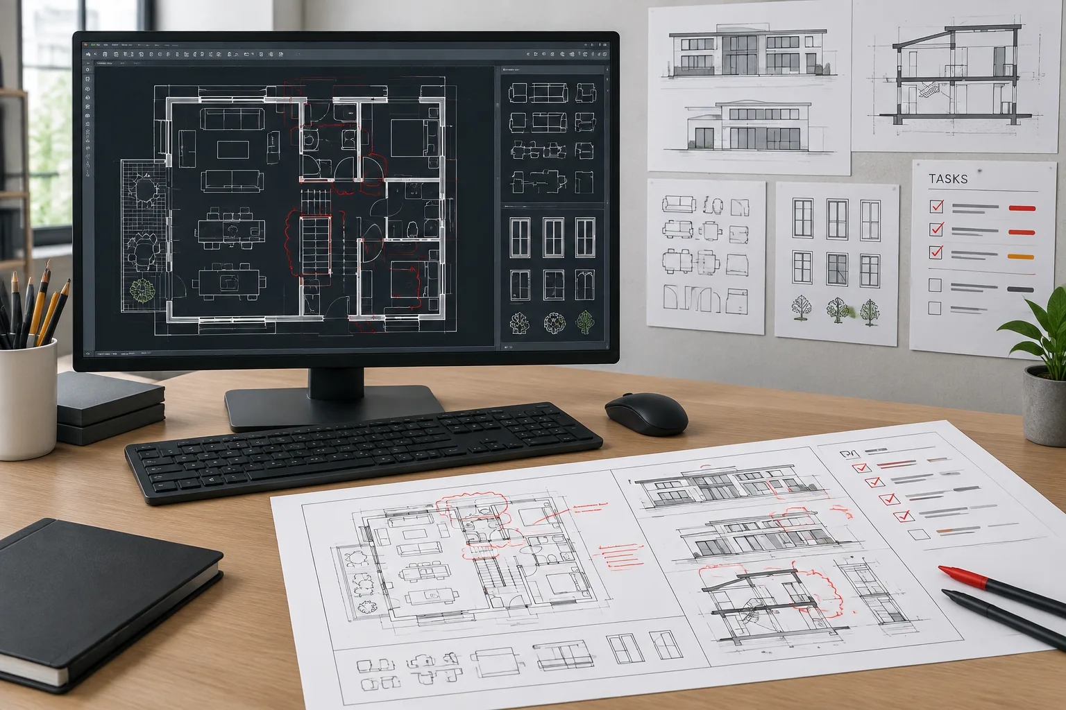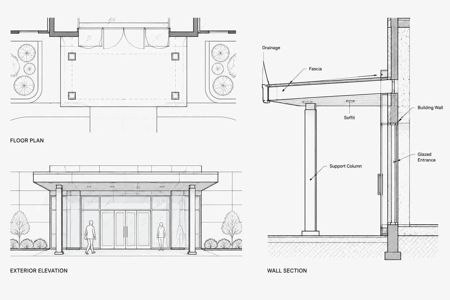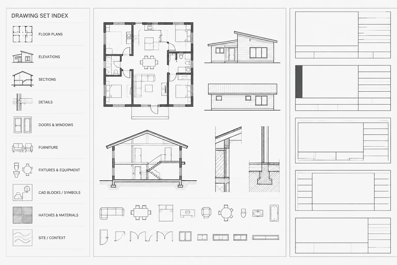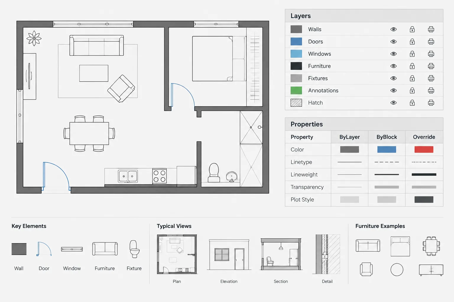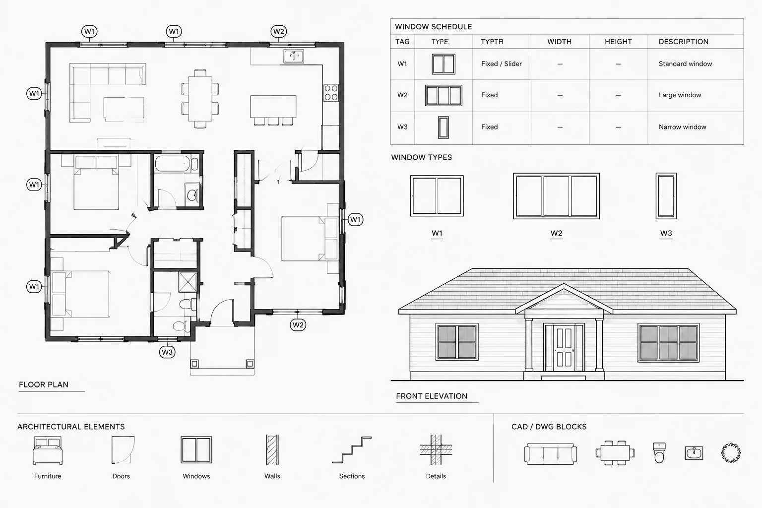
Window numbering in architectural CAD is a drawing-set coordination task, not simply an annotation exercise. Each mark must retain the same meaning wherever the opening appears, from the floor plan and elevation to the detail reference and window schedule.
This guide explains how to select an identification method, build manageable tags, coordinate repeated and mirrored conditions, and audit window information before a drawing issue. The workflow applies whether schedules are maintained manually or developed from block attributes, provided the project team defines who controls each piece of information.
Window documentation becomes difficult when the plan, elevations, details, and schedule describe the same opening in different ways. A window may appear correctly drawn in plan but carry the wrong tag, point to an outdated type elevation, or be missing from the schedule. These problems are usually not drafting errors alone; they are information-management errors.
A reliable workflow for window numbering in architectural CAD establishes what each identifier means, where it appears, and how changes move through the drawing set. The goal is not merely to add tags. It is to maintain a traceable relationship between every scheduled window and its representations throughout the project.
Decide What the Window Identifier Represents
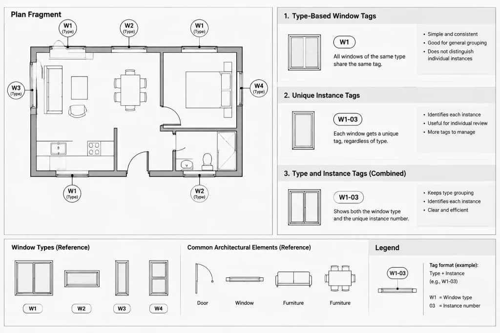
Before creating tags, determine whether the project identifies window types, individual window instances, or both. These approaches answer different questions.
Type-based identification
A type identifier groups windows that share the properties relevant to the project documentation. Multiple openings may therefore carry the same mark. This approach can keep the schedule compact, but only if the team has clearly defined which differences require a separate type.
For example, two windows that look similar in elevation may still need different identifiers if their operation, glazing, frame condition, opening size, or interface with the wall differs. Conversely, creating a new type for every location can make the schedule unnecessarily repetitive.
Instance-based identification
An instance identifier gives each scheduled opening a unique mark. This can improve location tracking and replacement coordination, particularly when openings have individual field conditions. It also produces more schedule rows and requires careful management when windows are added or removed.
Combined identification
Some projects track both a shared type and a unique opening number. The instance identifies the physical location, while the type links the opening to a common graphic or specification description. If this system is used, the two values should occupy separate fields rather than being combined into an ambiguous text string.
| Method | Useful when | Main coordination risk |
|---|---|---|
| Type-based | Many openings share documented characteristics | Important variations may be hidden under one mark |
| Instance-based | Each opening must be tracked by location | Renumbering can affect many views and records |
| Combined | Both location and repeated construction need tracking | Type and instance values may be confused |
The appropriate method depends on the project, office workflow, consultant needs, and required deliverables. It should be established before widespread tagging begins.
Create a Controlled Window Mark Structure
A window mark should be concise enough to read at the plotted scale and distinct from door numbers, room numbers, detail references, and grid bubbles. Avoid encoding too much technical information into the mark. If the identifier contains size, material, operation, floor, elevation, and sequence, a small design change can force unnecessary renumbering.
Keep descriptive information in the schedule fields and use the mark primarily as a stable reference. If prefixes are needed to distinguish categories or project areas, document their meaning in the project drafting instructions or drawing legend.
Do not assume that alphabetic marks are window types or that numeric marks are individual windows. Those conventions vary. The schedule heading and legend should make the chosen logic clear.
Build Window Tags as Manageable CAD Objects
Window tags should normally be created from a controlled block rather than assembled from loose circles, lines, and text. A block helps maintain a consistent enclosure, text position, layer assignment, and plotted appearance.
A practical tag block may include:
- A clearly defined insertion point.
- An attribute for the window mark.
- Optional separate attributes for instance and type values.
- Text alignment that accommodates expected mark lengths.
- Geometry assigned according to the office layer and property workflow.
- A visible orientation that remains readable when copied or mirrored.
Test the tag in representative viewports before deploying it across the project. A tag that looks balanced in model space may become crowded or illegible at the intended sheet scale. Also test unusually long identifiers so that they do not collide with the enclosure.
A window tag does not have to be embedded in the window graphic. Keeping the annotation separate often makes it easier to position tags clearly, control visibility by view, and reuse clean window geometry as an external reference or background.
Place Tags with a Consistent Plan Logic
Consistency makes missing and duplicated marks easier to detect. Establish a preferred placement side or relationship to the wall, then deviate only when required for clarity. Tags should not conceal mullions, wall breaks, dimensions, room names, or nearby door swings.
On crowded plans, short leaders may clarify which opening a mark references. Avoid crossing leaders or placing a tag where it could reasonably point to more than one window. Repeated windows in a continuous assembly require particular care: the drawing should make clear whether the tag applies to one unit, a grouped assembly, or every repeated unit.
Tags should also be reviewed in the actual sheet viewport. Model-space placement alone does not reveal conflicts created by viewport crops, match lines, sheet notes, or annotation from attached files.
Coordinate Plans, Elevations, and Type Drawings
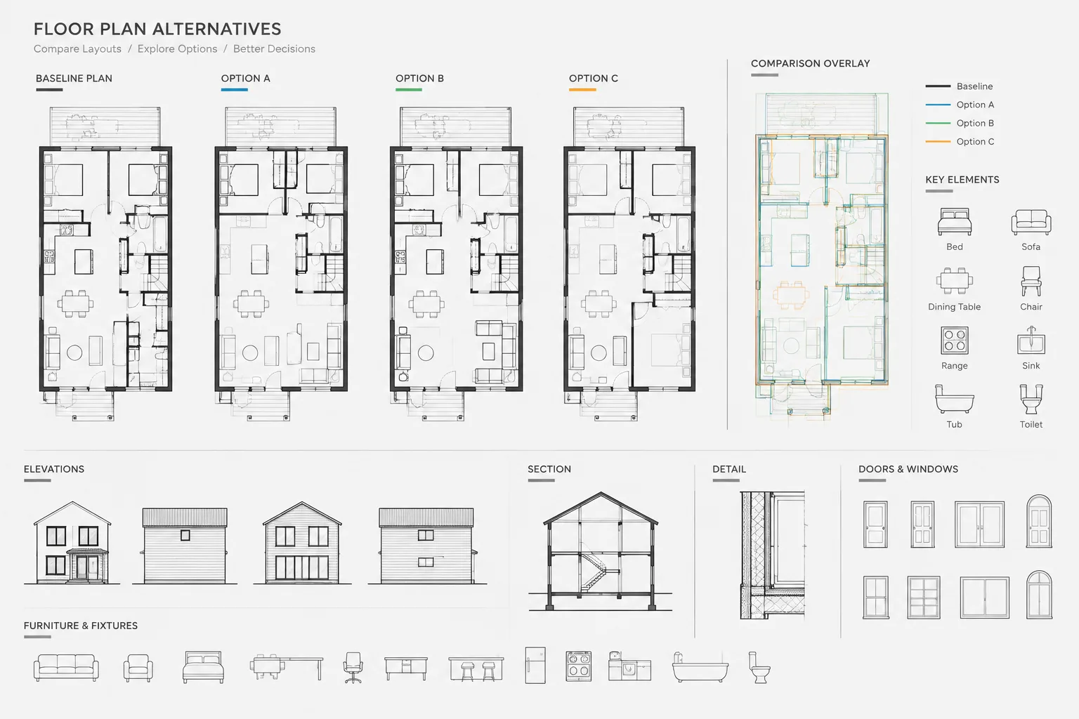
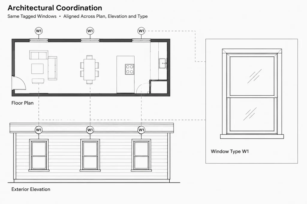
The plan usually establishes location, but it may not communicate the full window configuration. Exterior elevations, interior elevations, enlarged plans, sections, and window type elevations may all contribute information. The same identifier must have the same meaning in every view.
Use the plan as the primary location check and compare it systematically with each building elevation. Move around the building in a documented direction rather than checking views at random. For each opening, verify:
- The opening exists in both plan and the applicable elevation.
- The mark agrees wherever it appears.
- The operation and subdivision shown graphically are compatible.
- The head and sill relationships agree with relevant sections and datums.
- Grouped units are represented consistently.
- Overlapping or stacked windows are not mistaken for a single opening.
If window type elevations are included, distinguish clearly between a diagram of a typical type and a view of a specific installed assembly. A type elevation should not imply that every instance has identical surrounding construction unless that has been verified.
Develop the Schedule from Defined Data Fields
The schedule should be organized around project decisions rather than around whatever text happens to be available in the CAD block. Determine the required fields with the project team, and avoid adding columns that no one is responsible for maintaining.
Common categories may include the mark, type, location, opening description, operation, frame information, glazing reference, remarks, and applicable detail references. The exact content varies by project. Product selections, performance criteria, safety glazing decisions, egress implications, and code-related requirements must be verified by qualified project participants rather than inferred from a generic CAD symbol.
If attribute extraction or another data-assisted process is used, treat the resulting table as a coordination tool, not automatic proof of correctness. Extraction can report duplicated or missing values accurately while still preserving incorrect source information. The source blocks, schedule, and drawings require visual review.
Handle Repeated Units and Mirrored Conditions Carefully
Repeated residential units, hotel rooms, and modular bays can make window coordination appear simpler than it is. A repeated plan may be mirrored, placed on another elevation, or adjusted for a corner condition. These variations can change handing, adjacent construction, or the relationship to exterior features.
Do not automatically reuse a window mark solely because the geometry was copied. Confirm that the documented properties still match. When repeated units are externally referenced, decide whether tags belong in the source unit file or in the overall floor plan. Avoid placing the same schedule-driving tag in both locations, which can produce duplicate counts.
Manage Design Changes Without Losing Traceability
When a window changes, first decide whether it remains the same documented type. A size, operation, glazing, frame, or detail change may justify a new type, but the threshold should be consistent across the project.
When openings are deleted, avoid immediately reusing their unique numbers if doing so could confuse issued markups, field correspondence, or revision records. When a new opening is inserted, follow the project’s established sequence rather than renumbering the entire building for visual neatness. Stability is often more valuable than a perfectly continuous list.
For every window revision, check the plan tag, elevation graphics, type drawing, details, schedule row, notes, and any affected quantities. A revision is incomplete if only the most visible view has been updated.
Run a Window Coordination Audit
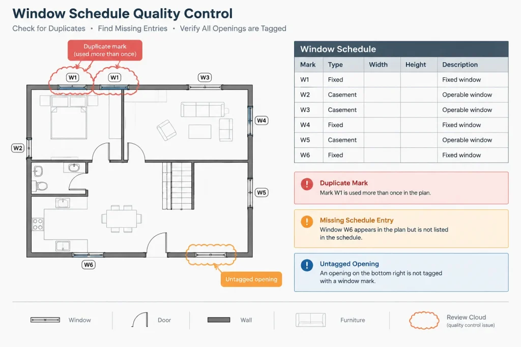
A focused audit before issue can catch problems that general drawing review misses. Perform separate passes for identity, geometry, and presentation rather than trying to evaluate everything at once.
- Find blank, placeholder, and duplicated marks.
- Confirm that each scheduled mark appears in the drawings as intended.
- Identify drawing marks that have no corresponding schedule entry.
- Compare plan opening locations with exterior elevations.
- Check that type references point to existing type drawings.
- Review copied and mirrored tags for orientation errors.
- Look for tags hidden by viewport crops, masks, or overlapping annotation.
- Check altered openings against related sections and details.
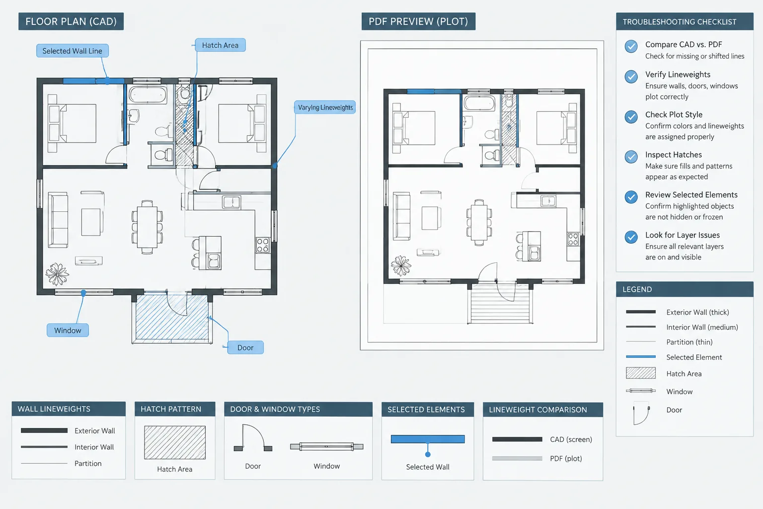
- Plot or preview representative sheets to verify readability.
Window numbering in architectural CAD works best when it is treated as a coordinated information system. Stable identifiers, controlled tag blocks, deliberate placement, and repeatable cross-checks allow plans and schedules to remain useful as the design evolves. The schedule then becomes more than a table: it becomes an index connecting each opening to the drawings and decisions that define it.
Establish Information Ownership Before Production
A coordinated window workflow needs an agreed source for each decision. The plan may control location, a type drawing may control configuration, and the schedule may contain descriptive data, but conflicting information should never be resolved by assumption. Assign responsibility for approving marks, type changes, schedule fields, and graphic revisions.
It is useful to maintain a working register that distinguishes confirmed openings from items awaiting design input. This prevents provisional information from appearing complete simply because it has been placed in a polished schedule. Unresolved entries should use a consistent review status rather than an invented product description or an unverified technical requirement.
Use a Repeatable Change-Control Path
When an opening changes, review the effect in a consistent order:
- Identity: Determine whether the existing mark and type remain valid.
- Location: Confirm the affected plan, elevation, room, wall, or repeated unit.
- Representation: Update every graphic view that depicts the opening.
- Schedule data: Revise only the fields affected by the approved change.
- References: Check related type drawings, details, notes, and callouts.
- Presentation: Review the plotted sheet for tag conflicts and readability.
This sequence helps separate a graphic adjustment from a documentation change. Moving annotation for clarity does not necessarily alter the window, while changing operation or construction may affect several records even when the plan symbol looks similar.
Keep Coordination Evidence Reviewable
Automated extraction, comparison lists, and visual markups can support quality control, but the review method should remain understandable to another team member. A reviewer should be able to determine why a mark exists, what it identifies, and whether a discrepancy has been resolved.
Before issue, compare the current schedule against the current drawing backgrounds rather than relying on an earlier export. Archive or clearly identify obsolete working schedules so they are not mistaken for active project information. This administrative discipline is essential when several people edit plans, elevations, and schedules in separate files.
Frequently Asked Questions
Should every window have a unique number?
Not necessarily. A project may identify shared window types, individual installed openings, or both. The selected method should match the required level of location tracking and should be explained consistently in the schedule and drawing legend.
What should happen when a plan tag and schedule disagree?
Do not correct one location by assumption. Check the approved design information, relevant elevations, type drawings, details, and revision records. Once the intended condition is confirmed, update every affected representation and repeat the coordination check.
Should window tags be included inside window blocks?
They can be, but separate annotation often provides better control over placement, visibility, and sheet readability. The important issue is avoiding duplicate schedule-driving information and maintaining a clear relationship between the tag and the opening.
How should tags be handled in externally referenced repeated units?
Choose whether the controlling tags belong in the unit source file or the overall plan file. Avoid maintaining active versions in both places. Mirrored and modified units should still be checked individually because copied geometry does not guarantee identical documented conditions.
Is attribute extraction enough to validate a window schedule?
No. Extraction can collect the values stored in blocks, but it cannot establish that those values correctly represent the design. Use extracted data to identify omissions, duplicates, and inconsistencies, then verify the findings against the drawings and approved project information.
When should an existing window mark be retired?
A mark may need to be retired when its opening is removed or when the project’s identification logic requires a replacement. Avoid immediate reuse when it could create confusion with issued drawings, markups, correspondence, or revision history.