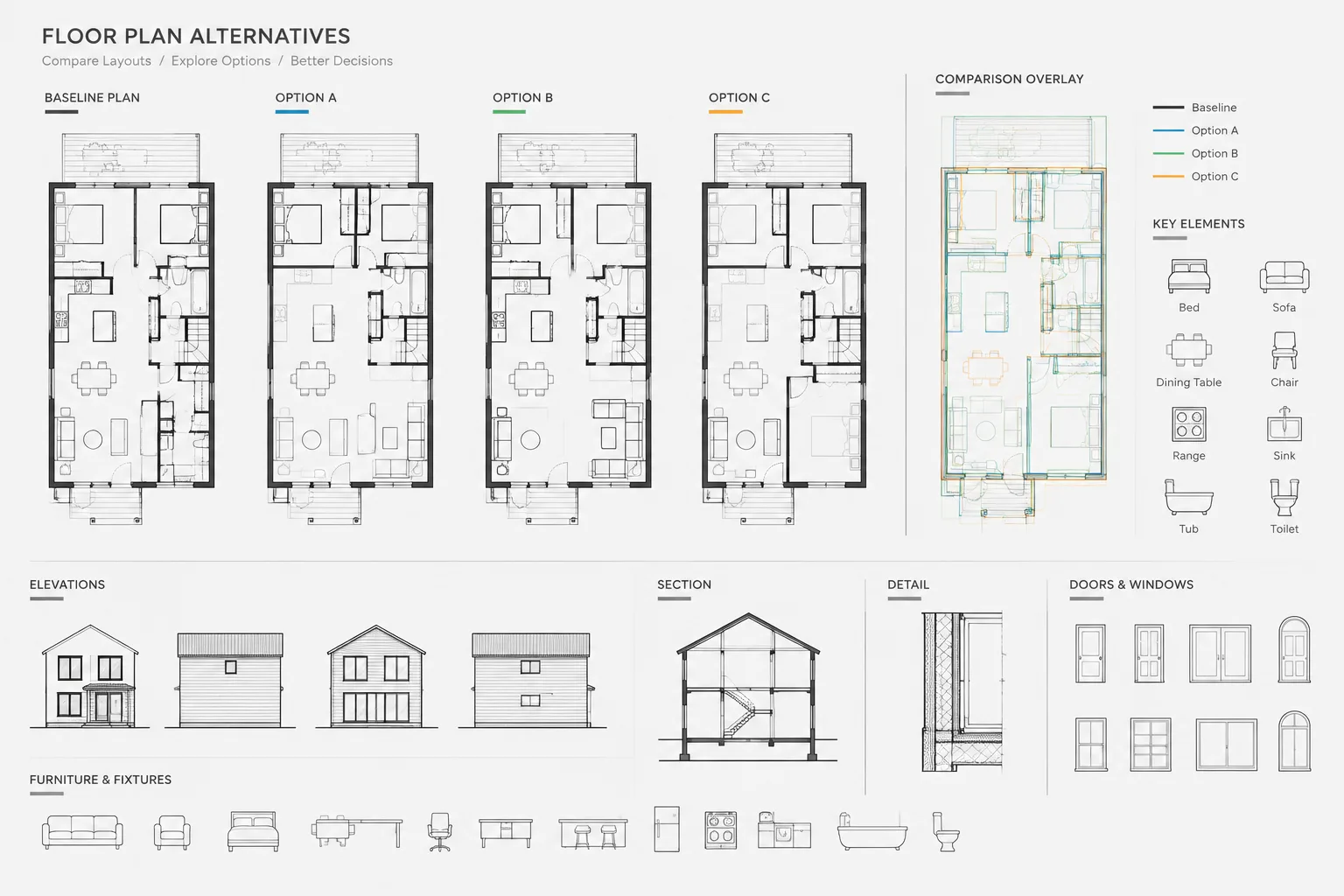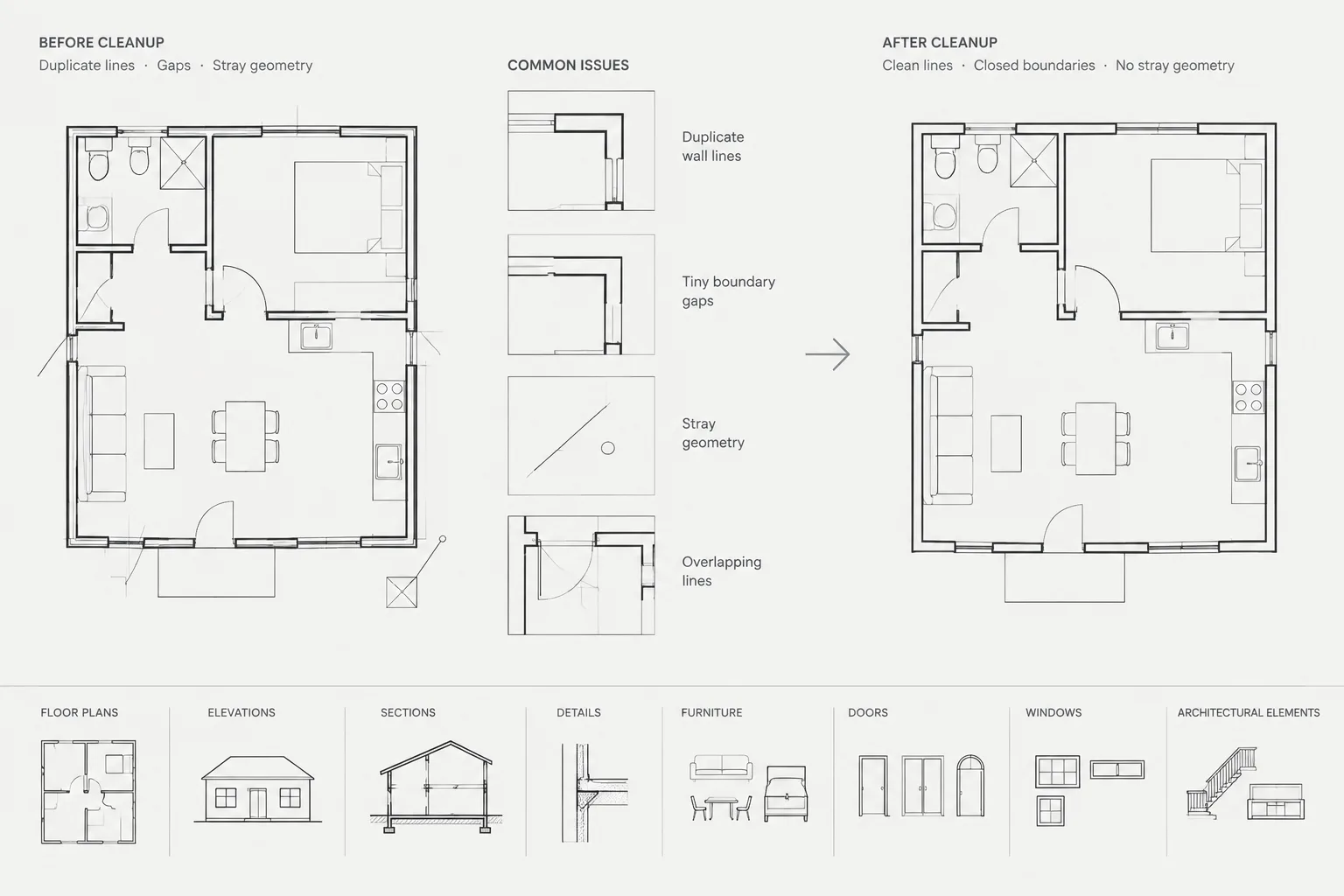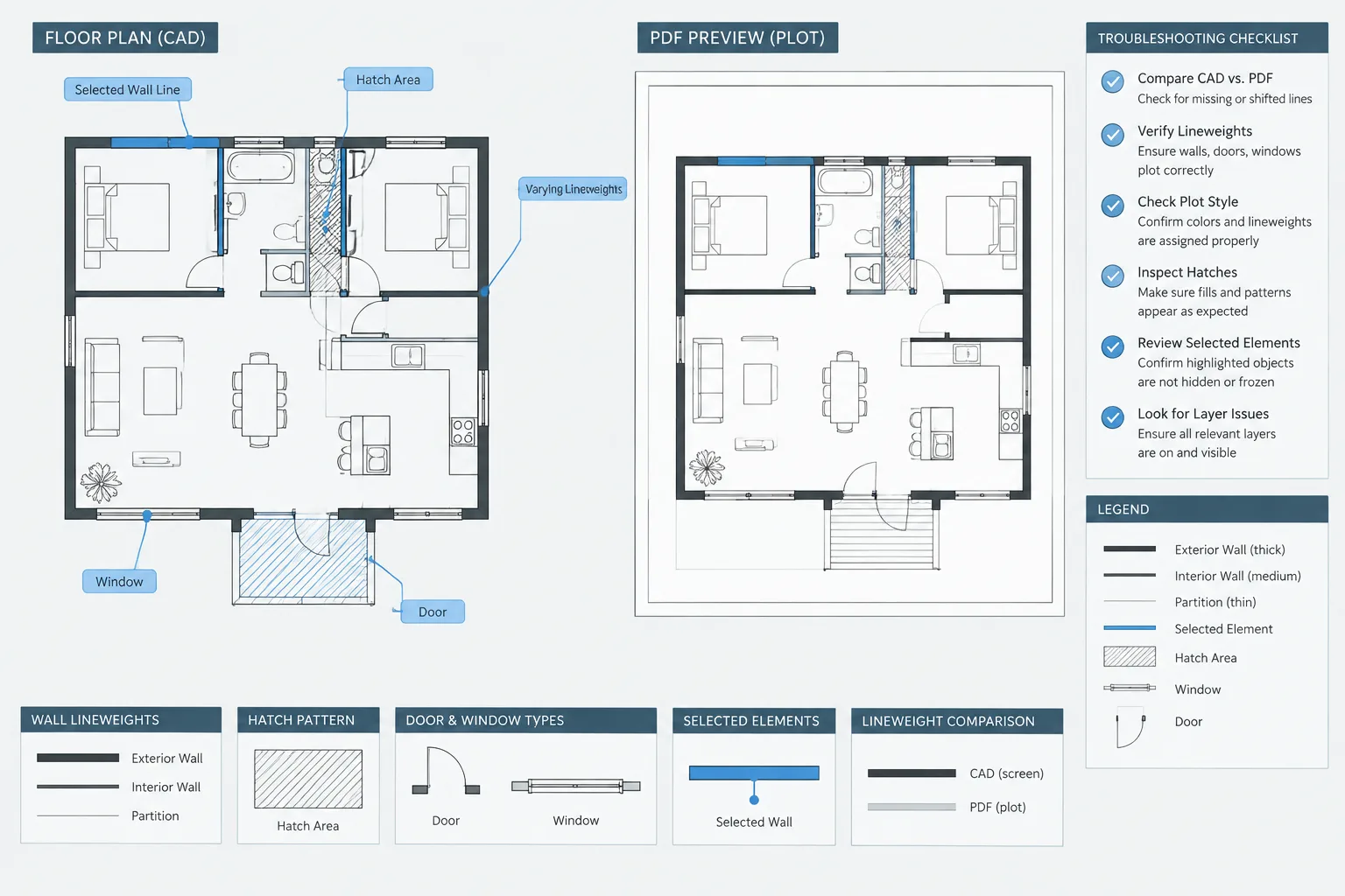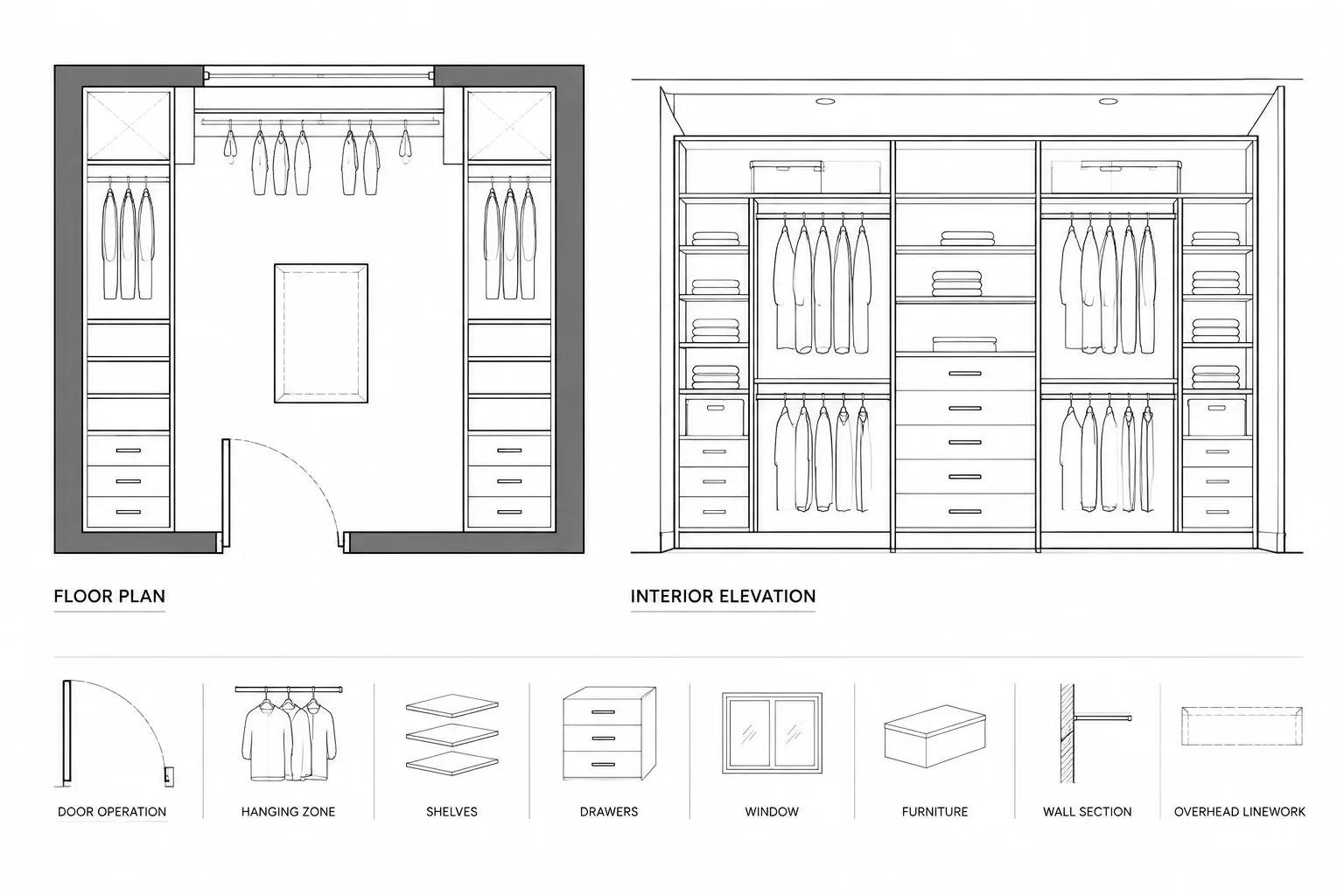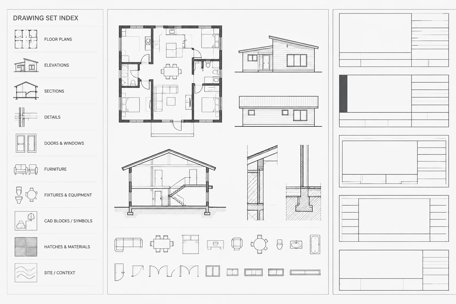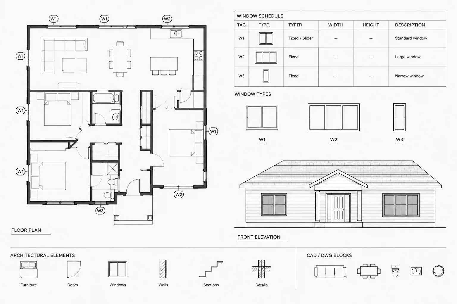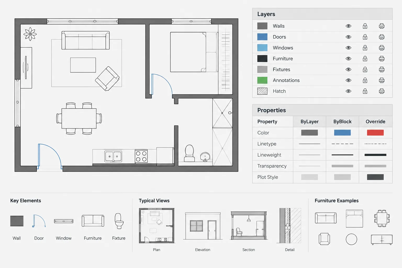
Where annotation lives affects far more than appearance. It determines how dimensions, tags, callouts, leaders, and notes respond when geometry changes, viewports are adjusted, or sheets are reorganized.
This guide compares model-space, paper-space, and hybrid annotation workflows by function. The goal is to help CAD teams establish predictable ownership, visibility, revision, and quality-control rules rather than relying on individual drafting habits.
Architectural CAD annotation can be placed in model space, paper space, or a controlled combination of both. Each approach can produce a clear drawing set, but inconsistency creates familiar problems: duplicated notes, dimensions that appear at the wrong size, tags that drift away from objects, and annotations that show through unintended viewports.
The best choice is not simply a software preference. It depends on what the annotation describes, how many sheets display the geometry, whether a view is rotated or enlarged, and how the project team manages revisions. A reliable architectural CAD annotation workflow begins by defining where each category of information belongs.
Understand the Two Drawing Environments
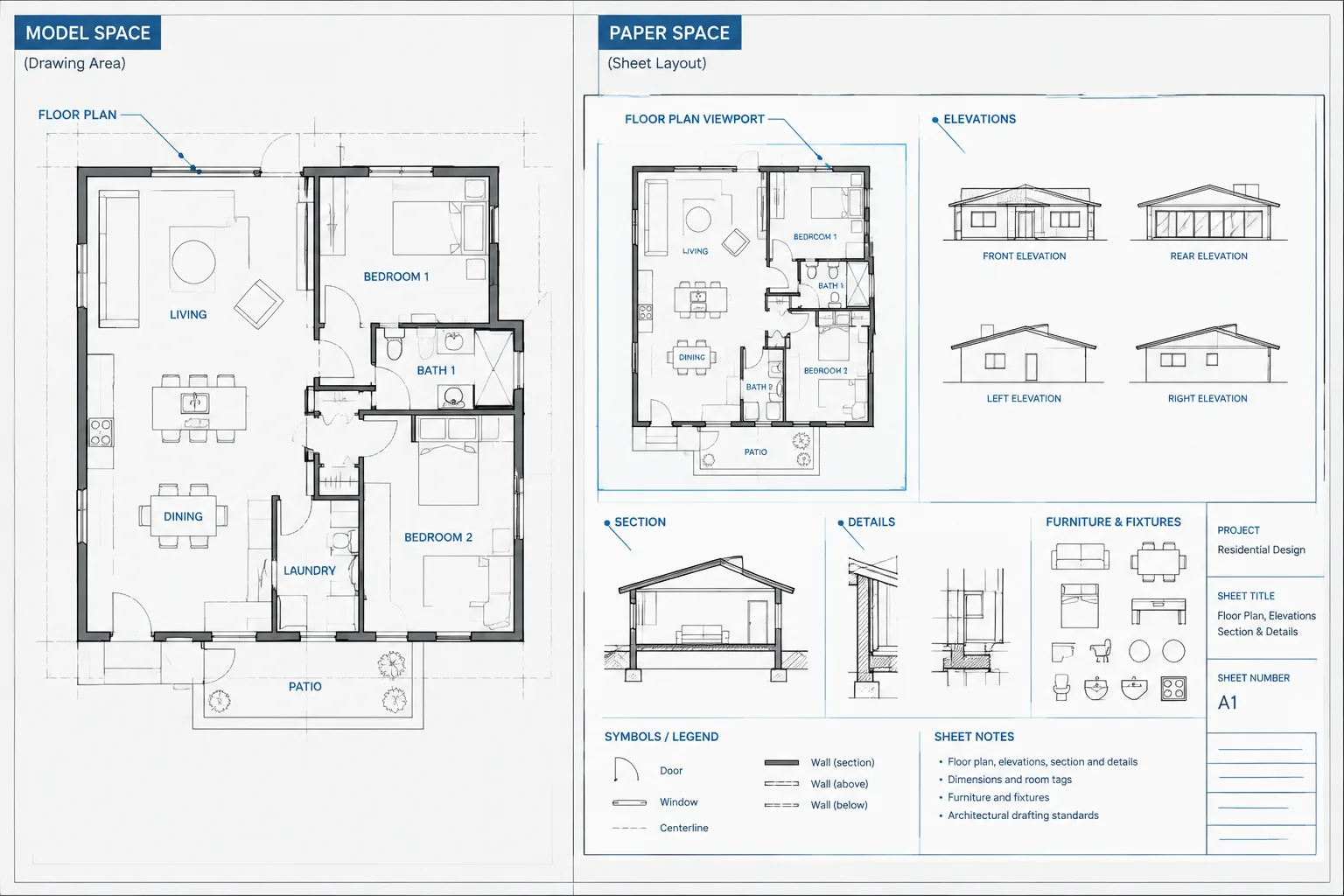
Model space
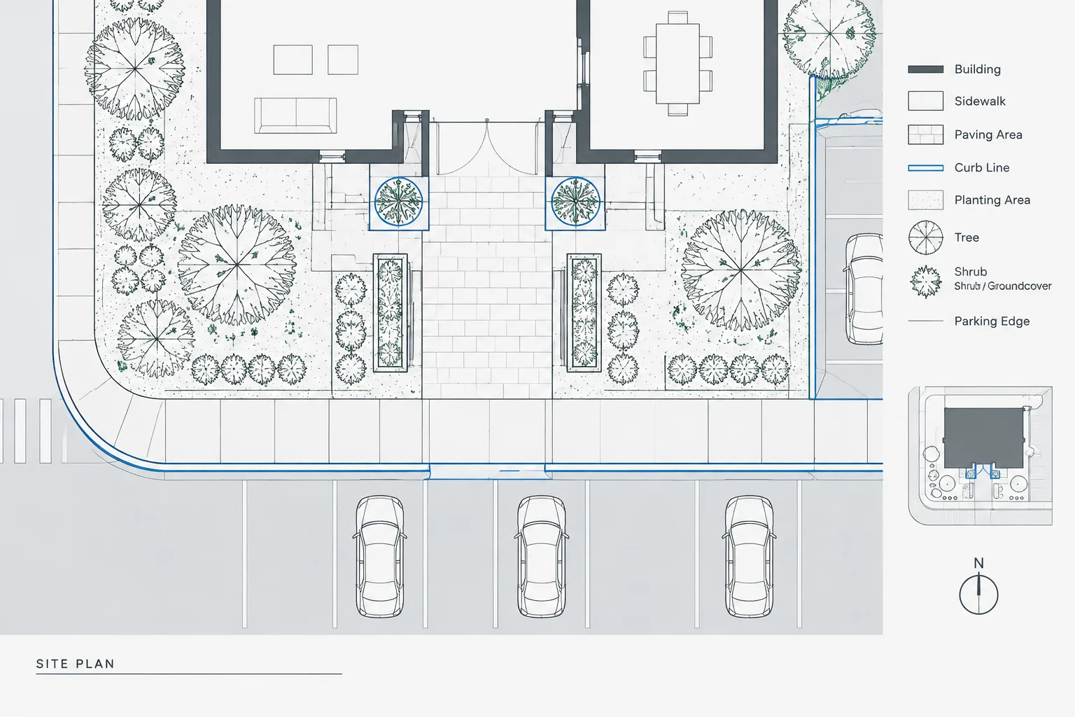
Model space normally contains the building, site, details, and other project geometry at full size. Annotation placed here exists alongside the objects it describes. A room tag can remain within its room, a dimension can stay associated with a wall layout, and a section marker can move with the plan geometry during design development.
Model-space annotation may be created at a size intended for a particular plotted scale, or it may use annotative behavior so that its displayed size responds to assigned annotation scales. Either method requires deliberate setup and testing.
Paper space
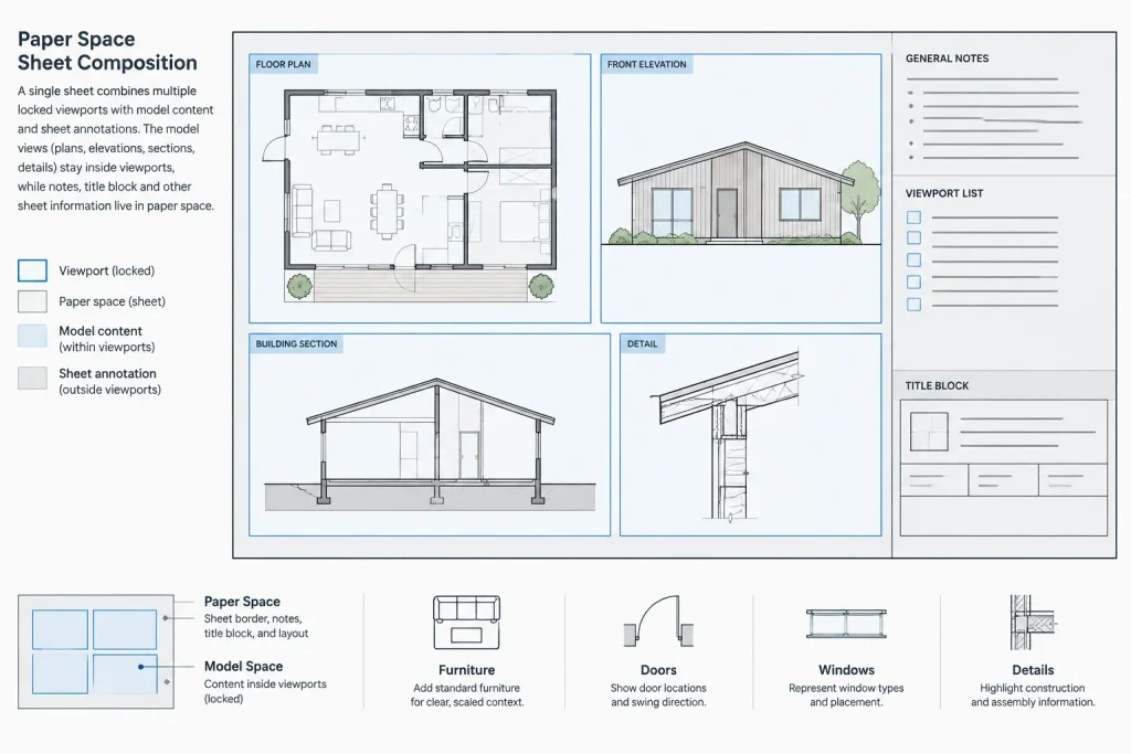
Paper space represents the drawing sheet. It commonly contains the title block, sheet-specific notes, viewport arrangement, issue information, and other content related to the final printed or exported page. Viewports display selected portions of model space at controlled scales.
Paper-space annotation is drawn at its final sheet size. This makes plotted text height and graphic spacing easier to judge, but the annotation is separated from the model geometry it references.
When Model-Space Annotation Works Well
Model space is often appropriate when an annotation is closely tied to a physical object or location. Typical candidates include:
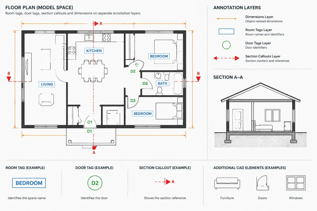
- Plan dimensions connected to walls, openings, grids, or fixtures
- Room names, room tags, and area identifiers
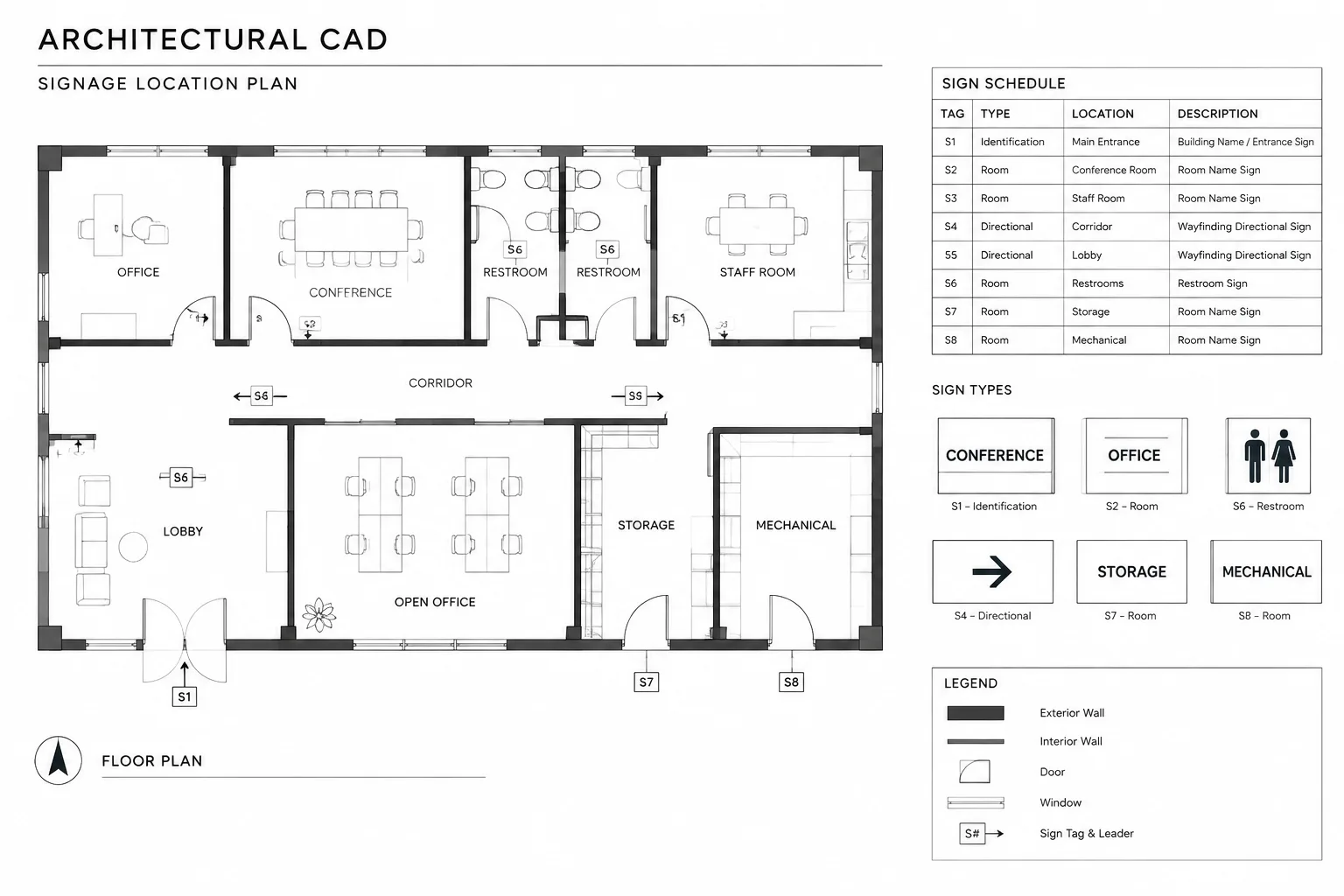
- Door, window, wall-type, and equipment tags
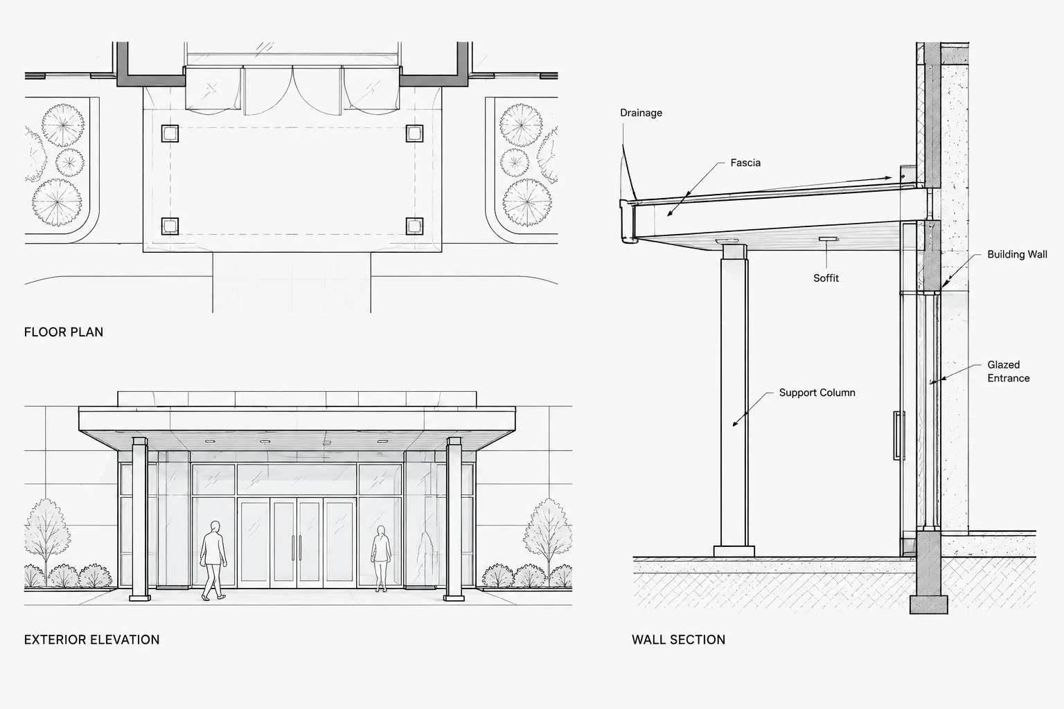
- Section, elevation, and detail callouts positioned in a plan
- Level markers and datum-related notes in elevations or sections
- Notes that must remain attached to a specific construction condition
This approach keeps the annotation near the geometry during editing. If a doorway moves, its tag and related dimensions are visible while the change is being made. Reviewers can inspect the model-space composition without opening every sheet layout.
Model-space annotation is also useful when the same annotated view appears on more than one sheet. However, this benefit becomes a liability if different sheets need different note content. Viewport-specific layer control or separate annotation layers may then be required.
Risks of model-space annotation
The main challenge is scale management. Text, symbols, leaders, and dimension components must plot consistently even when views use different scales. Common failure modes include:
- Annotation that is readable in one viewport but too large or too small in another
- Tags appearing in viewports where they are not relevant
- Multiple copies of the same note created for different scales
- Incorrect annotation scales assigned to objects
- Dimensions crossing viewport crop boundaries
- Rotated views producing awkward text or leader orientation
A model-space system therefore needs clear text and dimension styles, disciplined layer naming, and a defined method for controlling scale-dependent visibility.
When Paper-Space Annotation Is the Better Choice
Paper space is generally suitable for information that belongs to the sheet rather than to the building model. Examples include:
- Sheet titles and viewport titles
- General sheet notes
- Issue notes and revision-related graphics
- Graphic scales associated with individual views
- Sheet-level legends and abbreviations
- Notes describing how views are arranged or presented
- Simple labels that apply only to one viewport presentation
Because paper-space objects are composed directly on the sheet, the drafter can evaluate their final graphic size without translating between model scale and plotted scale. This is especially useful for sheet notes, titles, and diagrammatic explanations that do not need to follow model geometry.
Risks of paper-space annotation
Paper-space dimensions and leaders can appear correctly while no longer matching the underlying model. A viewport may be panned, rescaled, or replaced, leaving the annotation pointing to the wrong feature. Sheet-space notes can also hide model changes because the drafter sees the label but not the connection between that label and the edited object.
Avoid using paper space as a convenient place to repair an uncoordinated model-space view. Manually covering errors, drawing replacement linework over a viewport, or adding dimensions that are not checked against full-size geometry can make later revisions difficult to audit.
A Practical Hybrid Strategy
Many architectural teams use a hybrid workflow. The key is to divide annotation by purpose rather than placing objects wherever they are easiest to draw.
| Annotation category | Typical location | Reason |
|---|---|---|
| Object-related dimensions and tags | Model space | They remain connected visually and logically to building geometry. |
| Plan, section, and elevation callouts | Model space | The marker identifies a location or viewing direction in the model. |
| Viewport titles and sheet references | Paper space | They describe the sheet presentation and viewport arrangement. |
| General sheet notes | Paper space | They apply to the sheet rather than one modeled location. |
| Detail-specific notes | Usually model space | They should move and revise with the detail linework. |
| Revision clouds and markers | Project-defined | Placement depends on whether the revision tracks model content, sheet presentation, or both. |
This division is a starting point, not a universal rule. The important requirement is that everyone working on the project can predict where an annotation should be found and edited.
Build the Workflow Before Annotating
1. Classify annotation by function
Create a short project rule covering dimensions, tags, keynotes, callouts, view titles, general notes, and revisions. Decide whether each category is model-based, sheet-based, or conditional. Record exceptions rather than relying on individual memory.
2. Separate annotation with layers
Use layers that identify annotation purpose clearly. Avoid putting all text, dimensions, symbols, and leaders on one generic layer. Functional separation makes it easier to control viewport visibility, issue consultant backgrounds, and troubleshoot plots.
3. Standardize styles
Define approved text, dimension, multileader, and table styles for the project. Remove unnecessary imported styles before they spread through the drawing set. Naming should communicate intended use without depending on unexplained personal abbreviations.
4. Plan for repeated and enlarged views
A floor plan may appear as an overall plan, an enlarged room plan, and a background in a consultant sheet. Determine whether each view needs the same annotation or a different level of detail. Separate layers, dedicated view files, or annotative visibility may be appropriate depending on the project structure.
5. Lock established viewports
Once a viewport is positioned and assigned its intended scale, lock it according to the office workflow. This reduces accidental zooming and panning that can disconnect paper-space labels from displayed geometry.
Coordinate Annotation Across Xrefs
External references complicate annotation ownership. A base plan may be referenced into several sheet files, while tags and dimensions are either stored with the base or added separately in each sheet.
Keeping shared annotation with the referenced plan can improve coordination, but it may expose unwanted information in other host drawings. Keeping annotation in sheet files gives each sheet more control, but it can create repeated work and disconnected edits.
Before choosing, ask three questions:
- Does the annotation need to appear in multiple host drawings?
- Who is responsible for editing and checking it?
- Will another discipline receive the file as a clean background?
Consultant backgrounds should not carry avoidable sheet notes, viewport titles, or irrelevant tags. Layer-based separation and a documented export process help keep shared files usable.
Quality-Control Checks Before Issue
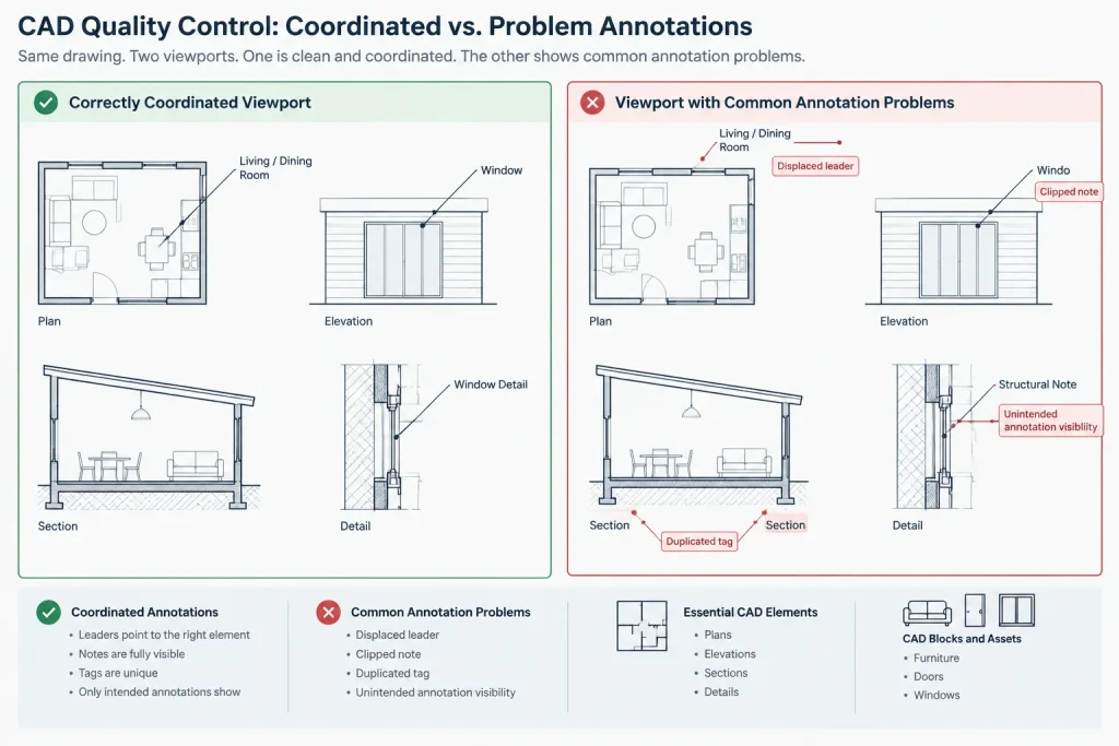
Review annotation in the same context in which it will be delivered. A model-space inspection alone cannot confirm sheet composition, and a paper-space review may miss duplicated or hidden objects.
- Plot or export every sheet using the intended plot configuration.
- Check text, dimensions, leaders, and symbols at the final viewing size.
- Confirm that viewport scales and positions have not changed unexpectedly.
- Look for model-space notes appearing through unintended viewports.
- Verify that paper-space leaders still point to the correct model features.
- Compare tags and callouts against schedules, drawing references, and view titles.
- Inspect rotated and enlarged views for text orientation problems.
- Turn off or freeze temporary markup and working-note layers.
- Check that no annotation is hidden outside a viewport boundary.
Choose Consistency Over Preference
Model space is usually strongest for annotation tied directly to architectural geometry, while paper space is strongest for information tied to sheet presentation. A hybrid approach often provides the clearest result, provided its rules are explicit.
The most important decision is not whether every note belongs in one environment. It is whether annotation can be found, revised, checked, and plotted predictably by the entire team. A documented architectural CAD annotation workflow reduces rework and keeps drawing information aligned with both the building model and the final sheets.
A Simple Decision Test for New Annotation
Before placing an annotation object, identify what it belongs to. If it describes a wall, opening, room, fixture, datum, or detail condition, it usually has a strong relationship to model geometry. If it describes the sheet, viewport arrangement, issue, or presentation, it usually has a stronger relationship to paper space.
Then consider whether the information must appear in several views. Shared annotation may benefit from being maintained with the geometry, while view-specific commentary may need separate control. The correct location is the one that makes ownership and editing predictable without creating unnecessary copies.
Test the revision path
Imagine that the referenced geometry moves, the viewport is panned, or an enlarged view is added. Ask which annotation objects must be reviewed and where a drafter would reasonably expect to find them. If the answer is unclear, the project rule needs more definition.
Assign ownership as well as location
Location alone does not prevent coordination errors. The team should also identify who maintains each annotation category, especially when base drawings, external references, and separate sheet files are involved. Clear ownership reduces the chance that one person updates geometry while another assumes the related tags or notes were revised automatically.
Use Exceptions Deliberately
Some drawings require exceptions because of repeated views, rotated presentations, consultant backgrounds, or project-specific issue procedures. An exception is manageable when it is documented, placed on an identifiable layer, and reviewed in its plotted context.
Avoid solving a local graphic problem in a way that obscures the information source. If an annotation must be moved to another environment, record why it is different and confirm that future editors can locate it. Predictability is more valuable than forcing every project into an absolute model-space-only or paper-space-only rule.
Audit the System During Revisions
Revision reviews should examine annotation relationships, not just spelling and graphic appearance. Compare changed geometry with nearby dimensions, tags, callouts, keynotes, and leaders. Also review sheets affected indirectly by referenced files or repeated views.
- Search for duplicated annotations serving the same purpose.
- Confirm that view-specific notes are not visible in unrelated viewports.
- Check whether deleted or moved geometry has left orphaned tags and leaders.
- Review layer overrides and visibility controls for unintended differences.
- Confirm that sheet-based labels still match the views they describe.
This audit turns the annotation policy into a repeatable coordination practice rather than a one-time setup decision.
Frequently Asked Questions
Should all architectural dimensions be placed in model space?
Not necessarily. Dimensions tied directly to building geometry are commonly managed in model space because their relationship to the objects is easier to inspect. A project may use a different method for view-specific or sheet-specific information, but the exception should be documented and checked after viewport changes.
Is paper-space annotation easier to plot consistently?
Paper-space text and graphics are composed at their final sheet size, which makes their visual appearance easier to assess. That advantage does not remove the need to verify leaders, dimensions, and labels against the model shown through each viewport.
When is a hybrid annotation workflow appropriate?
A hybrid workflow is appropriate when geometry-related information and sheet-presentation information have different coordination needs. It works best when annotation categories, layers, styles, ownership, and exceptions are defined before production drafting begins.
How should annotation be handled when the same plan appears on several sheets?
Determine whether every sheet needs identical information. Shared tags or callouts may be maintained with the plan, while sheet-specific notes may require separate layers or paper-space placement. Review each viewport to prevent irrelevant annotation from appearing.
Why do paper-space leaders become unreliable?
A paper-space leader can remain stationary while the viewport content is panned, rescaled, replaced, or reorganized. The leader may still look intentional even though its target has changed, so viewport modifications should trigger an annotation review.
What is the most important rule for architectural CAD annotation?
Every annotation category should have a predictable location, responsible editor, visibility method, and checking process. Consistency allows the team to find and revise information without guessing.