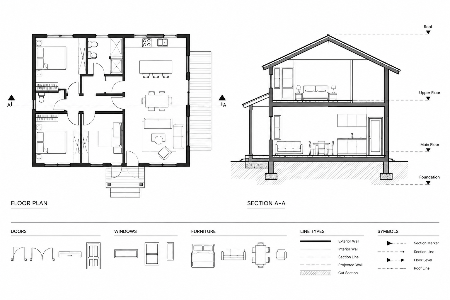
An architectural section explains a building by showing it as though a vertical plane has cut through the walls, floors, roof, openings, stairs, and interior spaces. Unlike an elevation, which primarily shows visible exterior or interior surfaces, a section reveals relationships that cannot be understood from the floor plan alone.
Creating an accurate architectural section drawing in CAD is not simply a matter of projecting lines upward from a plan. The drafter must decide what is cut, what is seen beyond the cut, which elements require emphasis, and how the drawing will coordinate with other sheets. The following workflow is suitable for schematic drawings, design development, permit documentation, and drawing exercises, although the required content and level of detail will vary by project.
Start with the purpose of the section
Before drawing, identify what the section needs to communicate. A general building section may explain floor-to-floor relationships and the overall roof form. A wall section may focus on assemblies and material transitions. An interior section may clarify ceiling changes, casework, fixtures, or built-in elements.
A useful section cut often passes through important features such as:
- Stairs, ramps, or changes in floor level
- Doors and windows that need vertical coordination
- Double-height rooms, atriums, or mezzanines
- Roof slopes, parapets, dormers, or overhangs
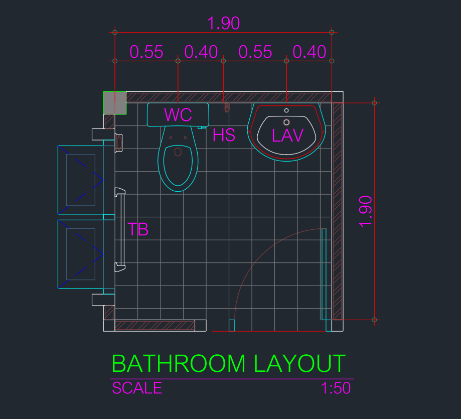
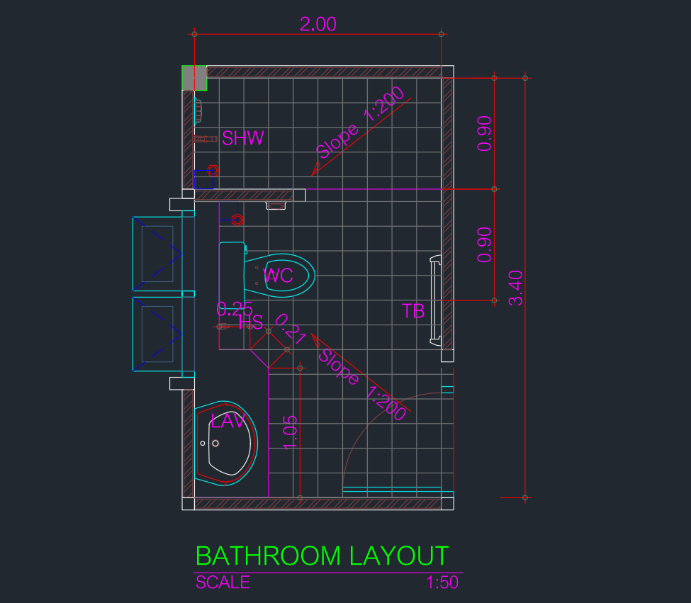
- Kitchen, bathroom, or service zones requiring coordination
- Changes in wall construction or exterior materials
- Areas where the spatial relationship is unclear in plan
Avoid placing the cut line through an uninformative portion of the building merely because it is geometrically convenient. The best section is selected for the information it reveals.
Place and identify the section line on the floor plan
Draw the section line on the corresponding floor plan and add directional markers at its ends. The viewing direction determines which elements will appear beyond the cut plane. Give the section a consistent identifier and provide the destination sheet reference when the drawing set has established sheet numbers.
If the cut changes direction, use offsets carefully. An offset section can capture several important spaces, but excessive jogs may create a misleading representation. Make each change in the cutting plane visually clear, and avoid implying that separated objects occupy the same physical plane.
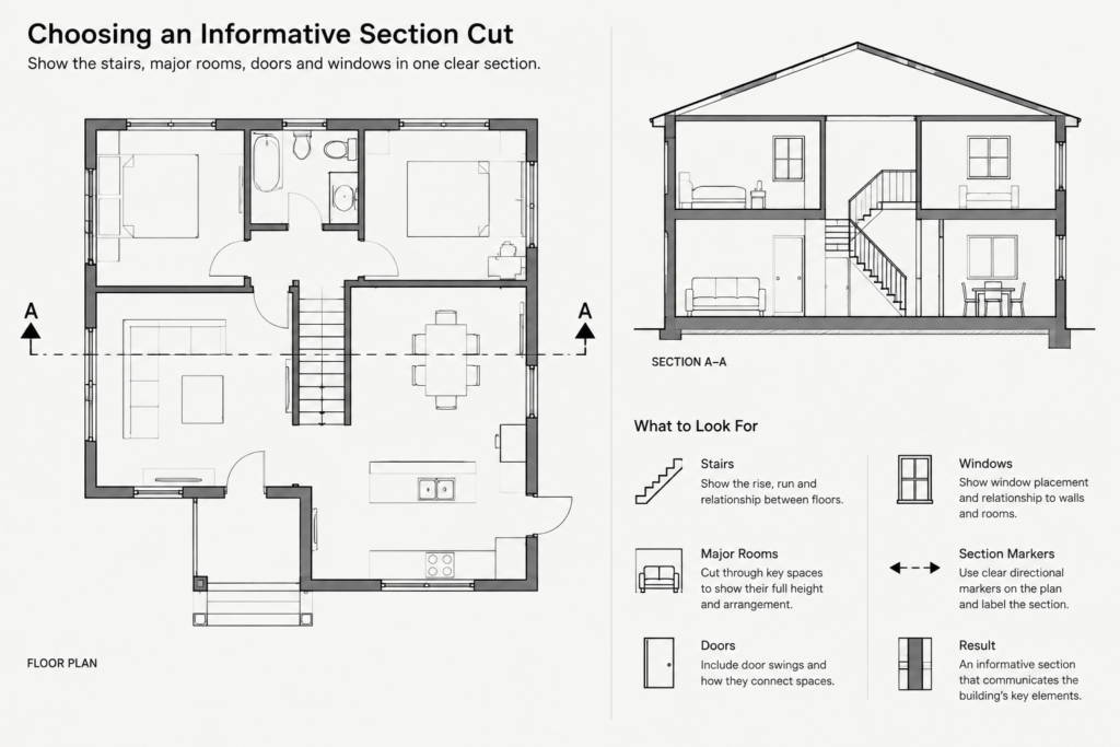
Check the section marker on every affected plan. In a multistory building, the cut may need to be shown on more than one level so readers can understand its path through the entire structure.
Prepare the CAD file before projecting geometry
Confirm that the floor plans are aligned and drawn at the intended real-world size. Upper and lower plans should share a dependable reference point, such as a grid intersection, structural bay, or agreed project origin. Misaligned plans produce sections with shifted walls, openings, and stairs.
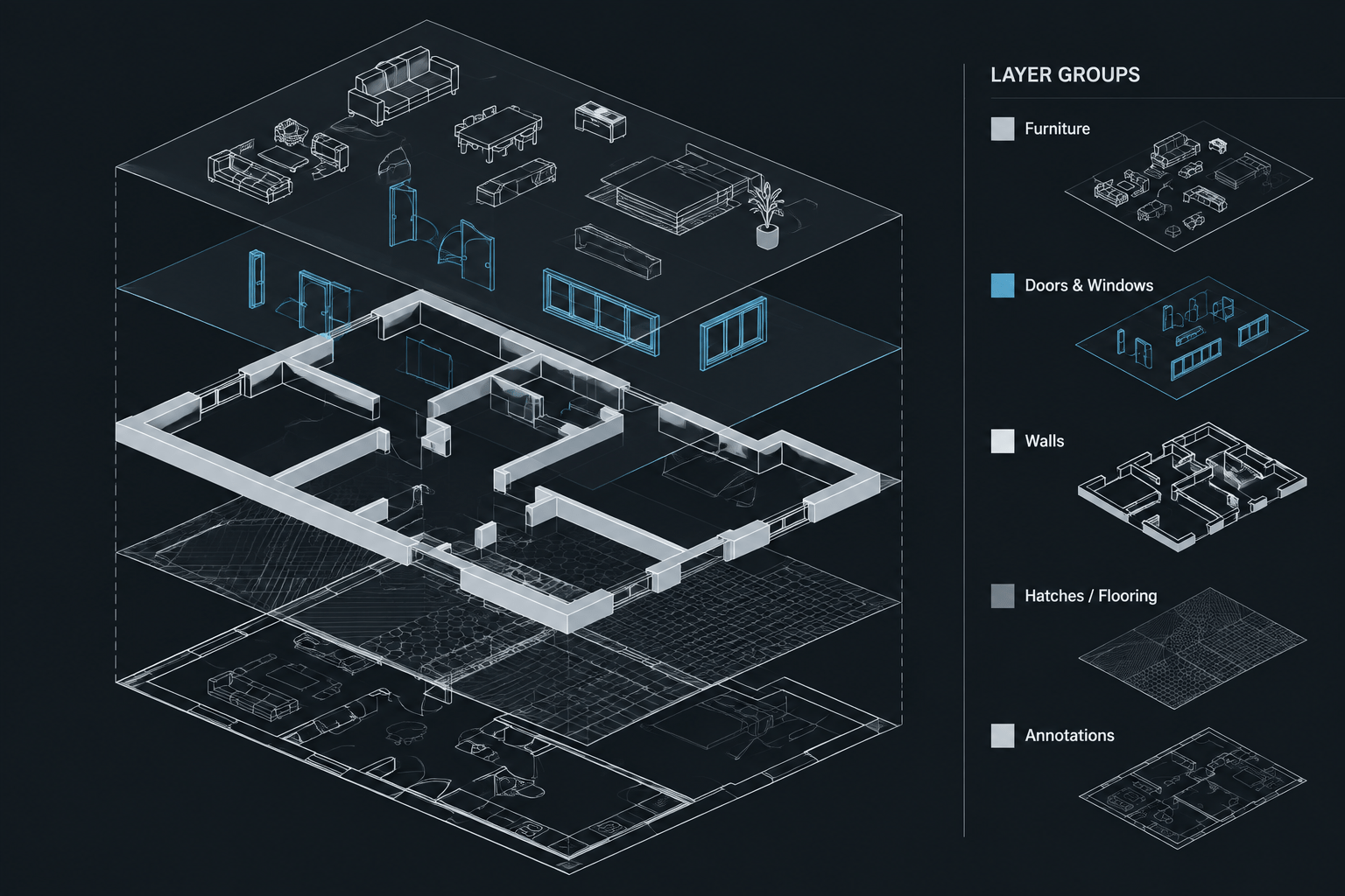
Organize section information on appropriate layers. The exact naming system should follow the project CAD standard, but separate controls are commonly useful for cut elements, objects beyond the cut, overhead elements, hatches, annotations, dimensions, level markers, and reference construction lines.
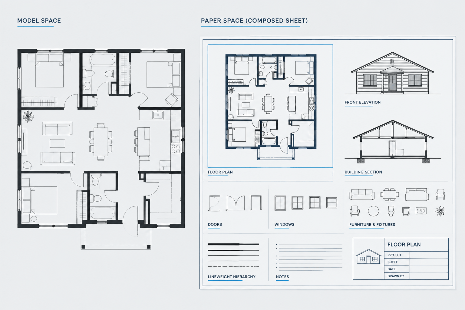
If plans are attached as external references, keep the section geometry in a dedicated drawing file rather than tracing into an unrelated sheet file. This helps separate model content from sheet presentation and reduces duplicated information. Confirm that referenced files are current before beginning major revisions.
Establish levels and horizontal datums
Begin the section with the primary vertical reference information. Draw horizontal construction lines for relevant floor levels, landings, roof reference points, ceilings, and other important datums. Label only the levels that help explain the building or are required by the drawing set.
Floor plans primarily describe horizontal location, while sections describe vertical location. A wall visible on plan cannot be placed correctly in section until its base, top, and relationship to adjacent construction are understood. If a height has not been resolved, do not guess. Flag it for design coordination or use clearly identified preliminary information according to the project workflow.
Project the cut elements from the plan
Use temporary projection lines to transfer wall faces, columns, openings, stairs, and other relevant geometry from the plan to the section. Projection lines are drafting aids and should remain on a nonplotting or easily controlled construction layer.
Draw the elements intersected by the cutting plane first. Depending on the section location, these may include:
- Exterior and interior walls
- Floor and roof assemblies
- Foundations or below-grade construction
- Columns, beams, or structural zones
- Stair runs and landings
- Doors, windows, and framed openings
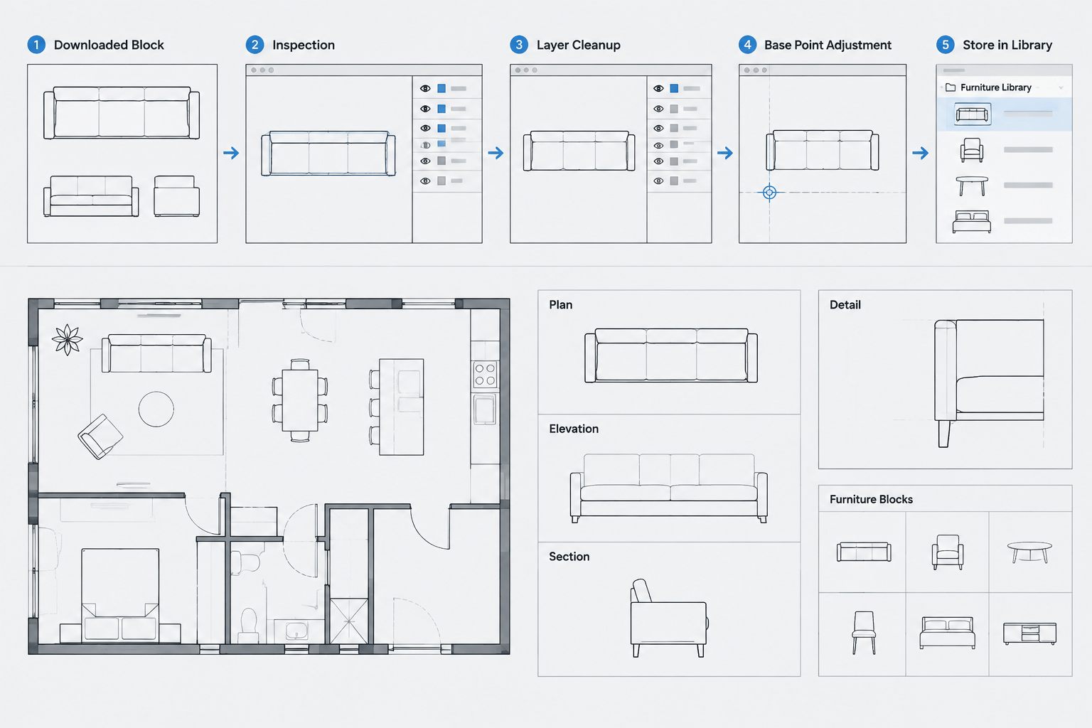
Represent only information supported by the project documents. Generic downloaded blocks can be useful as drafting references, but their profiles, frame depths, sill conditions, and other characteristics must be checked before they are incorporated into a real project.
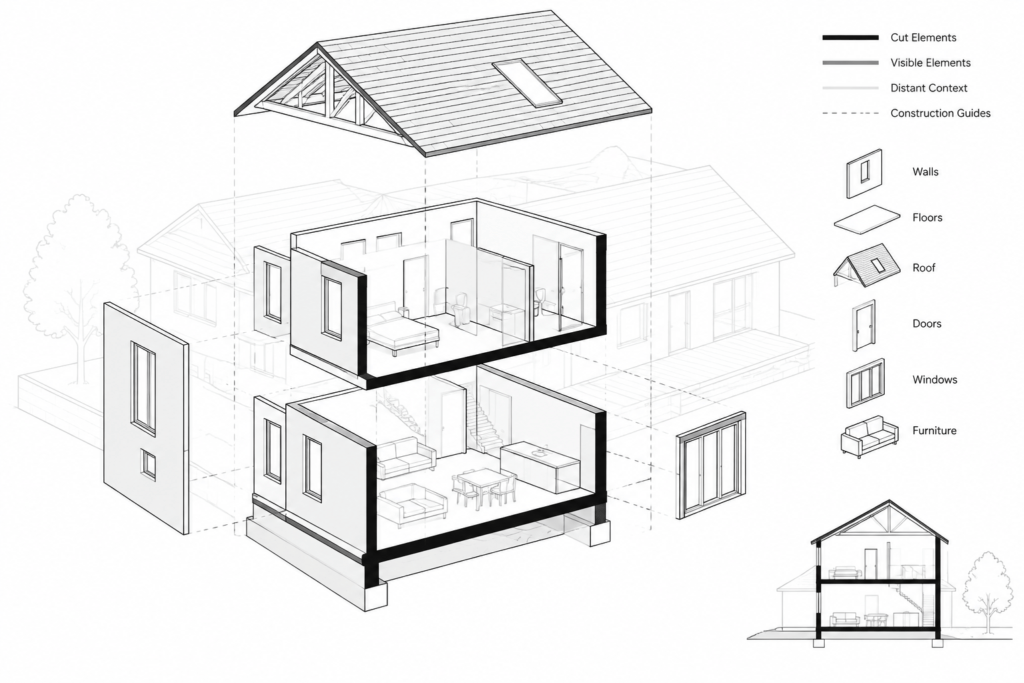
Add visible elements beyond the cut plane
After the cut geometry is established, draw the objects visible behind it. These might include a distant wall, another stair flight, interior doors, windows, cabinets, fixtures, railings, or exterior grade.
Depth should be legible. Objects at the cut plane normally receive the strongest graphic emphasis. Elements immediately beyond the cut are lighter, while distant elements are lighter still or selectively omitted. This visual hierarchy allows the reader to understand the section without confusing background information with cut construction.
| Section content | Graphic role | Typical treatment |
|---|---|---|
| Elements cut by the section plane | Defines the primary construction and spatial boundary | Strong linework and selective poche or material hatch |
| Elements visible beyond | Explains room features and adjacent construction | Medium or light linework |
| Distant context | Provides orientation without dominating the view | Light, simplified linework |
| Construction and projection guides | Supports drafting and coordination | Nonplotting or hidden before issue |
Resolve floors, roofs, and wall intersections
Sections frequently expose inconsistencies that remain hidden in plan. Review each intersection instead of allowing lines to overlap without explanation. Determine how walls meet floor assemblies, where roofs bear or change slope, and how ceilings relate to beams, soffits, or services.
At an early design stage, a simplified assembly may be appropriate. At a later stage, the section may need to show separate layers or refer to enlarged details. Do not add decorative complexity that implies a resolved construction assembly when the design has not been verified.
Coordinate doors and windows vertically
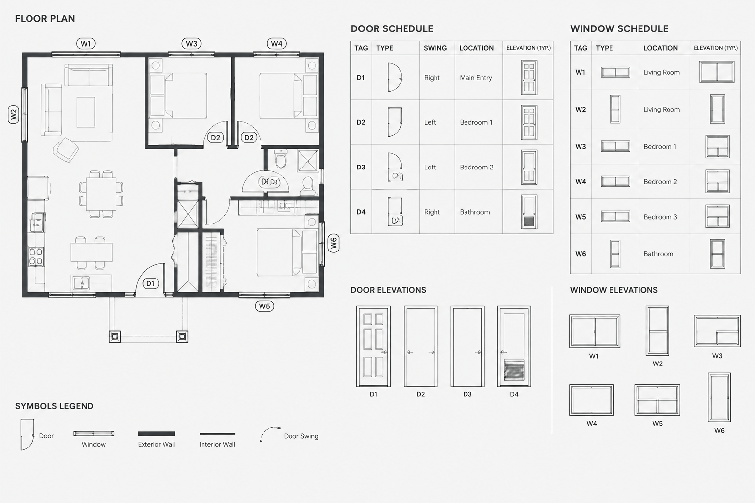
Project the horizontal position of each opening from the plan, then coordinate its vertical position with elevations, schedules, and design information. Verify sill locations, head alignment, transoms, frame relationships, and nearby floor or ceiling changes.
A common drafting error is to insert a generic window or door elevation into the section without checking whether it matches the plan opening. The plan, section, elevation, and schedule should describe the same element. If one view changes, review all related views rather than correcting only the drawing where the conflict was discovered.
Draw stairs as coordinated geometry
Stairs require special attention because the section cut may pass through one flight while showing another flight beyond. Start with known floor and landing levels, establish the run direction, and coordinate the riser and tread layout with the plan. Then distinguish cut stair components from those seen in elevation.
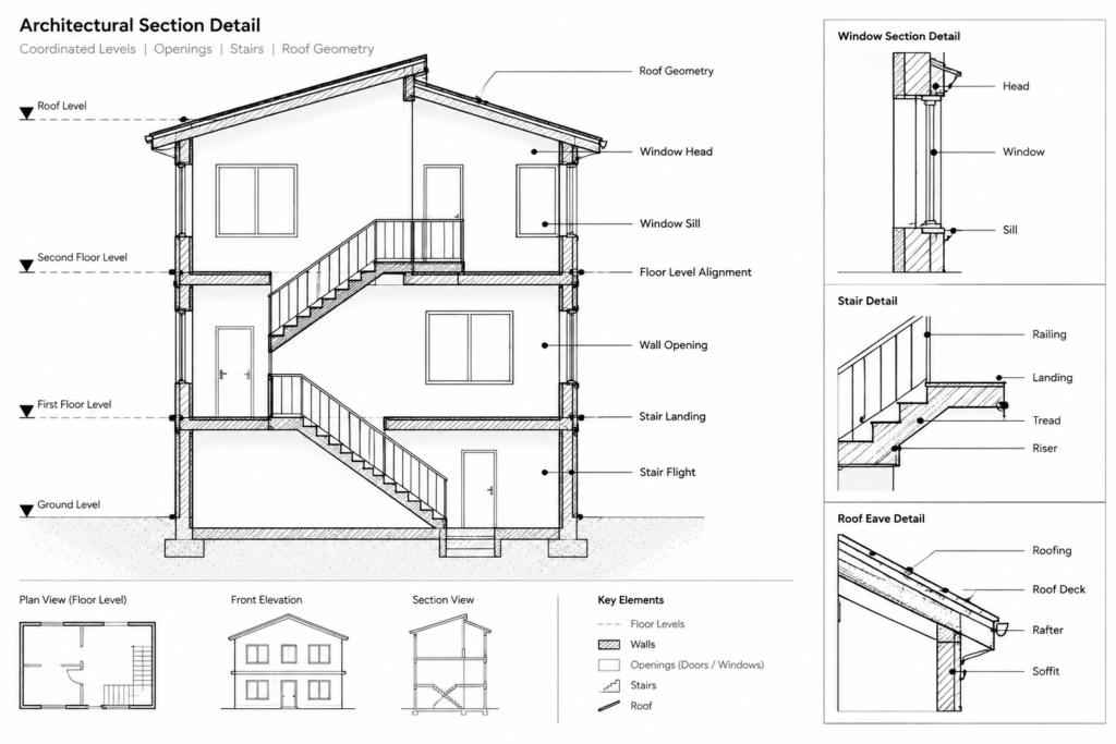
Railings, guards, headroom, landings, and clearances must be evaluated against the applicable project requirements and governing rules. A clean CAD representation does not establish compliance by itself.
Apply hatches and poche selectively
Hatching can distinguish materials and emphasize cut assemblies, but dense patterns may reduce readability or create plotting problems. Use consistent patterns and scales according to the office standard and intended sheet scale. Avoid hatching objects visible beyond the cut unless the graphic convention specifically calls for it.
Solid or dark poche can make cut walls and floors immediately legible. However, it should not cover important joints, openings, edges, or annotation. Test the result at the final plotted size rather than judging it only while zoomed in on screen.
Add annotation after the geometry is stable
Once the section is coordinated, add the information needed to interpret it. Depending on drawing scope, this may include:
- Level and elevation markers
- Room or space names
- Material notes and assembly references
- Door and window identifiers
- Detail callouts
- Key dimensions
- Grid lines or structural references
- Drawing title and section identifier
Dimensions should explain important vertical relationships without repeating every measurable distance. Keep notes close to the objects they describe, use consistent leaders, and avoid crossing dimension strings through dense geometry.
Run a final coordination check
Compare the completed section with every source view. Check wall positions against plans, roof forms against elevations, opening identifiers against schedules, and detail callouts against their destination drawings. Confirm that visible objects are on the correct side of the cut and that hidden objects have not been shown accidentally.
Finally, inspect the section in the intended sheet viewport and produce a test plot or PDF. Review lineweight hierarchy, hatch density, text size, clipped references, missing fonts, and overlapping annotation. A section is complete only when it communicates clearly at publication size and remains coordinated with the rest of the drawing set.