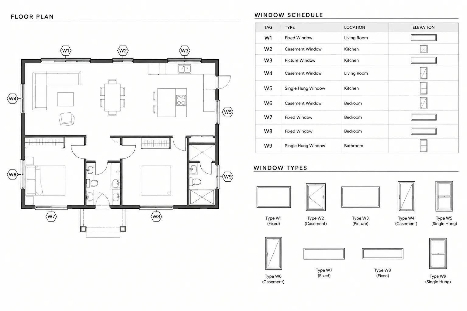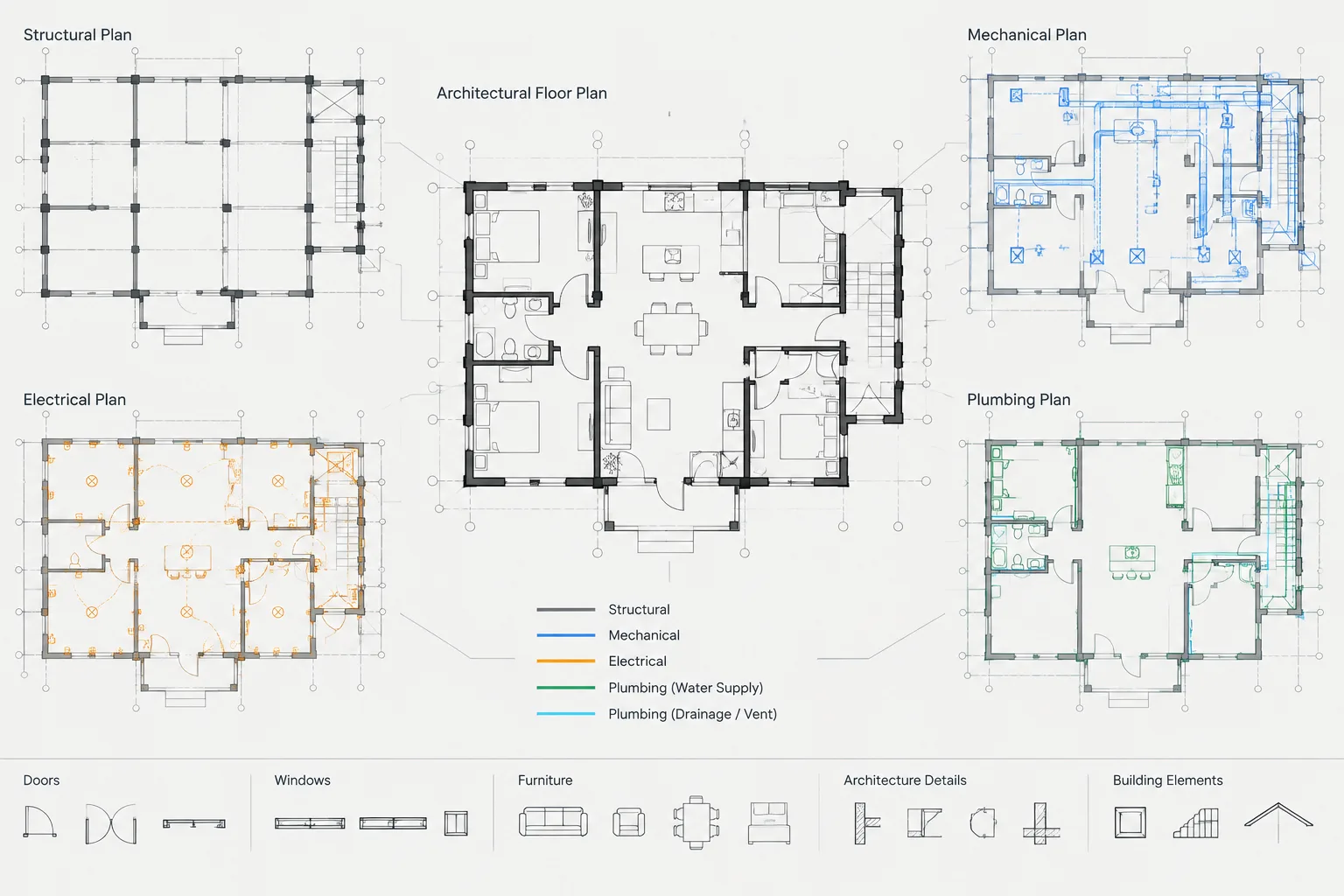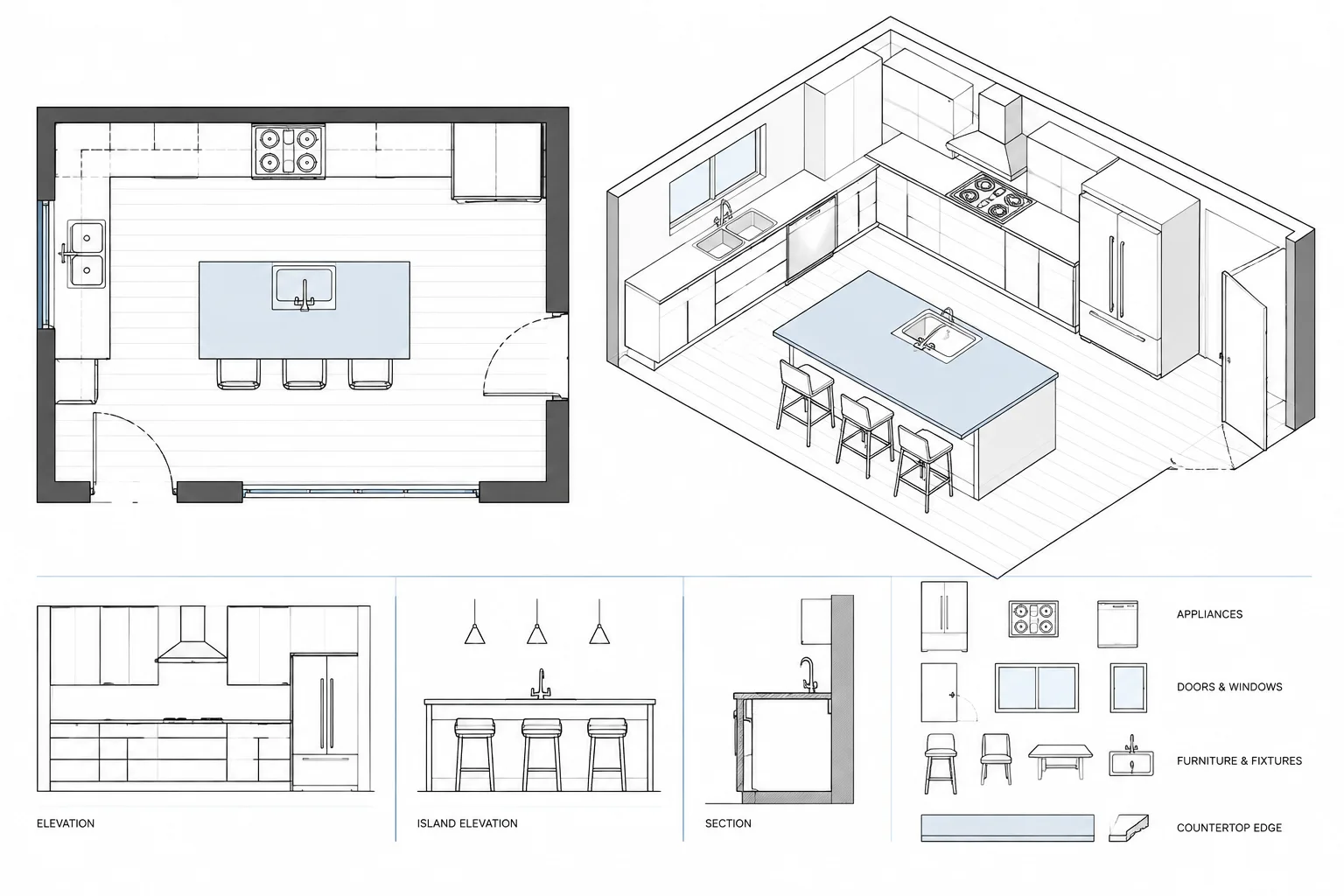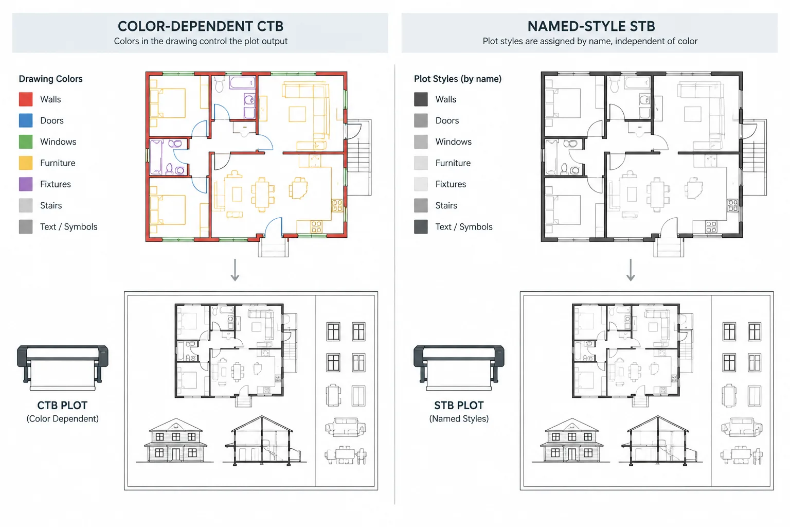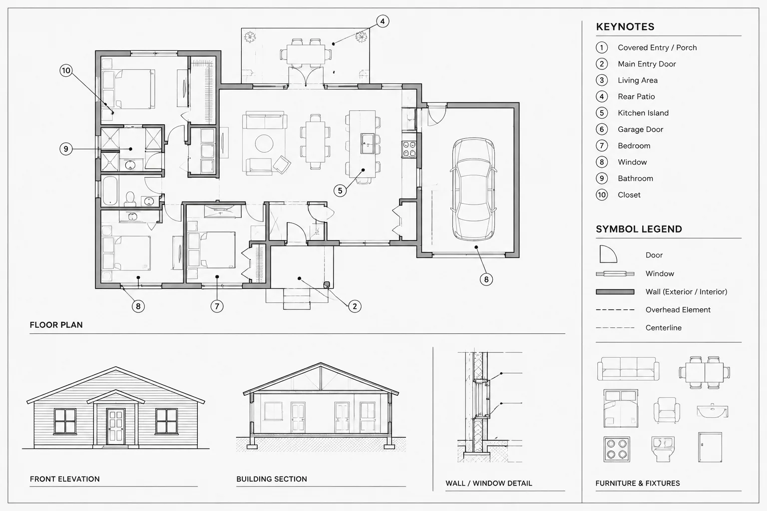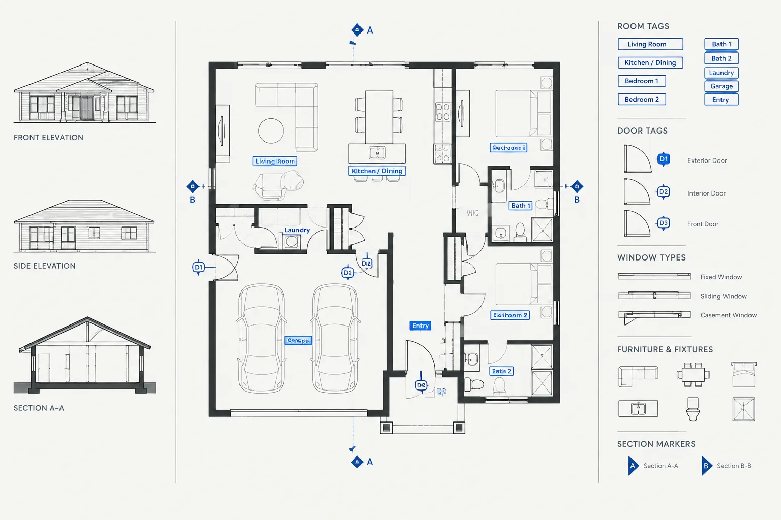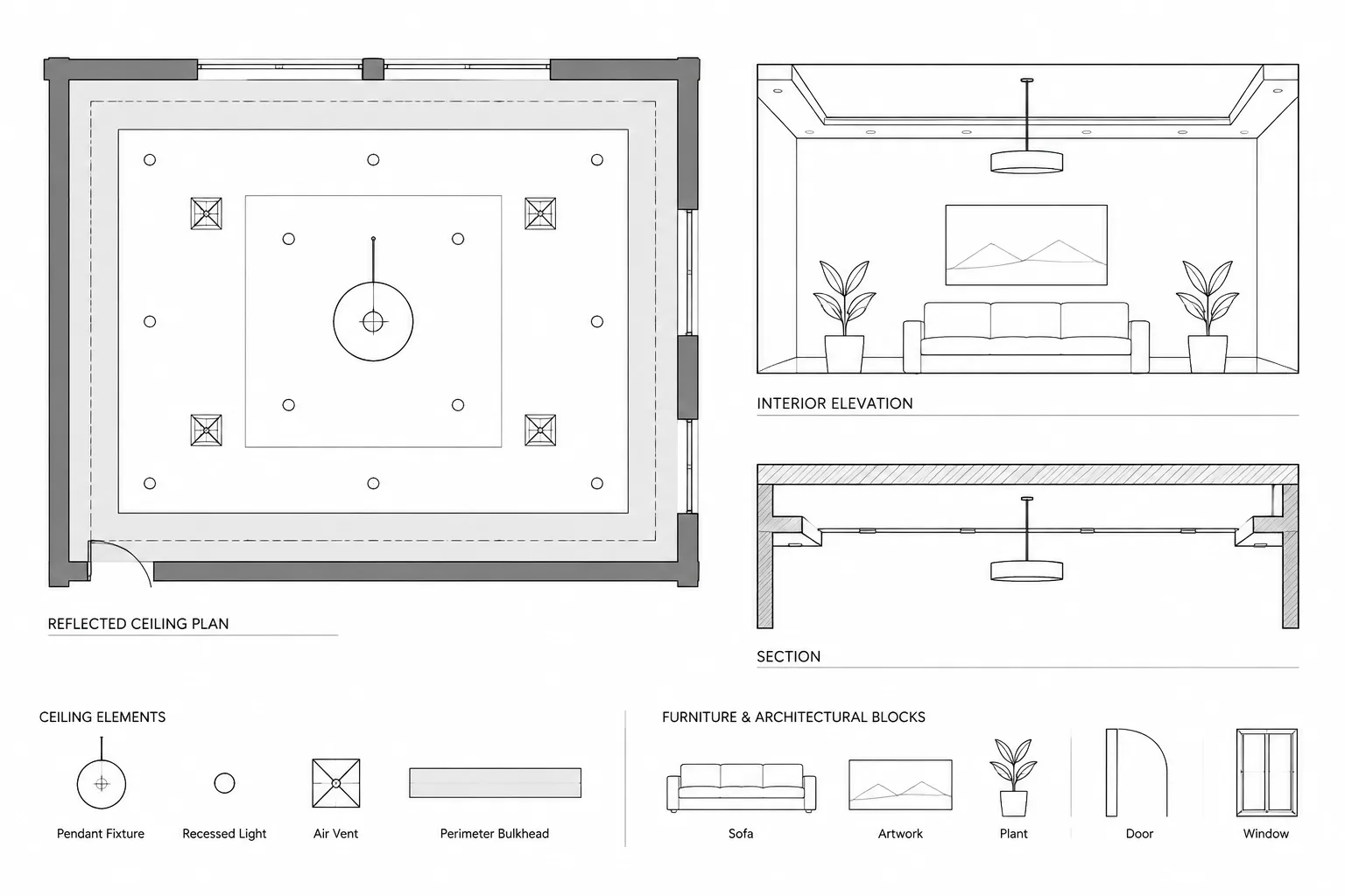
Ceiling bulkheads and soffits connect architectural design intent with ceiling systems, finishes, lighting, building services, and concealed construction. Drafting them clearly requires more than adding an outline to a reflected ceiling plan. Their limits, underside elevations, visible faces, and hidden volume must remain coordinated wherever the condition appears.
This guide explains a view-by-view CAD workflow for establishing dependable geometry, controlling drawing graphics, checking multidisciplinary conflicts, and managing revisions without allowing related plans, elevations, sections, and details to drift apart.
Ceiling bulkheads and soffits often begin as simple design gestures, but they quickly become coordination zones. A lowered ceiling may conceal ductwork, frame a room, align with casework, carry lighting, or create a transition between ceiling systems. If its limits and elevations are not coordinated across the drawing set, the result can be conflicting plans, incomplete sections, and uncertain construction intent.
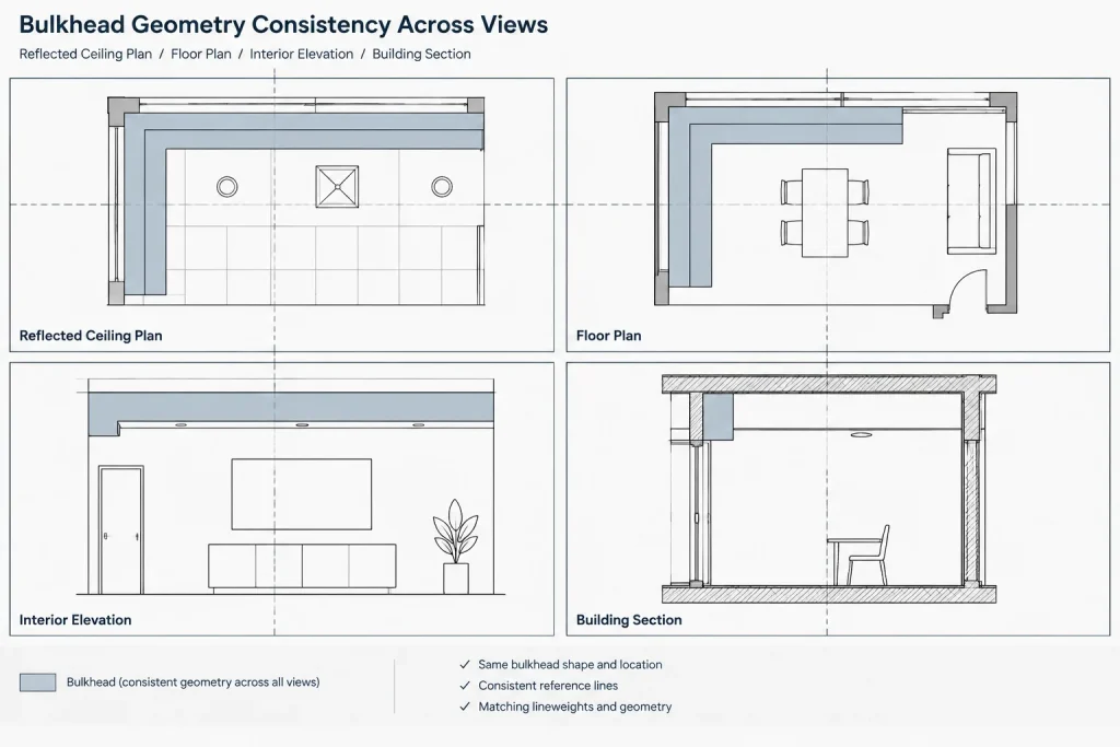
A reliable CAD workflow treats each bulkhead as a three-dimensional condition represented in several related views. Its horizontal footprint appears in plan, its underside appears in the reflected ceiling plan, and its vertical profile must be confirmed in elevations, sections, and details. The objective is not to repeat every line everywhere. It is to make each view communicate the part of the condition that matters in that view.
Understand the condition before drafting it
The terms bulkhead and soffit are sometimes used interchangeably in project conversations, but they can describe different conditions. A soffit generally refers to an exposed underside, while a bulkhead commonly describes a lowered or boxed-out construction volume. Office terminology varies, so drawing notes and labels should identify the actual construction intent rather than relying on terminology alone.
Before drawing, determine why the element exists. Common purposes include:
- Concealing ducts, pipes, structure, tracks, or other overhead components
- Creating a ceiling transition between adjacent spaces
- Aligning with partitions, columns, casework, or architectural features
- Providing a location for lighting, diffusers, speakers, sprinklers, or access panels
- Defining a perimeter, corridor edge, reception zone, or feature area
- Forming a pocket for a curtain, shade, screen, or movable component
This purpose affects what must be coordinated. A decorative ceiling drop may be governed mainly by visual alignment, while a service enclosure depends on verified space for equipment, supports, access, and installation tolerances.
Establish a dependable plan footprint
Begin with a clear horizontal outline representing the bulkhead or soffit limits. Where practical, use continuous, closed geometry rather than unrelated line segments. A controlled outline is easier to revise, hatch, compare, and reuse in related views.
Anchor the footprint to stable building geometry. Appropriate references may include wall faces, column grids, room centerlines, casework faces, or established ceiling control lines. Avoid locating a bulkhead from temporary furniture or loosely placed annotation unless that relationship is intentional.
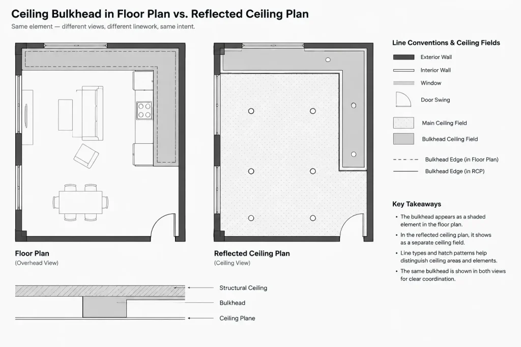
Ask the following questions while developing the footprint:
- Does the edge align with a wall face, opening, cabinet, or other visible feature?
- Does the bulkhead continue through adjacent rooms or stop at a partition?
- Are inside and outside corners constructible and graphically clear?
- Will the shape conflict with doors, tall equipment, curtains, or operable partitions?
- Is the outline based on a finished face, framing limit, or design centerline?
The chosen reference should remain consistent. Mixing finished-face and framing references without explanation can cause offsets between plans and details.
Show the right information in each drawing
Floor plan
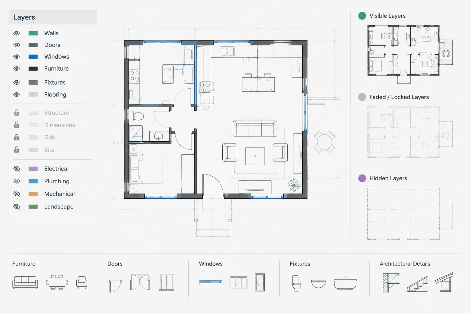
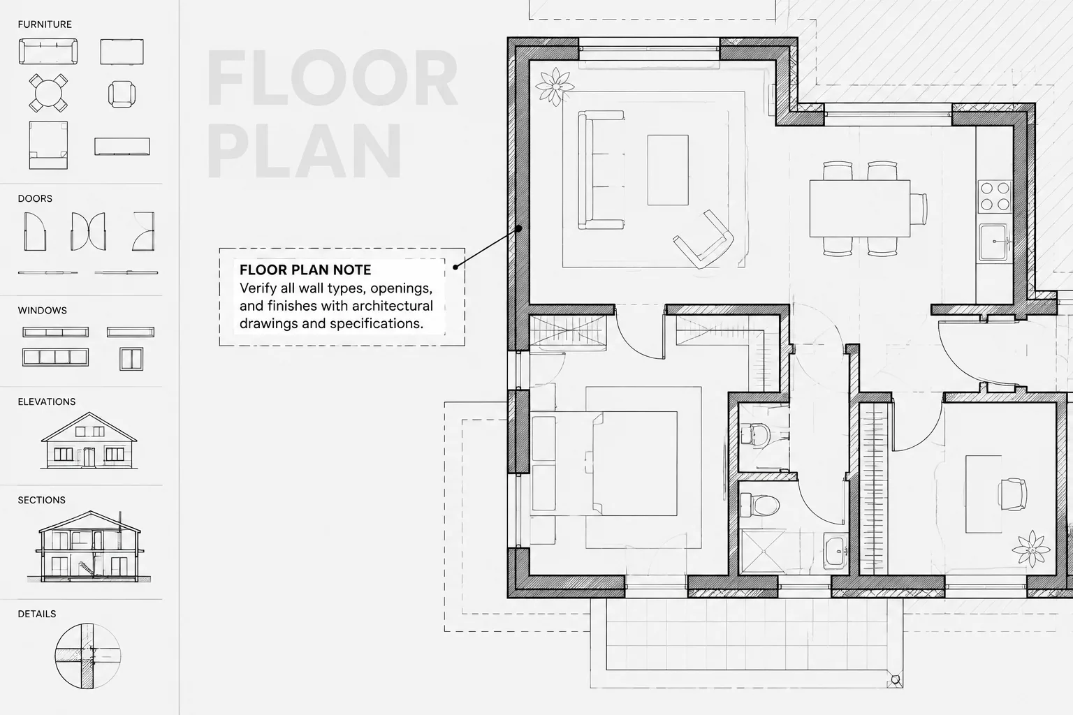
In a floor plan, an overhead bulkhead may be shown with an overhead or hidden-line convention when it affects spatial understanding, clearances, openings, casework, or other plan elements. Do not automatically show every ceiling feature on every floor plan. Excess overhead information can compete with walls, doors, room tags, and dimensions.
If the bulkhead is already fully described in the reflected ceiling plan, the floor plan may need only a limited indication or a reference to another view. Use a consistent project convention so readers can distinguish overhead construction from floor-level geometry.
Reflected ceiling plan
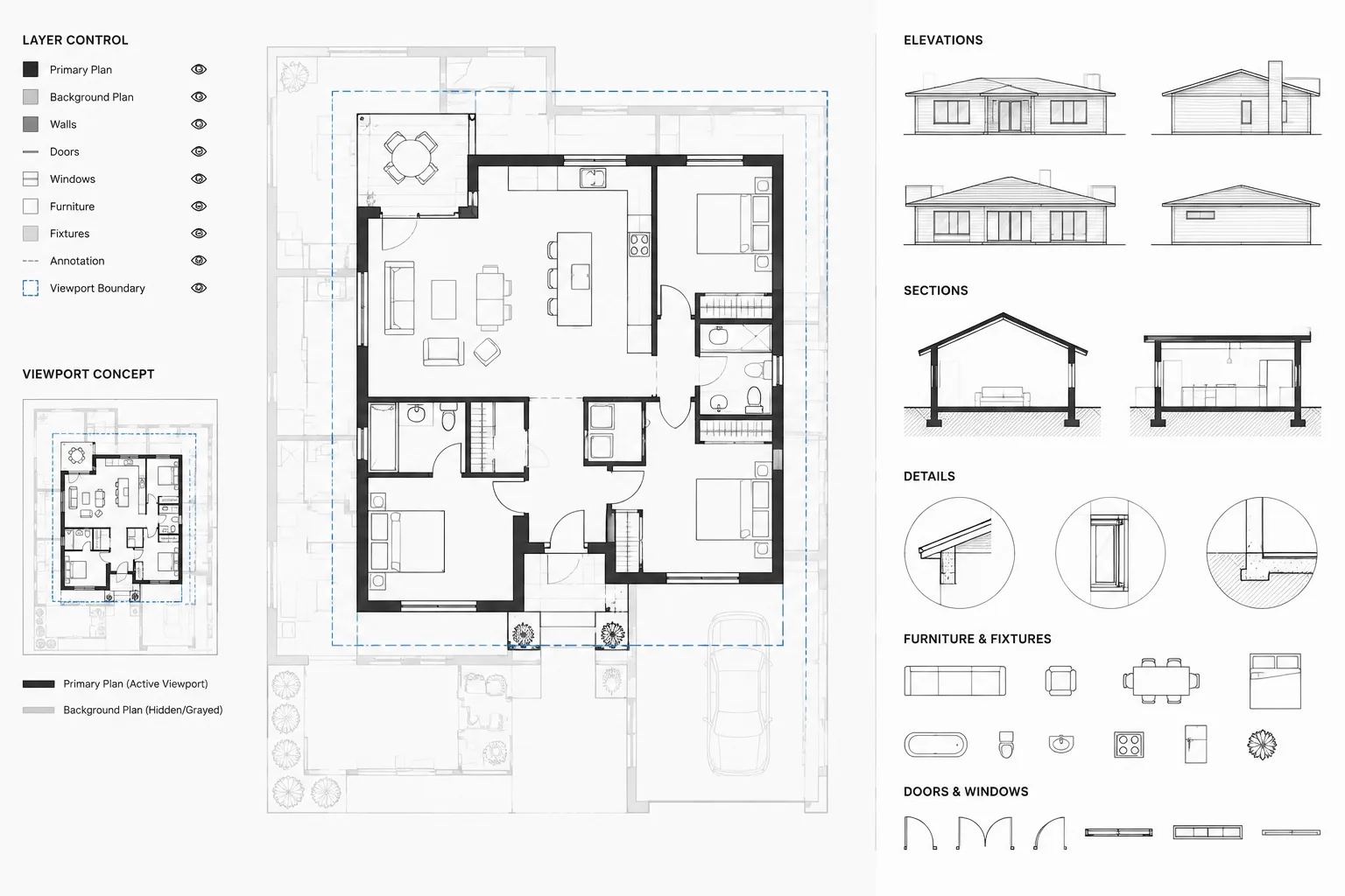
The reflected ceiling plan is usually the primary location for the bulkhead footprint and underside configuration. It should make the boundaries between ceiling fields understandable and show how the condition relates to fixtures and devices.
Coordinate the bulkhead with:
- Ceiling material or system boundaries
- Ceiling height tags and level changes
- Light fixtures and linear lighting
- Air devices and return-air components
- Sprinklers, detectors, speakers, sensors, and cameras
- Access panels and maintenance zones
- Ceiling grids, joints, reveals, and trim lines
A ceiling height tag should clearly apply to the intended surface. When several elevations occur close together, use leaders, separated tags, or a section reference rather than leaving the reader to guess which plane a tag describes.
Interior elevations
Interior elevations explain the visual effect of the bulkhead. Show its vertical face, underside, relationship to doors and casework, and alignment with finish joints or architectural features. Elevations are particularly important where a ceiling drop frames a wall composition or continues above built-in work.
Dimensions should communicate design control rather than restating every plan measurement. Useful controls may include the underside elevation, the relationship to adjacent openings, and the alignment of visible edges.
Sections and details
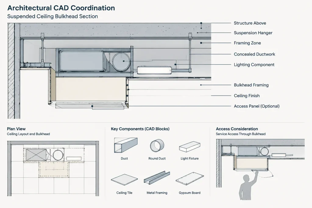
A section verifies whether the volume implied in plan can actually contain the intended systems. Show enough surrounding context to explain the relationship among structure, framing, ceiling finishes, services, and adjacent construction.
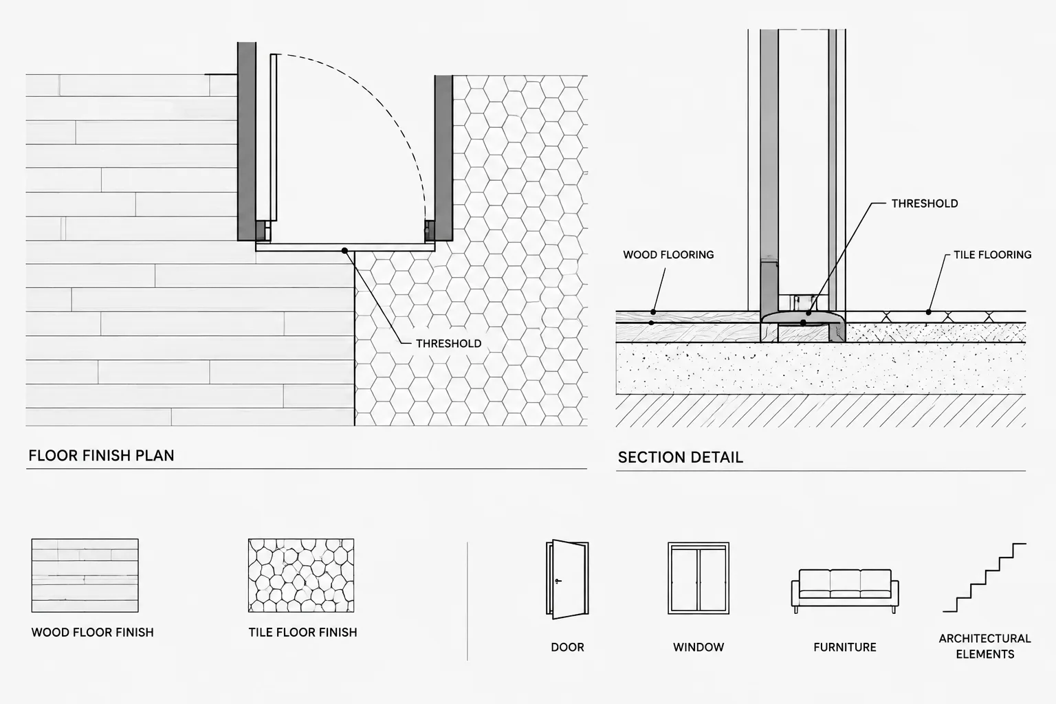
A larger-scale detail may be necessary where the condition includes reveals, light coves, access panels, curtain pockets, finish transitions, or unusual support. Do not imply a fully resolved assembly with a generic outline if its support, attachment, movement, or access requirements remain unknown.
Use a coordinated layer and property strategy
Bulkhead geometry should be separable from unrelated ceiling and partition geometry. The exact layer names depend on the office standard, but the layer structure should support visibility control, plotting, and consultant coordination.
A practical division may distinguish among:
| Information type | Coordination purpose |
|---|---|
| Primary bulkhead outline | Defines visible limits in ceiling plans or elevations |
| Overhead representation | Shows the condition in floor plans without reading as cut geometry |
| Ceiling height annotation | Identifies separate underside and adjacent ceiling planes |
| Finish or material pattern | Differentiates ceiling fields when needed |
| Reference or clearance geometry | Supports coordination without plotting as finished work |
Keep object properties controlled through the agreed layer or block strategy. Random color, linetype, and lineweight overrides make it harder to adjust graphics consistently across multiple sheets.
Coordinate the bulkhead as a volume
A common drafting error is to coordinate only the visible underside. The construction also occupies space above that surface. Consider the full volume from the finished face to the structure or support above, including framing depth and space needed by concealed systems.
Overlay or reference current consultant backgrounds where available. Compare the architectural enclosure against structural depth, duct routes, piping, equipment, and required access. A clean-looking reflected ceiling plan does not prove that the concealed zone is feasible.
When a conflict is discovered, record the design decision rather than shifting lines in only one view. A change in bulkhead width or elevation may affect the floor plan, ceiling plan, elevations, lighting layout, finish boundaries, and details.
Manage repeated and irregular conditions carefully
Repeated bulkheads can be managed with blocks or referenced geometry when the conditions are genuinely identical. Reuse is useful for consistency, but it should not hide local differences. End conditions, wall thicknesses, room widths, device locations, and service routes may vary.
For irregular shapes, use a clearly controlled boundary and verify that arcs, angled segments, and offsets remain connected after revisions. Complicated geometry can generate small gaps or overlapping segments that are difficult to see at sheet scale. Inspect corners closely and test any hatch or boundary-dependent annotation before issue.
Common coordination failures
- Mismatched footprints: The floor plan, reflected ceiling plan, and elevation show different limits.
- Ambiguous height tags: A tag is placed near several ceiling planes without a clear association.
- Unverified service space: The visible enclosure is drawn before concealed equipment and access needs are understood.
- Broken alignments: A bulkhead nearly aligns with a door, cabinet, or wall feature but misses it without design intent.
- Excessive floor-plan graphics: Overhead lines obscure primary plan information.
- Unsupported detail assumptions: A section suggests framing or attachment that has not been verified.
- Partial revision: One view changes while related elevations, tags, or details remain outdated.
Quality-control checklist
Before issuing drawings, review each bulkhead and soffit condition across the full set:
- Confirm that plan outlines match the associated elevations and sections.
- Verify that every ceiling elevation applies to an identifiable surface.
- Check alignments with walls, openings, casework, and finish joints.
- Review current structural and building-service backgrounds.
- Confirm that lights, air devices, sprinklers, and access panels are intentionally located.
- Check that floor-plan overhead lines use the project drafting convention.
- Inspect corners, offsets, hatches, and closed boundaries for drafting errors.
- Verify that section and detail references point to the current views.
- Plot or preview the sheets at their intended output scale to test clarity.
- Flag unresolved support, access, code, or product requirements for project-specific verification.
Draft the relationship, not just the outline
A well-coordinated bulkhead is more than a rectangle on a ceiling plan. It is a volume that affects room composition, concealed services, fixtures, finishes, and construction details. The most dependable workflow establishes one controlled footprint, represents it appropriately in each view, and verifies every change across the related drawings.
CAD geometry can communicate the design clearly, but it cannot establish whether a proposed assembly satisfies project requirements by itself. Final dimensions, access provisions, supports, system clearances, product requirements, and applicable regulations must be confirmed for the actual project.
A practical change-control method
Bulkhead coordination becomes easier when the drawing team identifies a controlled geometric reference rather than redrawing the condition independently in every view. The reference may be the finished-face footprint, a ceiling control line, or another clearly documented project datum. Related views can then be checked against that agreed design basis.
Record what controls the condition
Before revising a bulkhead, identify the reason for its current location and profile. A line may be controlled by casework, an opening, a ceiling field, concealed services, or a visual alignment. Moving it without understanding that relationship can solve a conflict in one drawing while creating another elsewhere.
- Geometry control: Identify the boundary or alignment that governs the footprint.
- Vertical control: Confirm which underside and adjacent ceiling planes apply.
- Coordination control: Note the concealed system, fixture, finish, or architectural feature affecting the design.
- View impact: List the plans, elevations, sections, details, tags, and references that require review.
Separate confirmed work from coordination graphics
Reference lines, clearance zones, consultant backgrounds, and design-study geometry should not read as finished construction. Keep them visually and organizationally distinct from architectural linework intended for issue. This makes unresolved conditions easier to identify and reduces the chance that temporary coordination graphics will be mistaken for final scope.
Review revisions by relationship
After changing a footprint or elevation, review the connected relationships rather than checking only the edited object. Confirm the edge against walls and casework, the underside against fixtures and services, and the vertical face against openings and finish alignments. The revision is complete only when the affected views communicate the same condition.
Final documentation perspective
A bulkhead drawing should communicate where the construction begins and ends, which surface is being identified, and where additional information can be found. It should also make unresolved requirements visible to the project team rather than concealing uncertainty behind overly specific generic details.
Drawing consistency is a coordination aid, not a substitute for project review. Construction assemblies, support methods, access needs, system clearances, product requirements, and regulatory criteria must be verified by the responsible project professionals.
Frequently asked questions
Should a ceiling bulkhead appear on both the floor plan and reflected ceiling plan?
Show it in each view only when it contributes useful information. The reflected ceiling plan normally explains the underside and ceiling relationships, while a floor plan may use an overhead convention when the condition affects openings, casework, clearances, or spatial interpretation.
What is the most important reference for drafting a bulkhead footprint?
Use stable project geometry tied to the design intent, such as wall faces, grids, casework faces, or established ceiling control lines. Clearly distinguish whether the outline represents a finished face, framing limit, or another reference.
How should ceiling height tags be handled near several soffit levels?
Each tag should have an unmistakable relationship to the surface it describes. Leaders, separated annotation, and section references can clarify closely spaced ceiling planes.
Can repeated soffits be created as CAD blocks?
Reusable geometry can improve consistency when the conditions are genuinely the same. Each instance still requires review for local wall conditions, end treatments, fixtures, service routes, and adjacent finishes.
Why is a section necessary if the reflected ceiling plan is complete?
The ceiling plan explains the horizontal arrangement but does not fully verify the concealed volume. A section can reveal relationships among the underside, framing, structure, services, finishes, and access requirements.
How can drawing teams prevent mismatched bulkhead revisions?
Document the controlling geometry and review every affected view after a change. Plans, ceiling plans, elevations, sections, details, height tags, fixture layouts, finish boundaries, and view references may all require coordination.