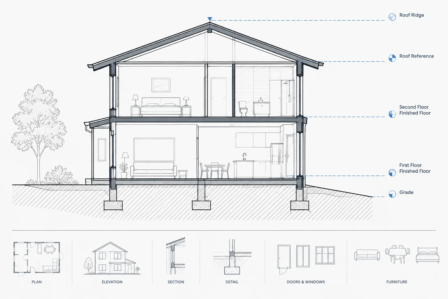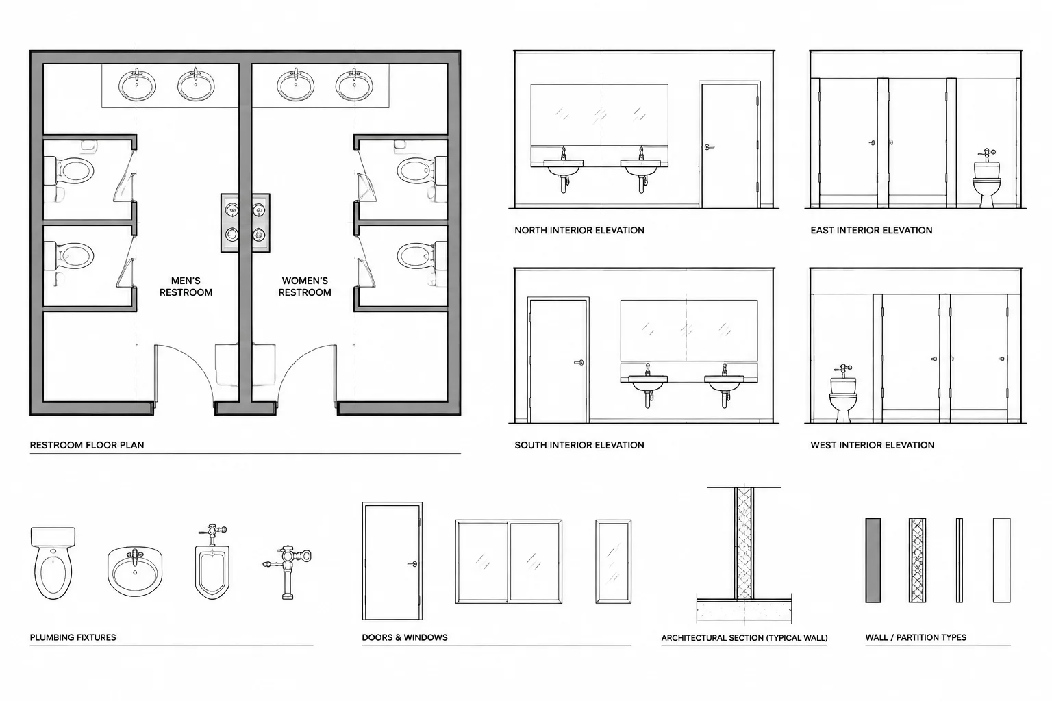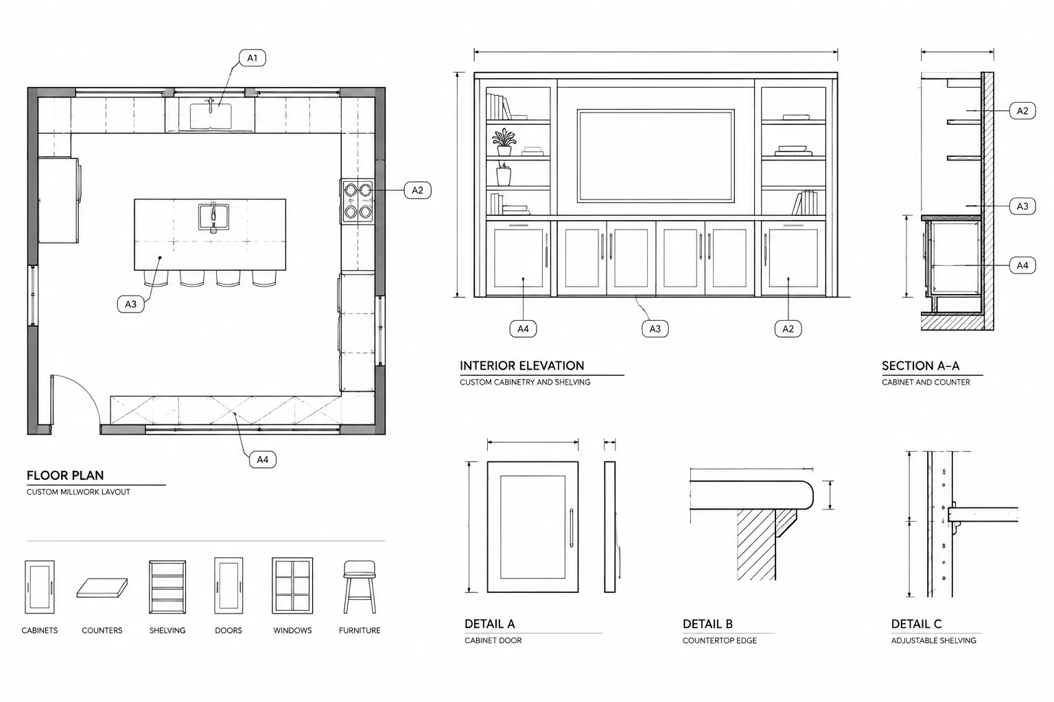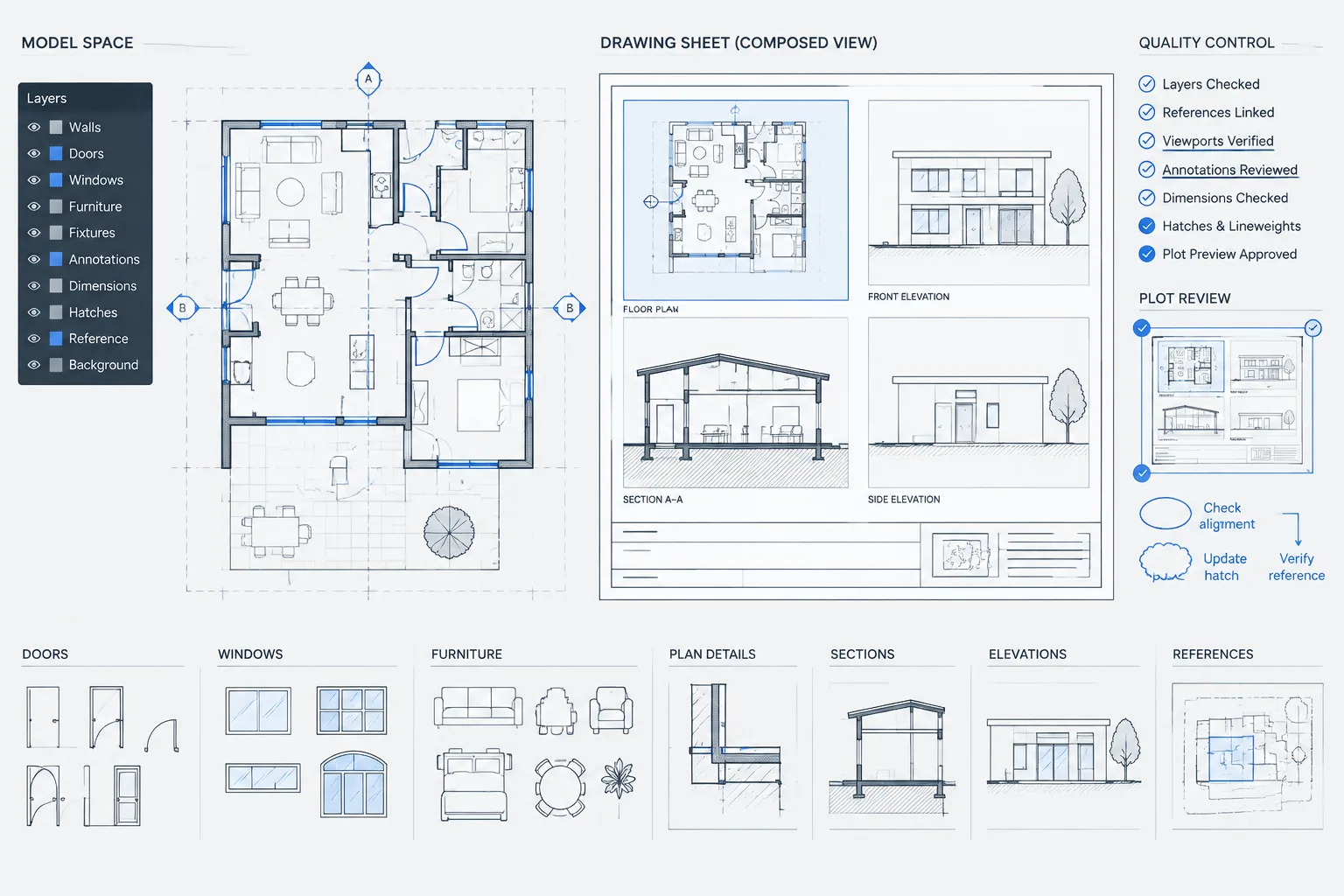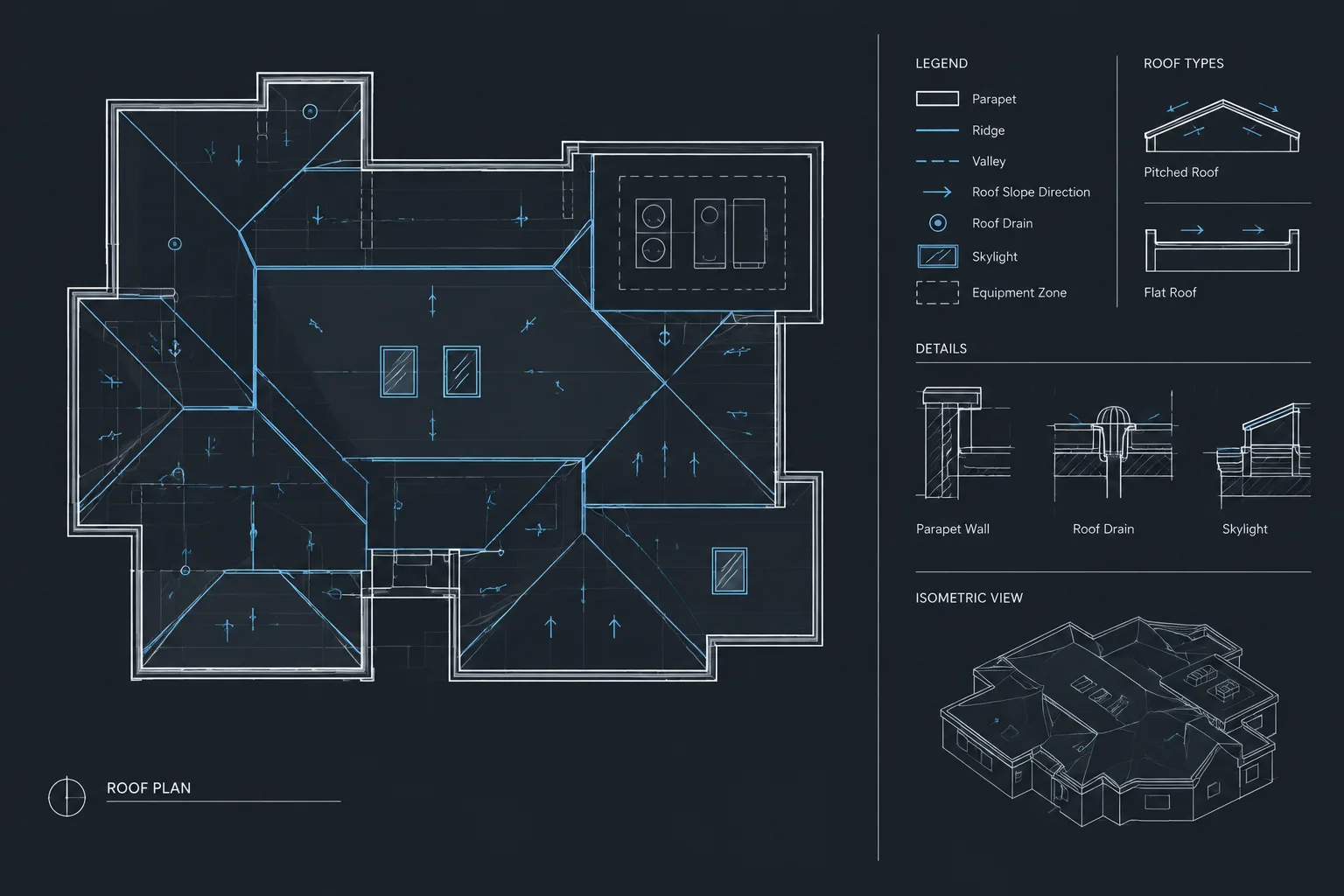
An architectural roof plan communicates the roof’s overall geometry and its relationship to the building below. It may show roof edges, parapets, ridges, hips, valleys, slopes, drainage elements, openings, equipment zones, and references to related details. Although it is drawn as a plan view, it must coordinate closely with floor plans, exterior elevations, building sections, structural information, and consultant drawings.
A reliable roof plan should do more than outline the top of the building. It should make the intended roof form understandable, identify important transitions, and provide a stable base for coordination. The following workflow focuses on organizing and drafting an architectural roof plan in CAD without assuming project-specific dimensions, materials, or code requirements.
Define the purpose of the roof plan first
Before drafting, determine what the roof plan is expected to communicate. A small sloped roof may need geometry, slope direction, roof edges, penetrations, and detail references. A larger low-slope roof may require parapets, drains, overflow provisions, expansion joints, equipment areas, access points, and multiple elevation references.
The architectural roof plan is not automatically a structural framing plan, a roofing shop drawing, or a complete drainage design. Those documents may contain different information and may be prepared by other disciplines. Clearly defining the architectural scope helps prevent duplicate or conflicting graphics.
Start with coordinated building geometry
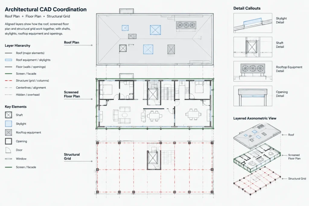
Use the current floor plan, structural grid, or another controlled project base rather than redrawing the building footprint from memory. In a multi-file workflow, attach the relevant plans as external references. If the project is maintained in a single file, use disciplined layers and avoid copying uncontrolled versions of the footprint.
Confirm the following before developing the roof:
- The exterior wall and parapet locations match the current plans.
- Major shafts, stairs, elevators, and vertical service zones are represented.
- Courtyards, canopies, setbacks, and changes in building height are included.
- The structural grid or other primary reference system aligns across drawings.
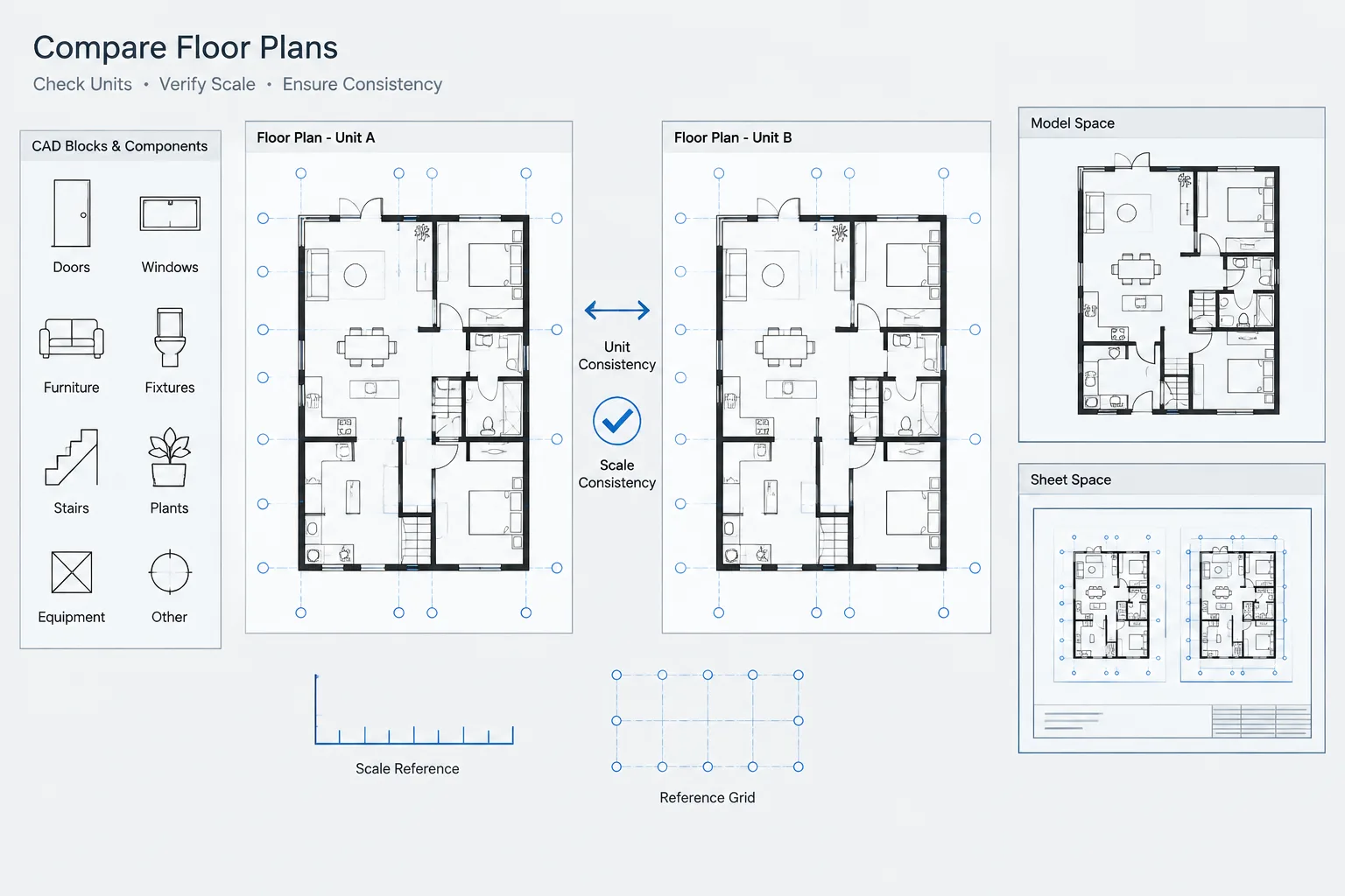
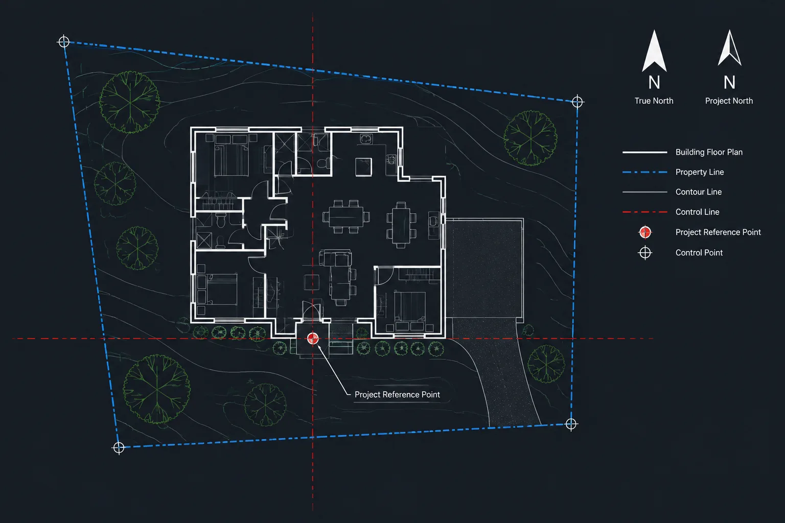
- The project origin, rotation, and drawing units match the rest of the CAD set.
Keep the plan below visually subordinate. A screened or muted underlay can provide context without competing with the roof graphics.
Construct the roof boundary
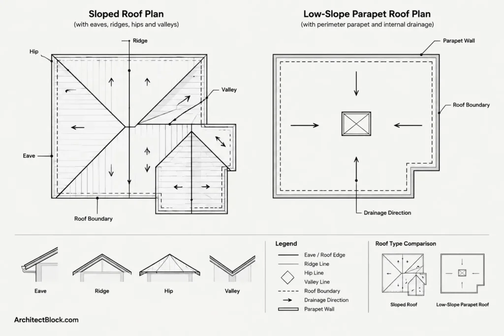
Draft the primary roof perimeter from the controlling building geometry. The visible roof edge may align with an exterior wall, extend beyond it as an overhang, or be contained by a parapet. Do not assume that the floor-plan wall outline is also the roof outline.
Closed polylines are useful for managing roof areas, checking boundaries, and applying hatches. However, separate boundaries may be needed where the roof changes elevation, material, or drainage behavior. Avoid forcing several distinct roof zones into one complicated object if simpler components will be easier to edit and review.
Sloped roof geometry
For sloped roofs, establish the eaves or outer edges before locating ridges, hips, and valleys. The geometry should be based on the intended roof form and verified against sections and elevations. Intersecting roof masses can create valleys or other transitions that are not obvious from the floor plan alone.
Show each important line according to what it represents:
- Ridge: the high line where sloping roof surfaces meet.
- Hip: an outward-sloping intersection between roof planes.
- Valley: an inward intersection that commonly collects water.
- Eave: the lower edge of a sloped roof, often extending beyond the wall.
- Cricket or saddle: a localized roof form used to redirect water around an obstruction.
Use slope arrows or another consistent project convention to clarify the direction of fall. Pair them with appropriate slope information when that information has been verified for the project.
Low-slope and parapet roofs
A low-slope roof plan is often organized around drainage areas rather than prominent ridges and eaves. Begin with parapets, roof boundaries, changes in elevation, and major obstructions. Then establish drainage directions and the relationship among roof drains, scuppers, gutters, or other project-specific elements.
Do not treat drainage arrows as decoration. They should describe a plausible path that responds to high points, low points, roof edges, penetrations, and changes in roof elevation. Final drainage design and required provisions must be verified with the responsible project professionals and applicable requirements.
Add openings, penetrations, and rooftop elements
Once the primary geometry is stable, add elements that interrupt or occupy the roof. These may include skylights, roof hatches, vents, flues, mechanical curbs, screens, solar equipment zones, access paths, and service areas. Use verified equipment information rather than relying on a generic block as the final project definition.
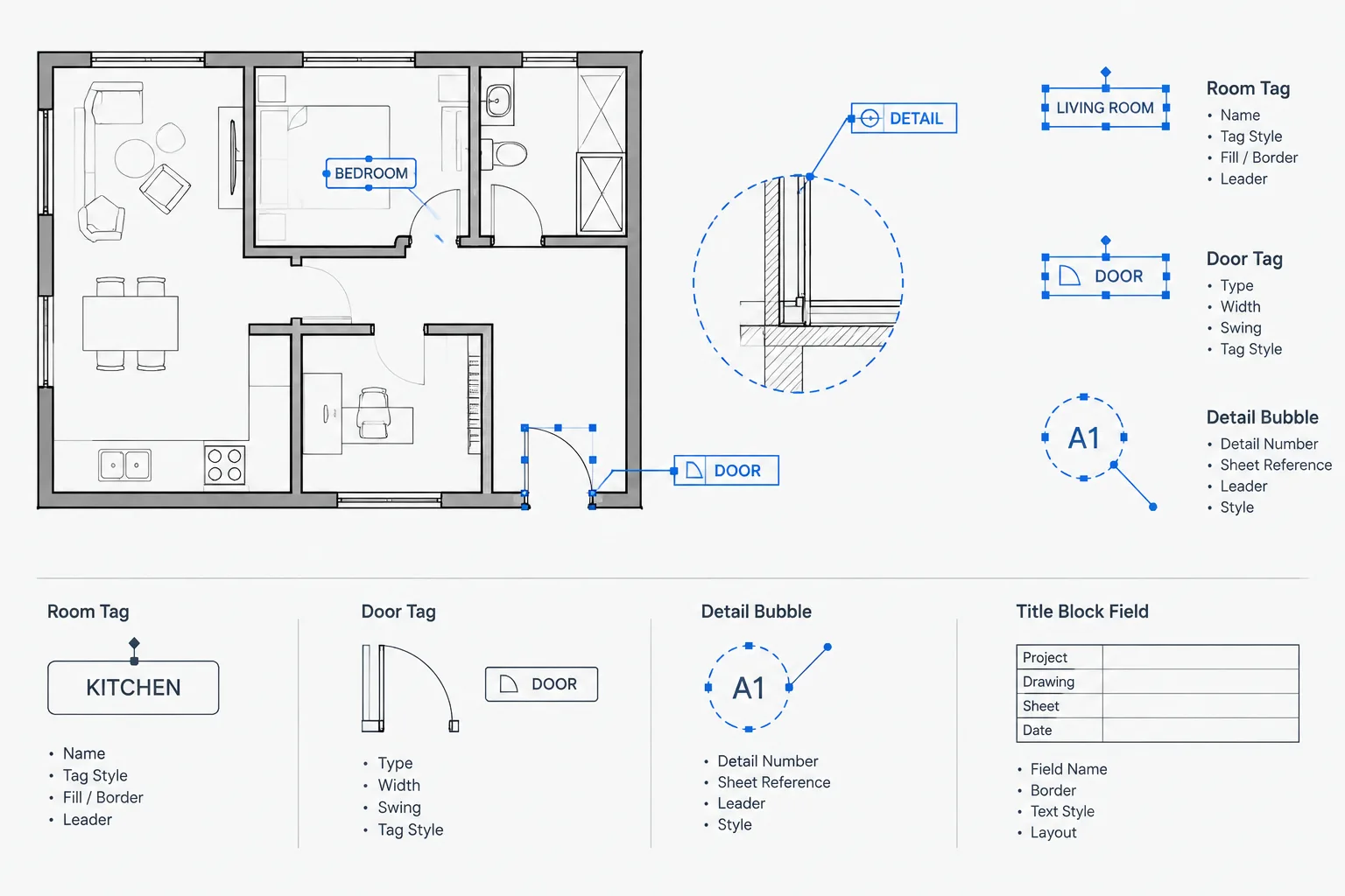
A CAD block can represent a recurring symbol efficiently, but its insertion point, orientation, extents, and attributes should support coordination. Distinguish between a symbolic marker and an accurately sized opening or curb. If exact dimensions are controlled by another discipline or a selected product, identify that dependency in the workflow rather than guessing.
Organize roof plan layers
Layer names should follow the project’s established CAD standard. The goal is to separate information by function so it can be displayed, checked, and plotted predictably.
| Information group | Typical content | Drafting purpose |
|---|---|---|
| Roof outlines | Edges, parapets, overhangs, and separate roof zones | Defines the primary roof form |
| Roof transitions | Ridges, hips, valleys, and elevation changes | Explains relationships between roof planes |
| Drainage | Direction arrows, drains, scuppers, and gutters | Communicates intended water movement |
| Openings and equipment | Hatches, skylights, curbs, screens, and penetrations | Supports architectural and consultant coordination |
| Annotation | Notes, tags, elevations, and detail references | Identifies and explains roof components |
| Reference information | Walls below, grids, and consultant underlays | Provides alignment context |
Keep reference information visually lighter than the active roof work. Hatches should clarify roof zones or materials without hiding slope arrows, tags, or transition lines.
Build a clear graphic hierarchy
The most important roof boundaries and cut-related edges should read first. Secondary lines, such as slope transitions or overhead context, should remain visible without carrying the same visual weight. Annotation and symbols must be legible at the intended sheet scale.
Review the plotted result rather than judging only from a brightly colored model-space display. A clear hierarchy commonly depends on a combination of layer settings, lineweights, linetypes, screening, hatch density, and annotation scale.
Annotate the roof plan for coordination
Roof annotations should help the reader understand geometry and locate related information. Depending on the project, useful annotations may include:
- Roof area or roof-type tags.
- Slope directions and verified slope designations.
- Elevation markers at significant high and low points.
- Labels for drains, scuppers, gutters, and downspout locations.
- Tags for skylights, hatches, screens, and rooftop equipment.
- Section, elevation, and enlarged-detail references.
- Notes identifying work by another discipline when appropriate.
Place annotations close enough to their subjects to be understood, but avoid stacking labels over valleys, drainage paths, or dense equipment areas. Leaders should terminate clearly and should not cross unrelated symbols when a cleaner route is available.
Coordinate the roof with elevations and sections
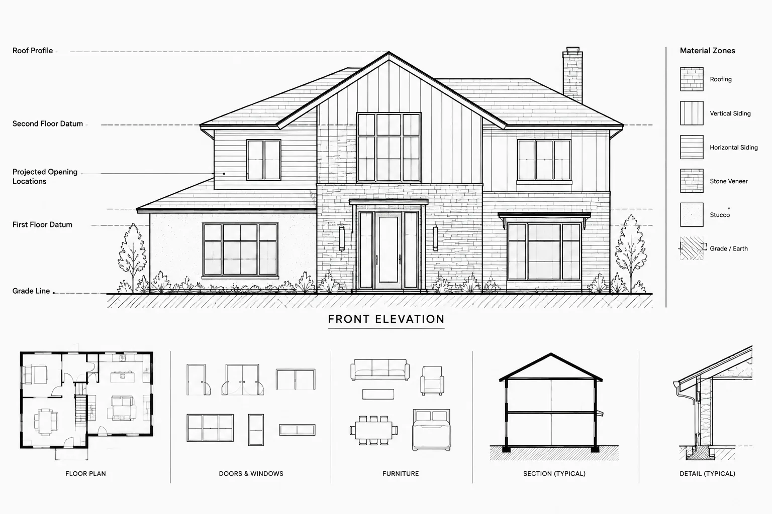
Roof plans, elevations, and sections describe the same building from different viewpoints. A change in one view should trigger a review of the others.
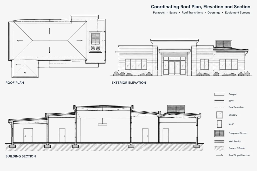
Check that parapet heights, eaves, ridges, overhangs, canopies, roof openings, and equipment screens appear consistently. Sections are especially important where roof planes intersect, where a lower roof meets a taller wall, or where the plan alone cannot explain vertical relationships.
Exterior elevations can reveal inconsistencies that are easy to miss in plan, such as an uneven eave line, a misplaced downspout, or rooftop equipment visible above an intended screen. Use cross-view checking as part of the drafting process rather than postponing it until sheet completion.
Coordinate consultant information without merging responsibilities
Architectural, structural, mechanical, plumbing, and electrical roof information may overlap. Reference current consultant backgrounds and identify conflicts, but avoid silently changing consultant-controlled elements in the architectural file.
Pay particular attention to:
- Openings that affect structural framing.
- Mechanical units, curbs, and required service zones.
- Drain and overflow locations.
- Penetrations near valleys, parapets, or roof transitions.
- Equipment screens and their relationship to elevations.
- Roof access and the clear space around access points.
Record unresolved items through the project’s coordination process. Temporary assumptions should be recognizable and replaced when verified information becomes available.
Complete a roof plan quality check
Before issuing the drawing, perform both a visual review and a CAD cleanup. Trace each roof edge and drainage path methodically instead of scanning the sheet at random.
- Confirm that roof boundaries align with the current building plans.
- Check that ridges, hips, valleys, and slope arrows describe a coherent roof form.
- Verify that roof openings align with shafts, rooms, and consultant information below.
- Compare significant roof elevations with sections and exterior elevations.
- Look for duplicated lines, open boundaries, isolated objects, and obsolete blocks.
- Confirm that notes and tags are readable at the final plotted scale.
- Review xreference paths, layer visibility, hatch behavior, and viewport output.
- Ensure unresolved design or coordination items are not presented as verified information.
A well-coordinated architectural roof plan is built from controlled references, understandable roof geometry, disciplined layers, and repeated checks across the drawing set. Treating it as a coordination drawing—not merely a roof outline—produces a clearer CAD file and makes later revisions easier to manage.