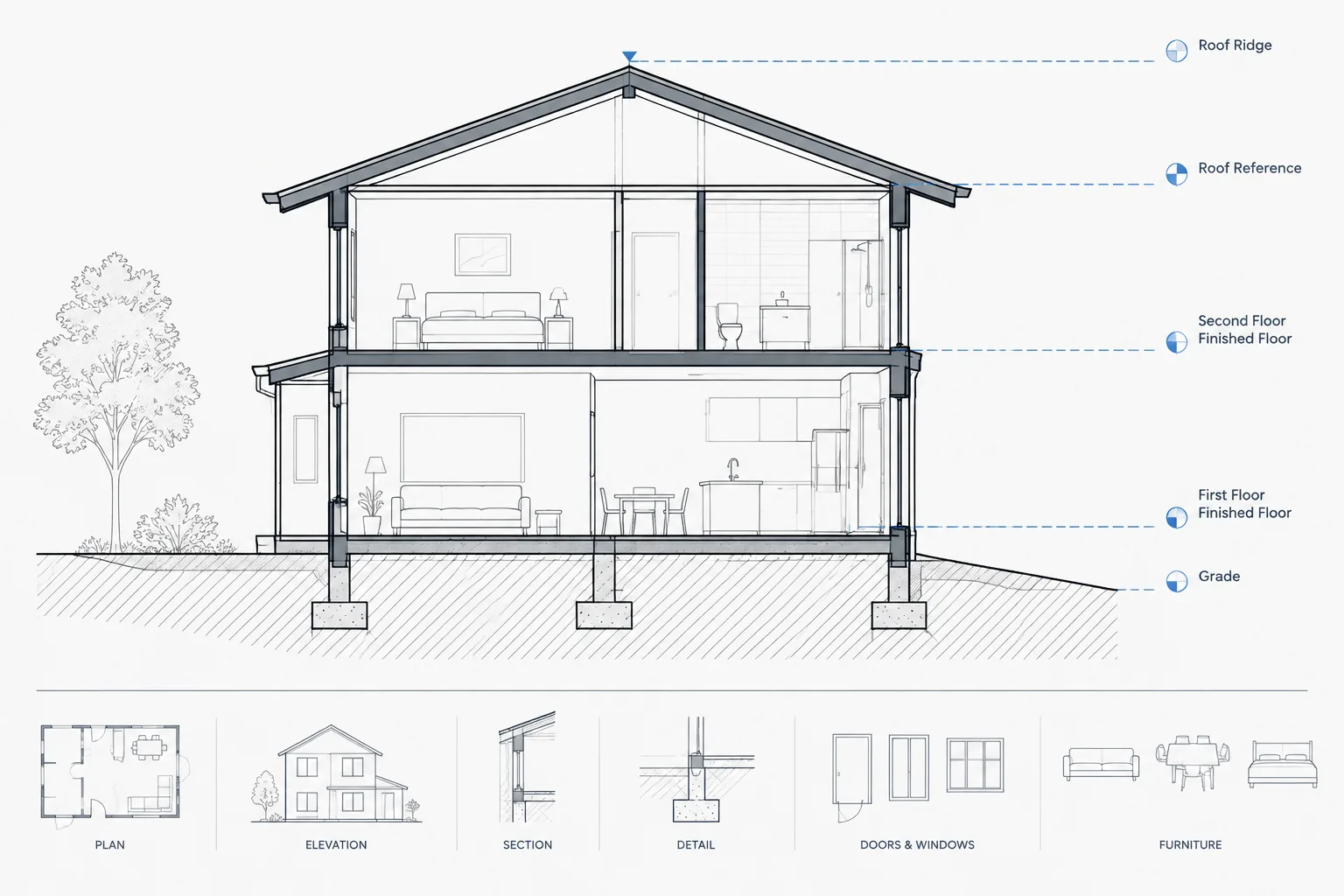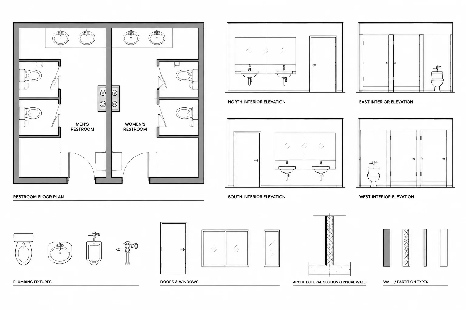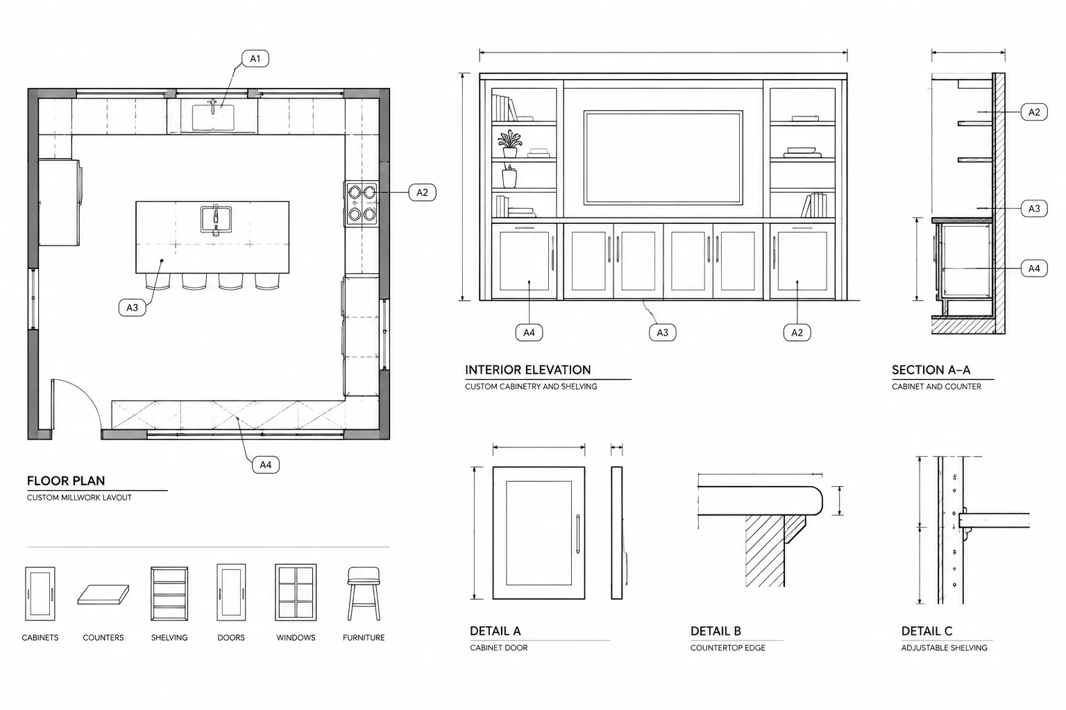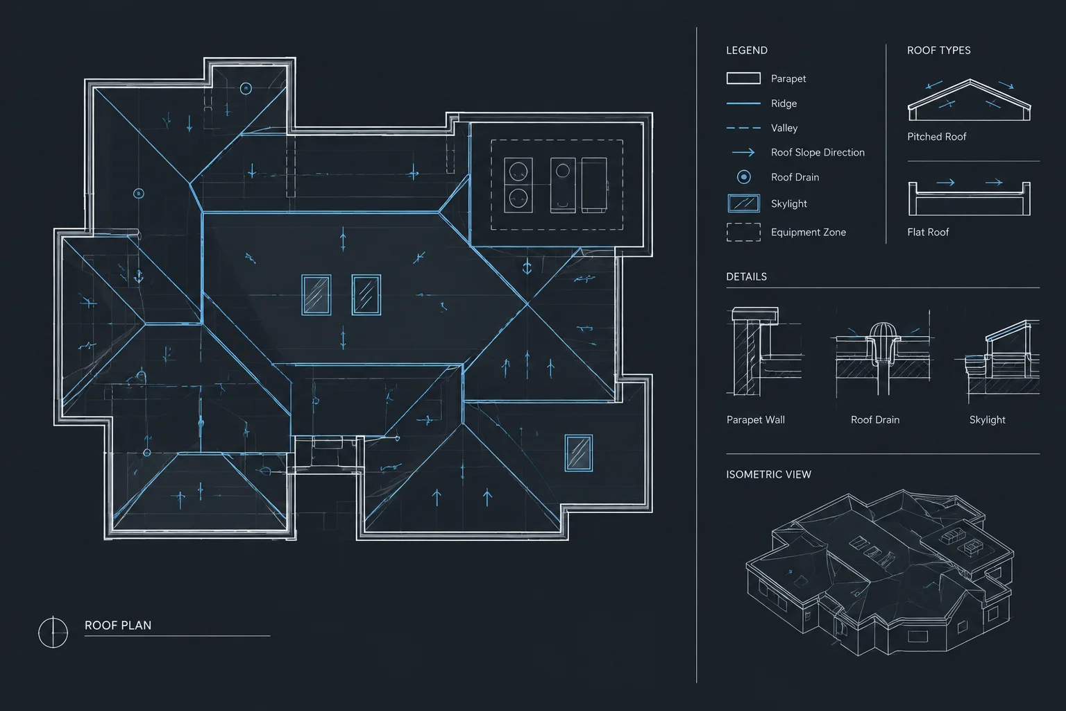
A drawing can look complete on screen and still contain coordination errors, missing references, plotting problems, or unnecessary data. Architectural DWG quality control is the structured review performed before a drawing is issued, shared with consultants, archived, or used as the basis for another phase of work.
The goal is not merely to make the file cleaner. A good review confirms that the visible drawing communicates the intended design, that its supporting CAD structure is dependable, and that recipients can open and interpret it without avoidable confusion. The process should cover both drawing content and file behavior.
Separate design review from CAD review
Design accuracy and CAD quality overlap, but they are not the same task. A wall may be drawn on the correct layer and still be in the wrong location. A room tag may be formatted correctly while identifying the wrong room. Conversely, the architectural content may be accurate even though the file contains duplicate geometry, unresolved references, or inconsistent plotting settings.
A dependable pre-issue check therefore uses two complementary review paths:
- Architectural review: Confirms the design intent, drawing relationships, room organization, openings, circulation, levels, and coordination with related documents.
- CAD review: Confirms file structure, references, layers, object properties, annotation behavior, sheet setup, plotting, and general file health.
Whenever possible, have someone other than the original drafter perform at least part of the review. A second person is more likely to notice familiar errors that the author has learned to overlook.
Start by confirming the issue scope
Before inspecting individual lines, establish what the drawing is supposed to show. Review the sheet title, drawing purpose, project phase, revision status, and expected issue package. A plan prepared for internal coordination may not contain the same information as a construction drawing, presentation plan, or consultant background.
Confirm which files and sheets belong to the issue. This avoids spending time correcting information outside the current scope and reduces the chance that an outdated drawing will be transmitted by mistake. If a transmittal or drawing index is used, compare it with the actual set rather than assuming the lists match.
Review the drawing at multiple scales
Quality control should not be performed at only one zoom level. Begin with a broad view of the entire plan or sheet, then move progressively toward detailed areas.
Overall composition
At a distant view, look for missing building areas, displaced references, isolated objects, unexpected extents, or annotation that appears far from the main drawing. Excessive drawing extents can indicate forgotten geometry or imported content located away from the project.
Room and circulation review
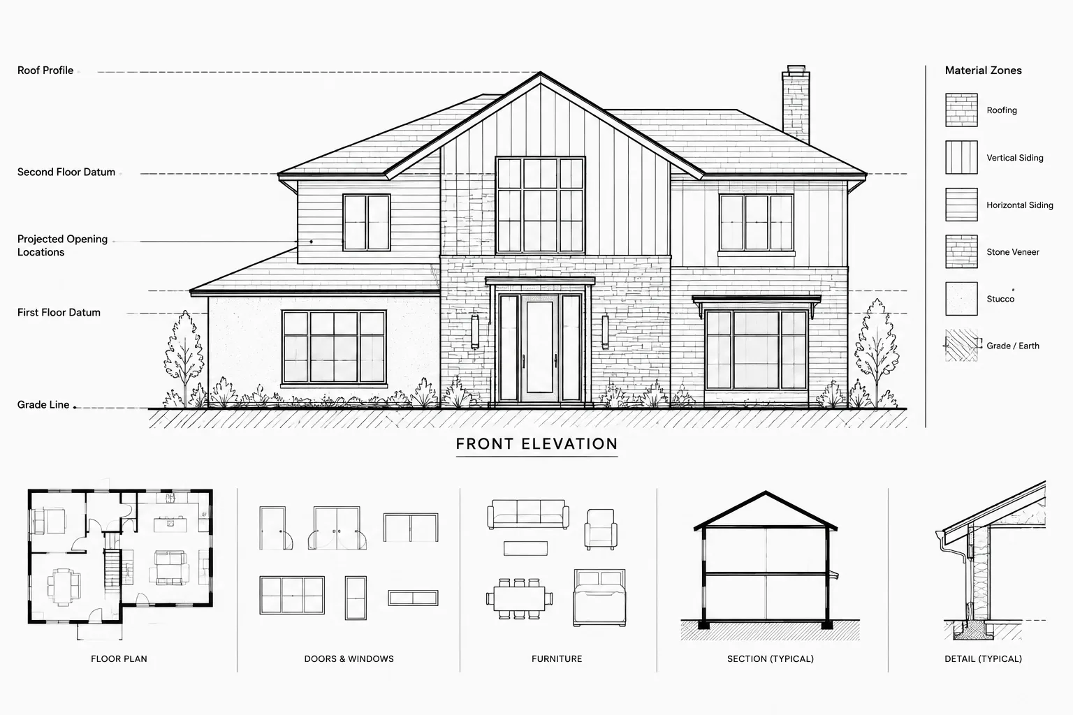
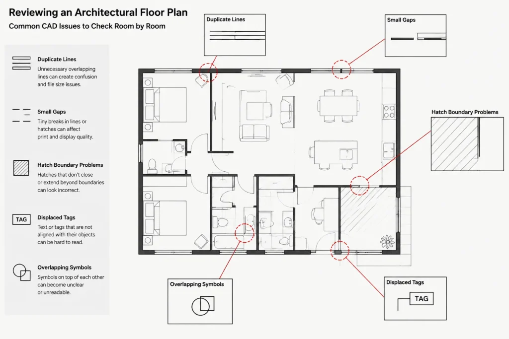
Move through the plan in a consistent route instead of jumping randomly between areas. Follow circulation paths and review each room for wall continuity, door placement, window coordination, fixture arrangement, tags, and dimensions. This room-by-room method makes omissions easier to identify.
Detailed junctions
Zoom into corners, openings, changes in wall type, stairs, shafts, millwork interfaces, and other busy conditions. Check whether lines meet cleanly, whether hidden geometry is showing through, and whether overlapping symbols obscure important information.
Check references and drawing origins
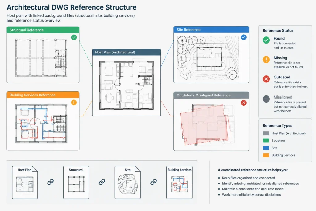
External references are a frequent source of issue problems. Open the reference manager and confirm that every required file is found, loaded, and using the intended path strategy. Look for obsolete references, circular relationships, duplicate attachments, and backgrounds that should not be included in the issued drawing.
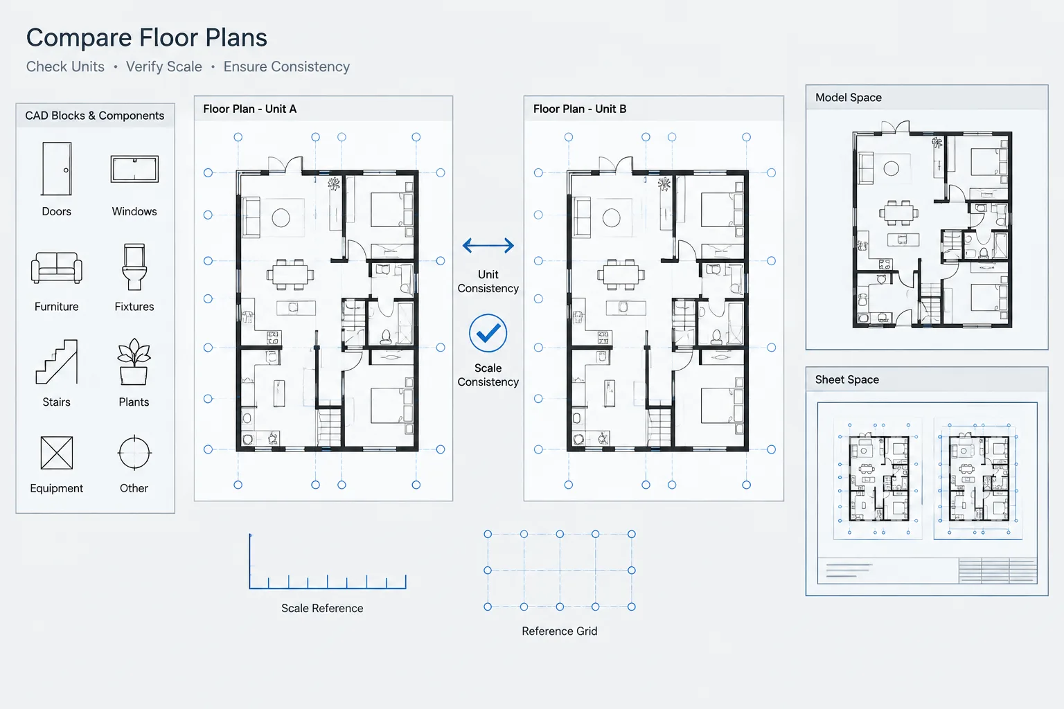
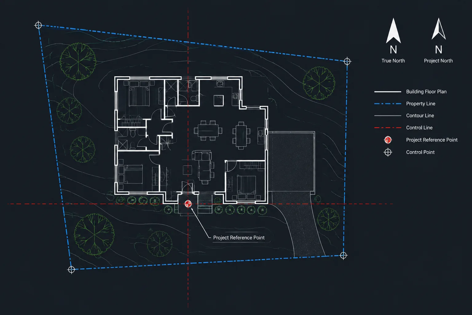
Visually compare referenced information with the architectural work. A reference can load successfully and still be outdated or incorrectly positioned. Check known alignment points such as grids, building corners, floor levels, structural elements, or survey control agreed upon by the project team.
Also review the file origin and coordinate approach. Do not move project geometry simply to make navigation easier without understanding how the file coordinates with other disciplines. Coordinate changes should be intentional, documented, and tested with the relevant backgrounds.
Inspect geometry for common drafting errors
Geometry review should focus on conditions that affect clarity, editing, measurement, and coordination. Common problems include:
- Duplicate lines placed directly over one another
- Very short line fragments left after trimming
- Open boundaries where a closed outline is expected
- Objects with unintended elevation or thickness values in a primarily two-dimensional drawing
- Lines that nearly meet but leave a small gap
- Blocks that have been unintentionally mirrored, stretched, or scaled
- Hatches extending across openings or beyond their intended boundaries
- Imported geometry composed of excessive segments
Automated cleanup tools can help identify some duplicate or overlapping objects, but they should not be applied blindly. Similar geometry may be intentional, particularly where multiple systems share a location or where graphic overlays are used. Save a recovery copy and inspect the results of any broad cleanup operation.
Audit layers and object properties
Reviewing the layer list alone is not enough. Inspect actual objects to confirm that they are assigned correctly and use the expected property strategy. Objects with manual color, linetype, transparency, or lineweight overrides may not follow the office plotting hierarchy even if they appear acceptable on screen.
Look for temporary working layers, imported layers, unexplained names, and layers that should have been removed or consolidated. Confirm that required information has not been hidden by frozen or turned-off layers in a viewport.
A layer audit should answer practical questions:
- Can another drafter understand where new objects should be placed?
- Can major drawing categories be isolated without selecting objects individually?
- Do renovation-status layers clearly separate existing, demolished, and new work where applicable?
- Are reference layers controlled intentionally rather than altered unpredictably?
- Will the visible hierarchy survive plotting in the intended output style?
Coordinate annotation and dimensions
Annotations should be reviewed as information, not decoration. Read every note, tag, and dimension that will be issued. Check spelling, abbreviations, terminology, numbering, and consistency with schedules and related views.
Dimensions need particular attention after design changes. Confirm that extension lines point to the intended references and that measured values have not been replaced with misleading text. Identify redundant dimension strings, conflicting values, and dimensions attached to unstable or inappropriate geometry.
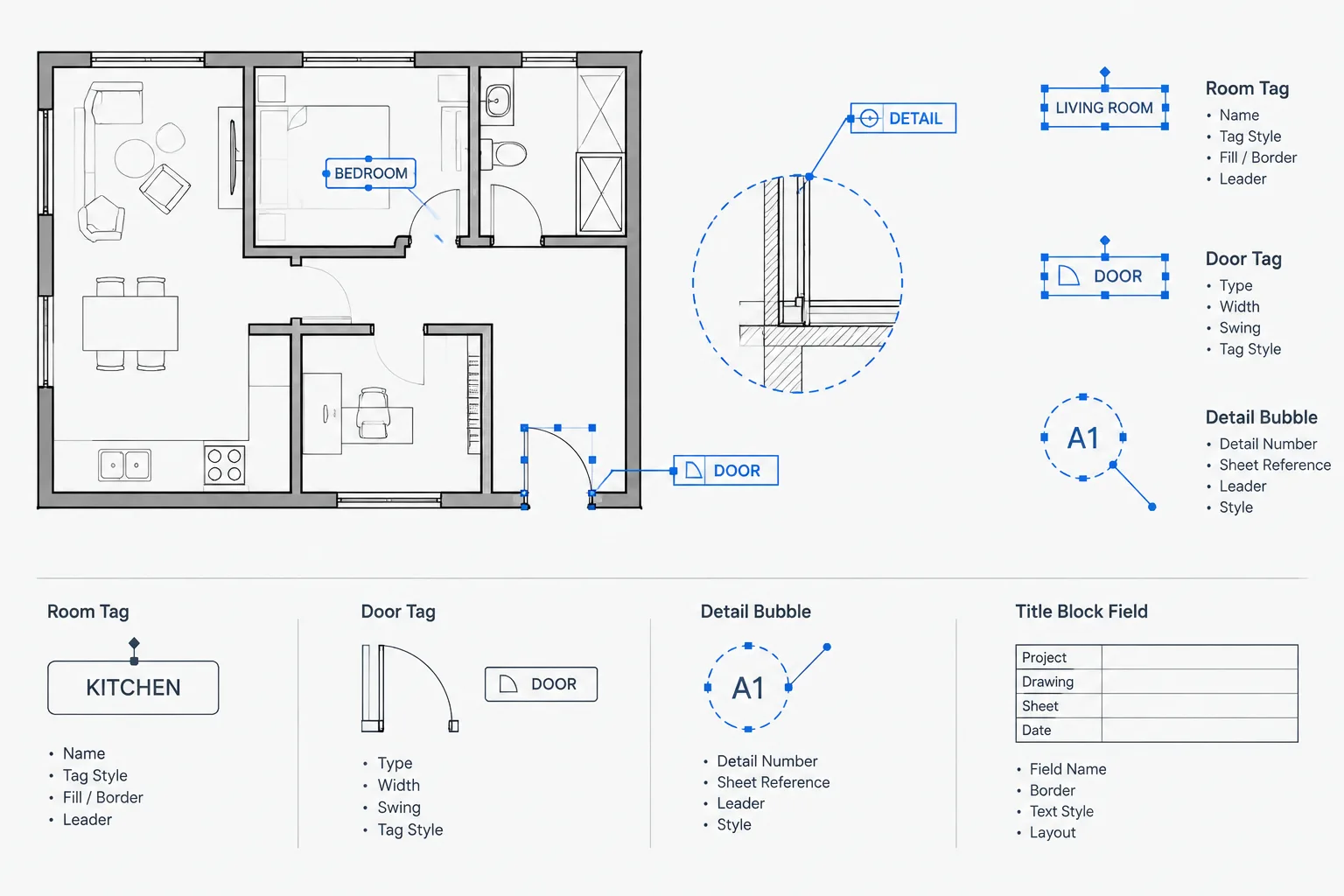
Review room tags, door tags, window tags, wall tags, section markers, elevation markers, and detail callouts against their corresponding schedules or destination drawings. A callout should lead to an existing and relevant view. A tag should identify the object actually shown, not a nearby object that was copied from an earlier layout.
Verify sheets and viewports
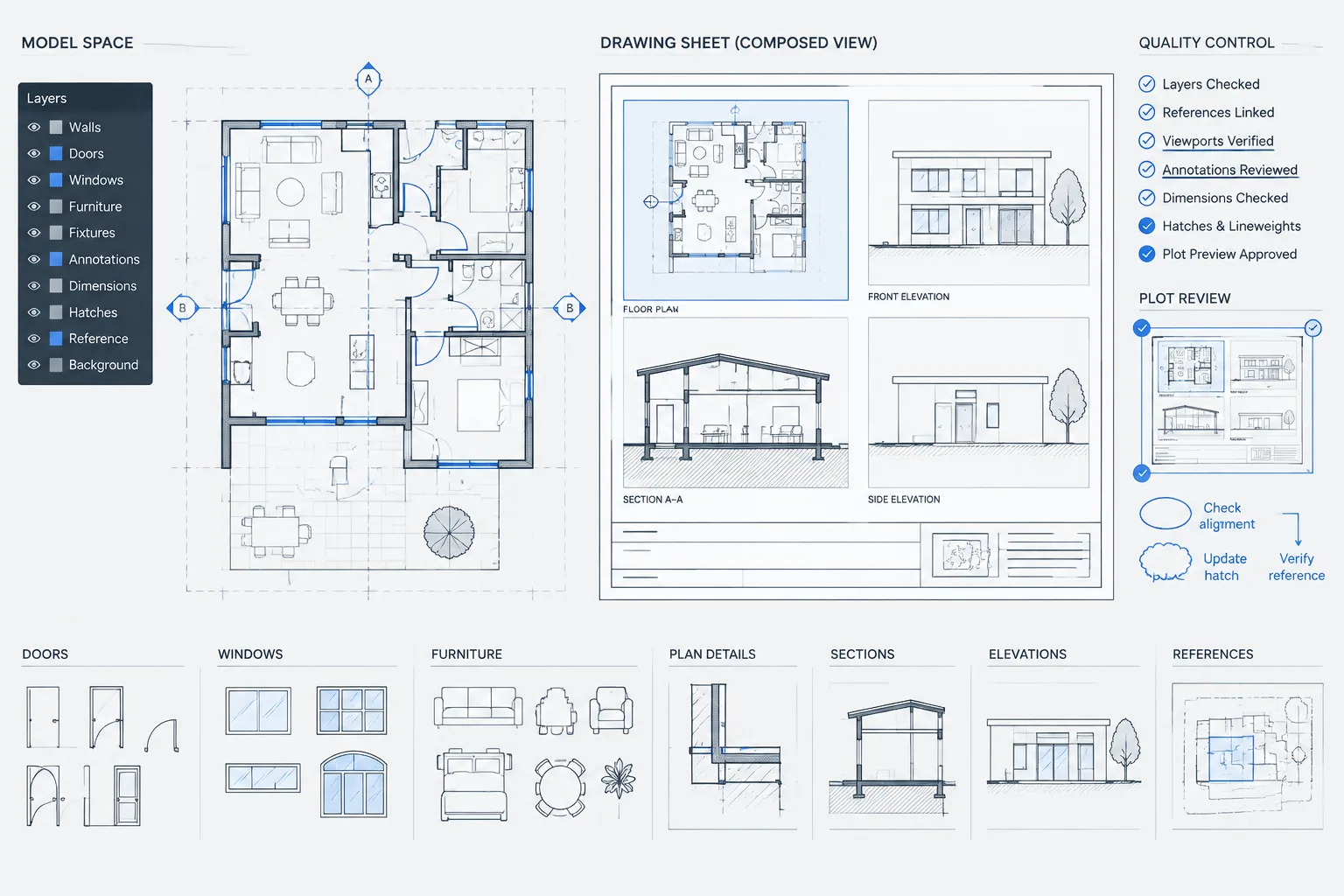
Move from model content to each paper-space layout included in the issue. Confirm that the correct views are visible, viewport boundaries are controlled, and viewport scales are intentional. A model may be accurate while the sheet displays an old area, an incorrect layer state, or an unintended crop.
Review the title block and sheet-specific information, including the sheet title, sheet number, project identification, issue information, and revision entries used by the office. Avoid assuming that fields or linked values are correct merely because they update automatically; the source information can also be wrong.
| Review area | What to verify | Typical warning sign |
|---|---|---|
| Viewport | View location, scale, layer visibility, and crop | Important content clipped or missing |
| Annotation | Readability and relationship to model elements | Text overlaps or displaced tags |
| Title block | Sheet identity and issue status | Copied information from another sheet |
| References | Required backgrounds display correctly | Unloaded or outdated information |
| Plot output | Line hierarchy, hatches, and sheet boundary | Objects visible on screen but absent in print |
Review the plotted output, not just the screen
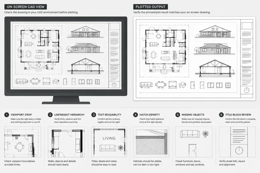
A PDF or physical plot reveals problems that are easy to miss in the editing environment. Generate the intended output and inspect every sheet at a full-sheet view and at readable magnification.
Confirm that lineweights establish a clear hierarchy, screened backgrounds remain legible, hatches do not become visually dominant, and text is readable. Look for clipped notes, missing symbols, solid-filled areas, broken linetypes, and elements that disappear because of plot-style or color behavior.
The plot review should also test visual priority. Primary cut elements should not be confused with secondary surface information, and existing or reference information should not overpower the work being communicated. The appropriate hierarchy depends on the drawing purpose, so evaluate clarity rather than relying only on preset settings.
Check file health before delivery
After content corrections are complete, perform a controlled file-maintenance pass. Use the CAD application’s diagnostic tools to check for drawing database errors. Remove unused content only after confirming that it is genuinely unnecessary. Purging can reduce clutter, but indiscriminate removal may eliminate definitions intended for later use or disrupt an office workflow.
Review blocks, text styles, dimension styles, linetypes, and other named definitions for obvious duplicates or imported variants. Standardization is useful, but renaming or replacing definitions immediately before issue can introduce new display problems. Make significant cleanup changes early enough to allow another plot review.
Save, close, and reopen the file as a final test. Resolve warnings rather than assuming the recipient will be able to do so.
Prepare a dependable sharing package
A working project folder may contain files that should not be transmitted and omit dependencies that recipients need. Build a deliberate delivery package containing the required drawings, references, images, plot configuration resources when appropriate, and any agreed supporting files.
Open or test the package from a separate location if possible. This helps expose path dependencies that remain hidden on the original workstation. Remove superseded files and clearly distinguish editable DWG files from published reference outputs.
Do not describe a drawing as approved, code compliant, or suitable for construction solely because it passed a CAD quality review. Technical approval, professional review, code analysis, and field verification are separate responsibilities.
Use a repeatable sign-off sequence
A concise checklist is more reliable than memory. A practical sequence is:
- Confirm the drawing purpose and issue scope.
- Review architectural content from overall plan to detailed junctions.
- Verify references, coordinates, and alignment.
- Inspect geometry, blocks, hatches, layers, and properties.
- Read and coordinate all annotations, dimensions, tags, and callouts.
- Check every sheet layout and viewport.
- Review the actual plotted output.
- Run controlled file diagnostics and cleanup.
- Test the final delivery package.
- Record who reviewed the drawing and what was corrected.
Architectural DWG quality control works best as an ongoing habit rather than a last-minute cleanup. Short reviews during drafting reduce the number of issues found before delivery, while a formal pre-issue check confirms that the drawing set and its underlying files communicate the same coordinated information.