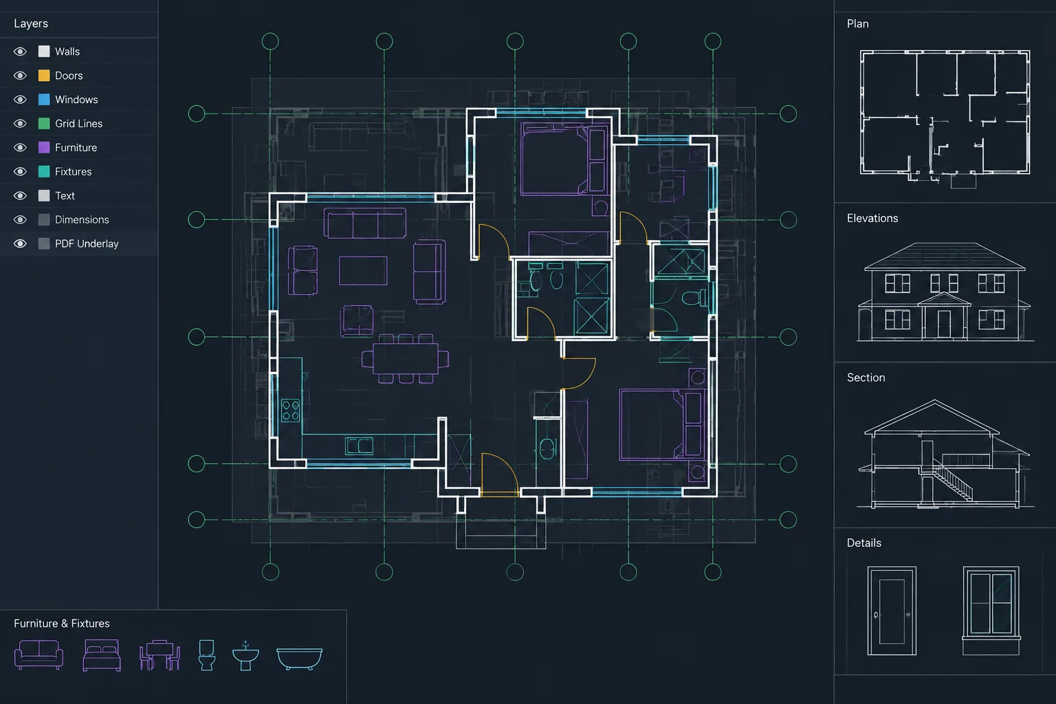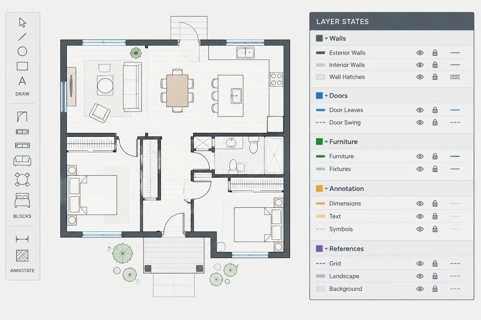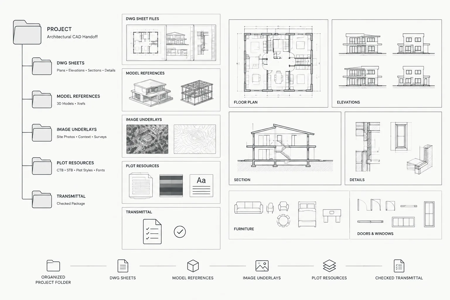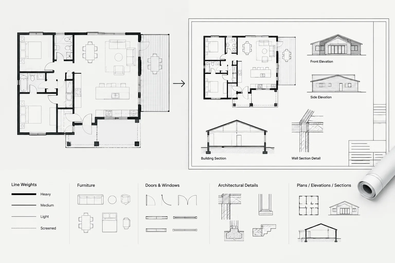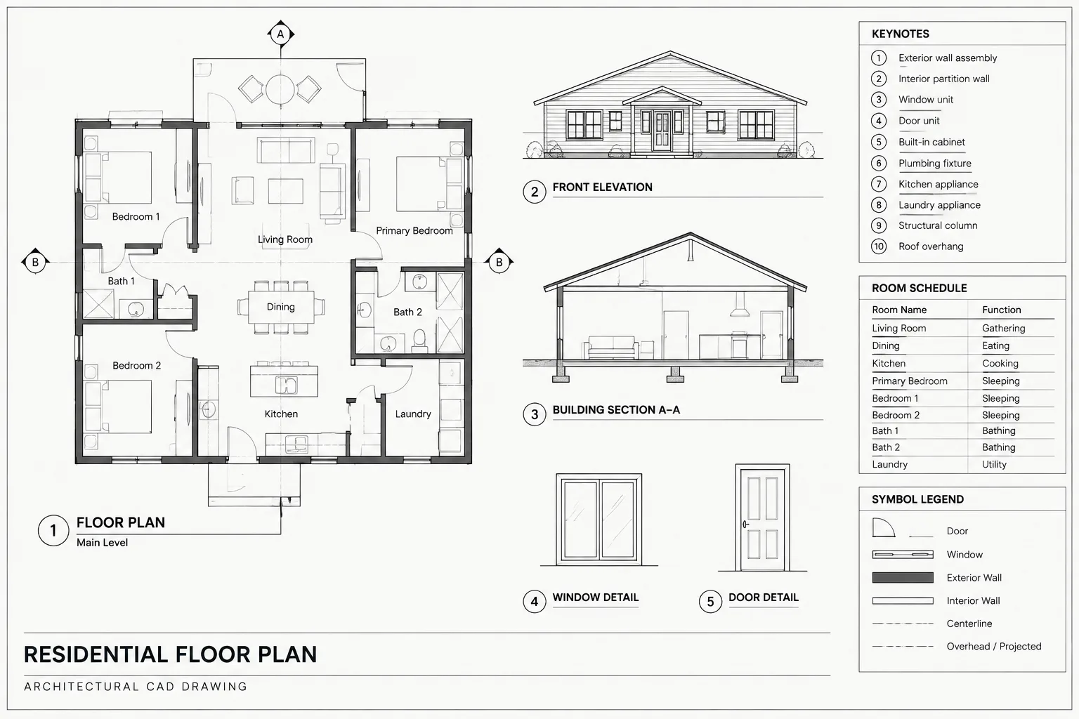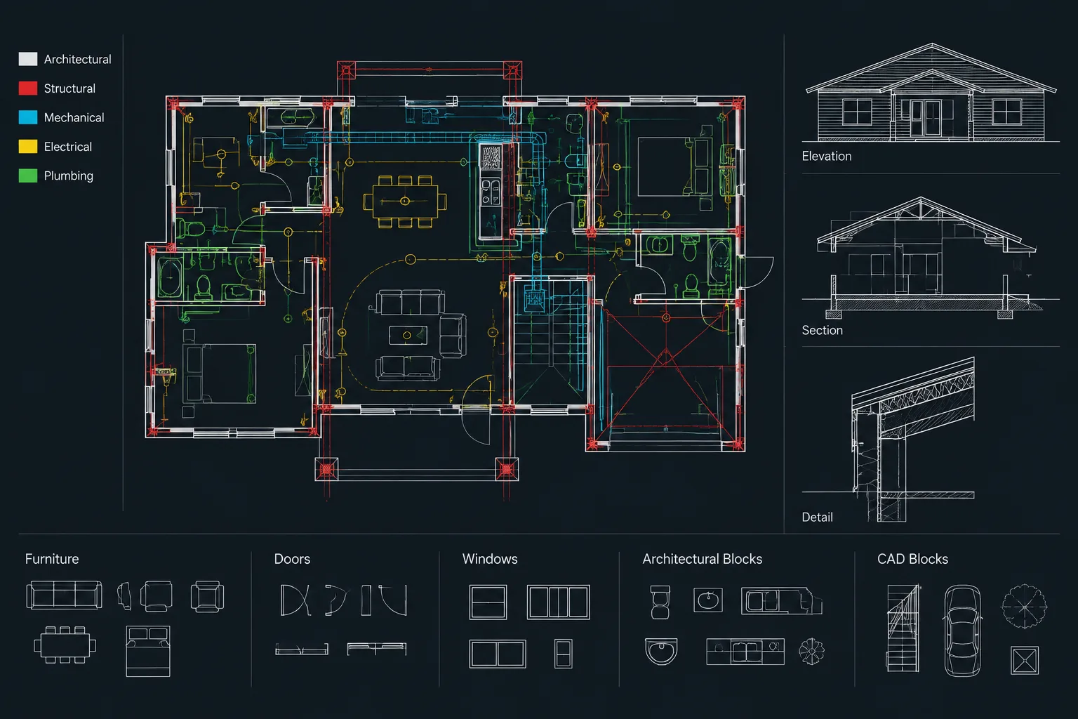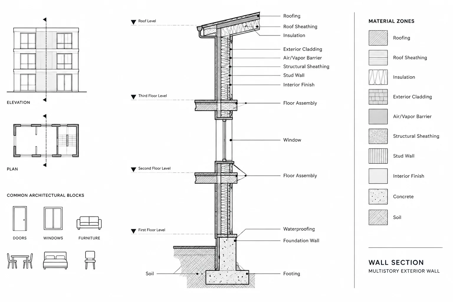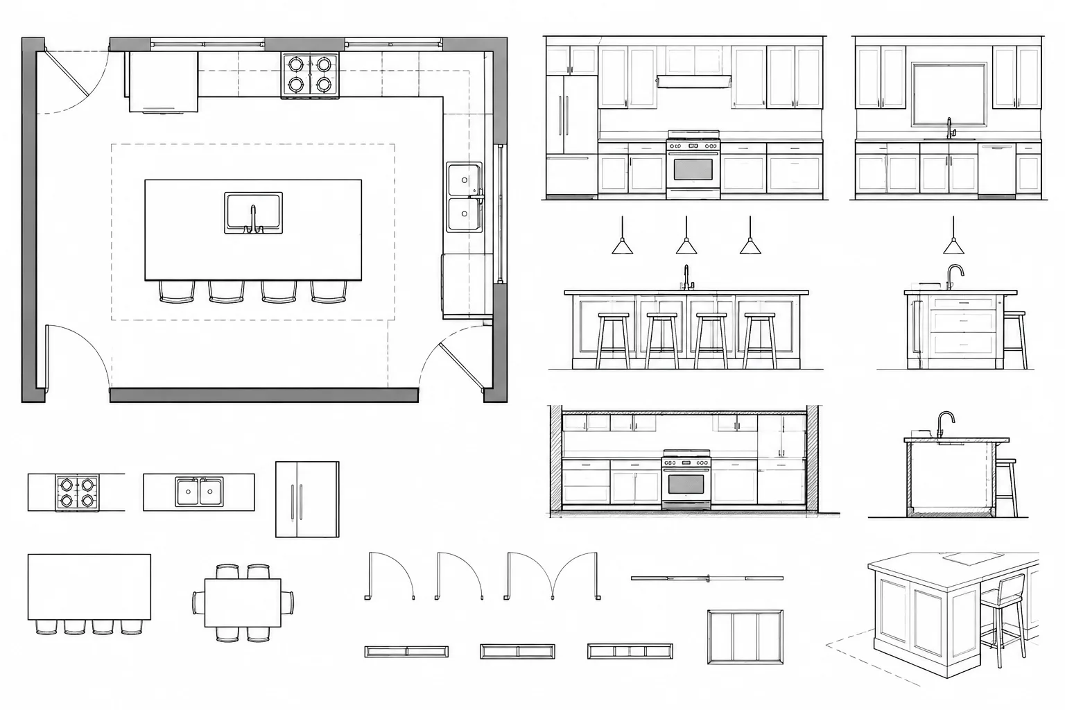
Drafting a kitchen plan in AutoCAD requires more than arranging visually convincing cabinet and appliance symbols. The drawing must connect architectural conditions, product information, operating space, utilities, elevations, and annotations without allowing assumptions to become hidden conflicts.
The following guide presents a practical sequence for developing and reviewing a coordinated kitchen drawing. It is useful for early layouts, design development, drafting exercises, and project documentation, but all product requirements and project-specific criteria still need independent verification.
A kitchen plan is more than a collection of cabinet and appliance blocks. It is a coordinated drawing that must account for walls, openings, work surfaces, storage, equipment, plumbing, ventilation, circulation, and adjacent rooms. A plan may look complete while still containing conflicts that become obvious only in elevation or section.
This workflow explains how to draft a kitchen plan in AutoCAD or another DWG-compatible CAD program. It focuses on drawing organization and coordination rather than prescribing universal dimensions. Cabinet modules, appliance sizes, required clearances, accessibility provisions, and construction requirements should always be checked against the project criteria, selected products, applicable regulations, and current consultant information.
Start with a reliable architectural background
Begin with the current floor plan rather than drawing the kitchen as an isolated composition. Confirm the drawing units, project origin, wall locations, room boundaries, structural elements, doors, windows, and known service locations before placing cabinetry.
If the architectural plan is externally referenced, keep the background separate from the kitchen design. This makes it easier to receive updated wall or opening information without rebuilding the kitchen drawing. If the plan is copied into a working file, preserve a clearly identified reference copy so changes can be compared later.
Review the room for elements that can affect the layout:
- Door leaves and their full swing paths
- Window widths, sill conditions, and trim
- Columns, pilasters, shafts, and wall offsets
- Plumbing supply and waste locations
- Exhaust or ventilation routes
- Electrical panels, outlets, and dedicated equipment connections
- Ceiling changes, soffits, beams, and bulkheads
- Connections to dining, service, pantry, or circulation areas
Organize the kitchen drawing by information type
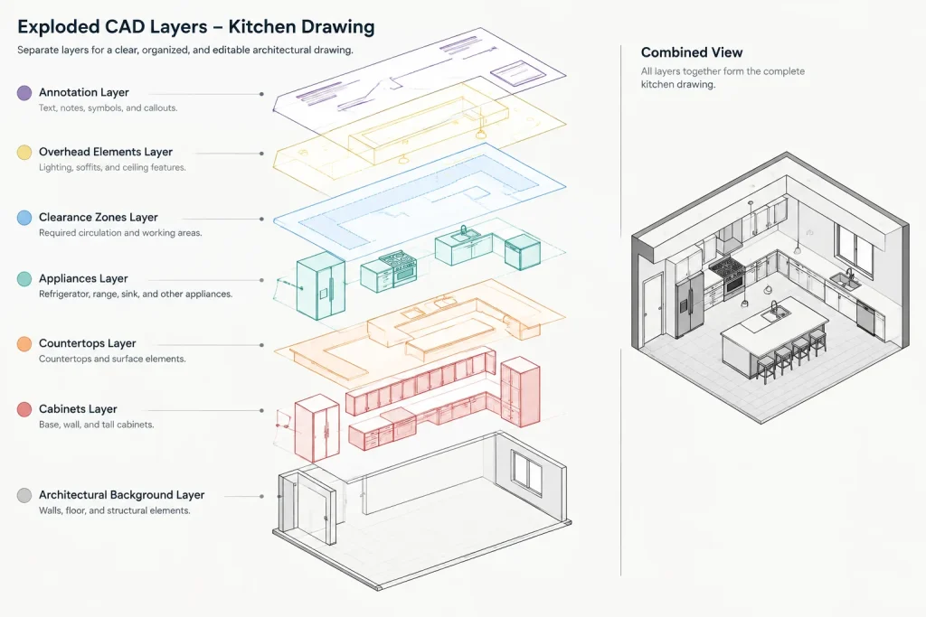
A clear layer structure allows the drawing to be edited, reviewed, and plotted without turning every component into the same visual weight. Use the project layer standard where one exists. Avoid creating near-duplicate layers simply because a downloaded block arrived with unfamiliar properties.
| Drawing information | Typical layer purpose | Coordination value |
|---|---|---|
| Base cabinets and tall cabinets | Primary casework outlines | Defines storage and work-surface locations |
| Wall cabinets and overhead storage | Objects above the plan cut plane | Prevents conflicts with windows, hoods, and soffits |
| Countertops and islands | Work-surface edges and overhangs | Clarifies usable surfaces and circulation limits |
| Appliances and fixtures | Equipment footprints and operating features | Supports product and utility coordination |
| Clearance zones | Non-plotting or lightly plotted working geometry | Tests doors, drawers, access, and circulation |
| Annotations | Tags, notes, dimensions, and callouts | Communicates design intent without altering geometry |
Keep temporary layout guides on dedicated construction layers. These can be hidden for plotting while remaining available during design development.
Establish cabinet runs before adding detail
Lay out the primary cabinet runs using simple rectangles or polylines. At this stage, concentrate on the relationship between cabinets, walls, openings, and movement through the room. Do not begin with decorative door panels, handles, or complex manufacturer blocks.
Separate the main cabinet categories:
- Base cabinets: floor-supported units beneath a work surface
- Wall cabinets: storage mounted above a counter or other base element
- Tall cabinets: full-height storage or equipment housings
- Islands and peninsulas: freestanding or projecting work areas that affect circulation on multiple sides
Use continuous cabinet-run geometry where practical, then divide it into modules after the overall arrangement works. This reduces the risk of optimizing individual cabinets while overlooking a poor room layout.
Account for wall conditions
Cabinet runs rarely fit perfectly between two walls. Corners may be out of square, wall finishes may vary, and door or window trim can reduce usable space. Show fillers, end panels, scribes, or closure pieces when they are part of the intended design rather than stretching a cabinet block to absorb an unexplained gap.
At exposed ends, indicate whether the cabinet has a finished panel, an overhanging counter, an adjacent partition, or an appliance side. These conditions often affect elevations and installation details.
Place fixtures and appliances using verified footprints
Appliances should not be represented by generic symbols alone when product selection affects the layout. Use verified manufacturer information when available, but keep the architectural drawing readable. The plan generally needs the overall footprint, door or drawer operation, required adjacent space, and relevant connection zone—not every internal product line.
For each appliance or fixture, consider:
- The body or installation opening
- Door, drawer, or lid movement
- Handles and projections
- Adjacent panels or clearances needed for operation
- Plumbing, power, gas, or ventilation connections where applicable
- Service access and replacement path
- Relationship to counters and cabinet faces
Downloaded CAD blocks should be checked before insertion. Confirm units, scale, insertion point, layer behavior, linework, and actual dimensions. A detailed-looking refrigerator or range block is not evidence that it matches the selected product.
Draw operating and clearance zones
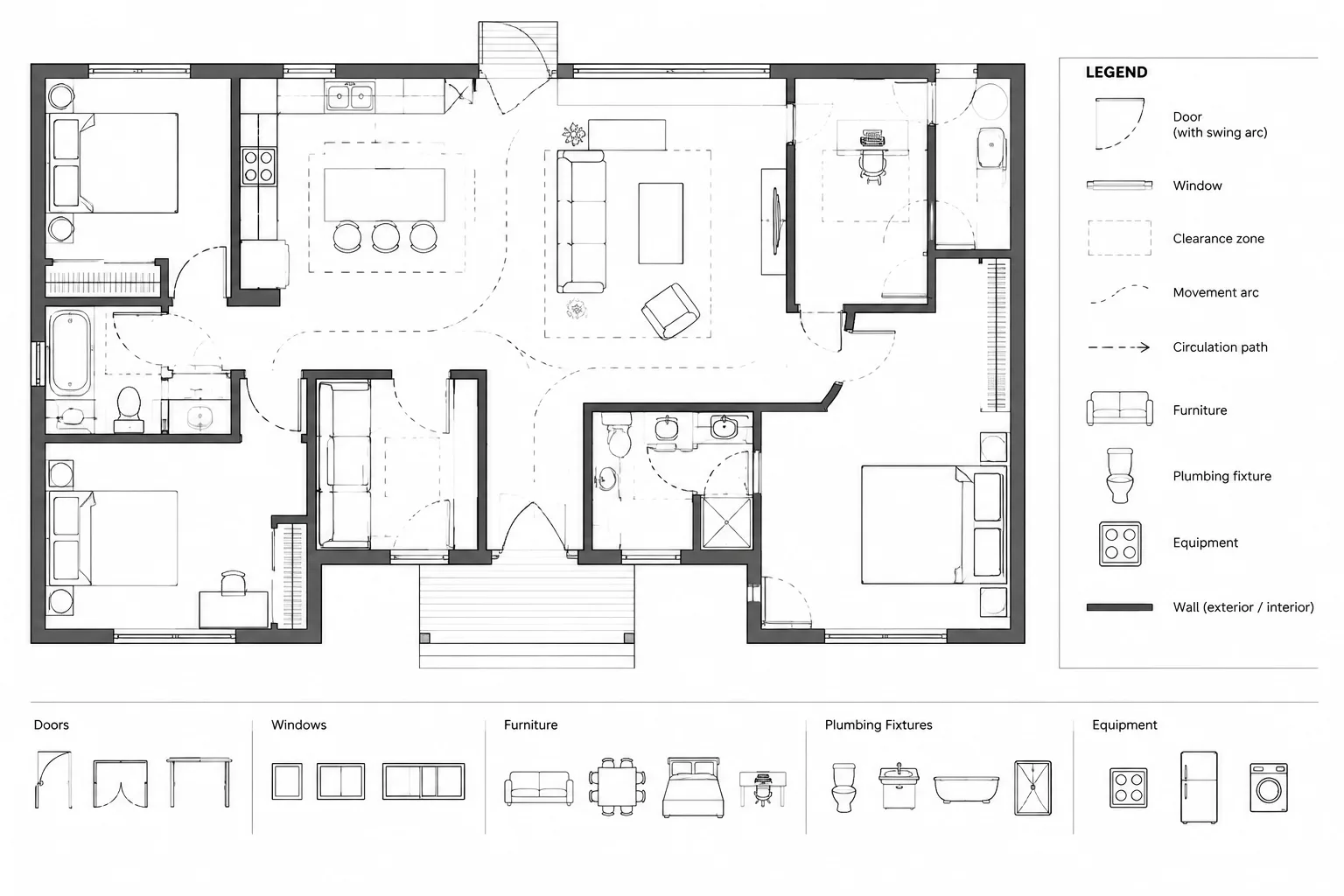
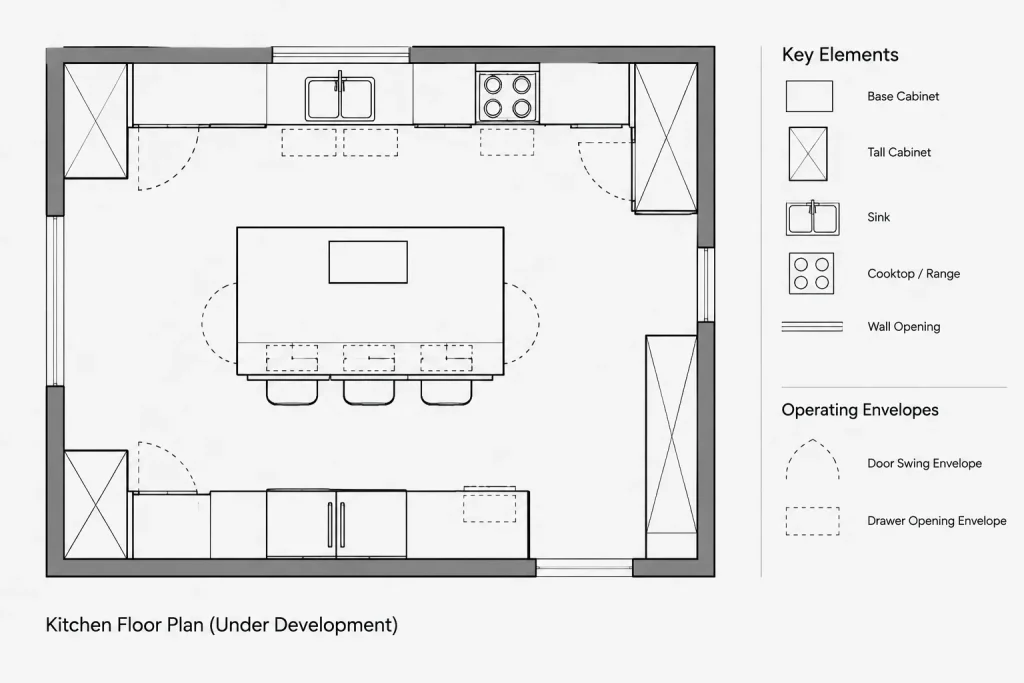
One of the most useful kitchen-planning techniques is to draw temporary operating envelopes. These are simple arcs, rectangles, or polylines representing open appliance doors, cabinet drawers, passage areas, and standing zones.
Test likely conflicts such as:
- An appliance door colliding with an island
- Opposing doors or drawers blocking each other
- A dishwasher door obstructing a primary route
- A refrigerator door opening against a wall or projecting handle
- Stools interfering with circulation behind an island
- A corner cabinet being inaccessible beside another appliance
- A door swing entering the active kitchen work area
Clearance geometry is a design aid, not proof of regulatory compliance. Required widths and accessibility conditions depend on project use, jurisdiction, occupancy, and adopted criteria. Keep these zones easy to revise as the design and product selections change.
Coordinate countertops, sinks, and work areas
Once the cabinet layout is stable, draw the countertop as a separate element. This helps communicate edges, end conditions, backsplashes, joints, overhangs, and cutouts. Avoid relying only on cabinet outlines to imply the counter shape.
Locate sinks and other counter-mounted fixtures relative to the cabinet below, nearby windows, plumbing routes, and usable work surface. A sink centered on a window may appear orderly in plan but still require review against sash operation, sill height, trim, and faucet geometry.
Review the relationship among food storage, cleaning, preparation, and cooking areas without treating a single planning diagram as universally correct. The appropriate arrangement depends on the room, household or operational needs, appliance types, accessibility goals, and whether the kitchen is residential, commercial, or shared.
Develop elevations alongside the plan
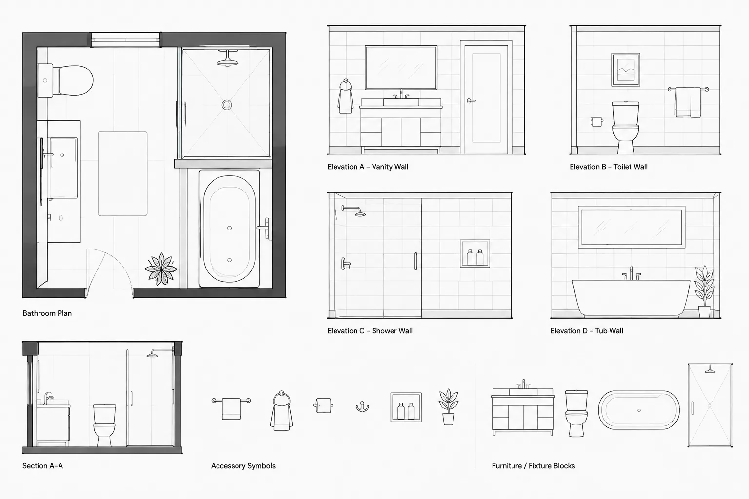
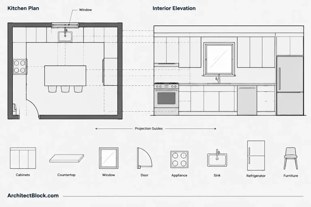
Do not wait until the plan is finished before producing kitchen elevations. Elevations reveal conflicts that a floor plan cannot show, including cabinet heights, window relationships, appliance alignment, backsplash limits, open shelving, hood placement, soffits, and upper-cabinet coordination.
Create an elevation for each significant cabinet run. Project major horizontal and vertical control lines from the plan, then add:
- Base, wall, and tall cabinet divisions
- Countertop and backsplash extents
- Appliance faces and control areas
- Open shelves and finished panels
- Windows, doors, trim, and wall returns
- Ceiling lines, soffits, and bulkheads
- Material changes and key notes
Use matching identifiers between the plan and elevations. If a cabinet changes width or position in plan, update the related elevation immediately rather than allowing parallel versions to develop.
Add dimensions and identifiers after coordination
Dimension the information needed to locate and build the work, but avoid repeating the same dimension across several drawings unless repetition serves a clear purpose. Use stable references such as wall faces, grid lines, opening edges, or established centerlines rather than dimensioning everything from movable equipment.
A kitchen drawing may identify cabinet runs, individual units, appliances, fixtures, finishes, and elevation references. The identification system should connect logically to the schedules, specifications, or millwork information used on the project. Do not assign a tag that implies a selected product if the item is still generic.
Perform a final kitchen CAD review
Before issuing or sharing the drawing, review the kitchen at both working scale and intended plot scale. A compact quality-control pass should include the following:
- Confirm that wall, door, and window backgrounds are current.
- Check cabinet ends, corners, fillers, and exposed panels.
- Verify appliance footprints against current product information.
- Test doors, drawers, seating, and circulation with operating envelopes.
- Compare every cabinet run with its corresponding elevation.
- Review plumbing, ventilation, electrical, ceiling, and structural constraints.
- Remove duplicate lines and unnecessary detail from imported blocks.
- Confirm that overhead cabinets and features use an understandable line convention.
- Check tags, notes, callouts, and dimensions for conflicts.
- Plot a review sheet to confirm lineweights and legibility.
Build the drawing from coordinated decisions
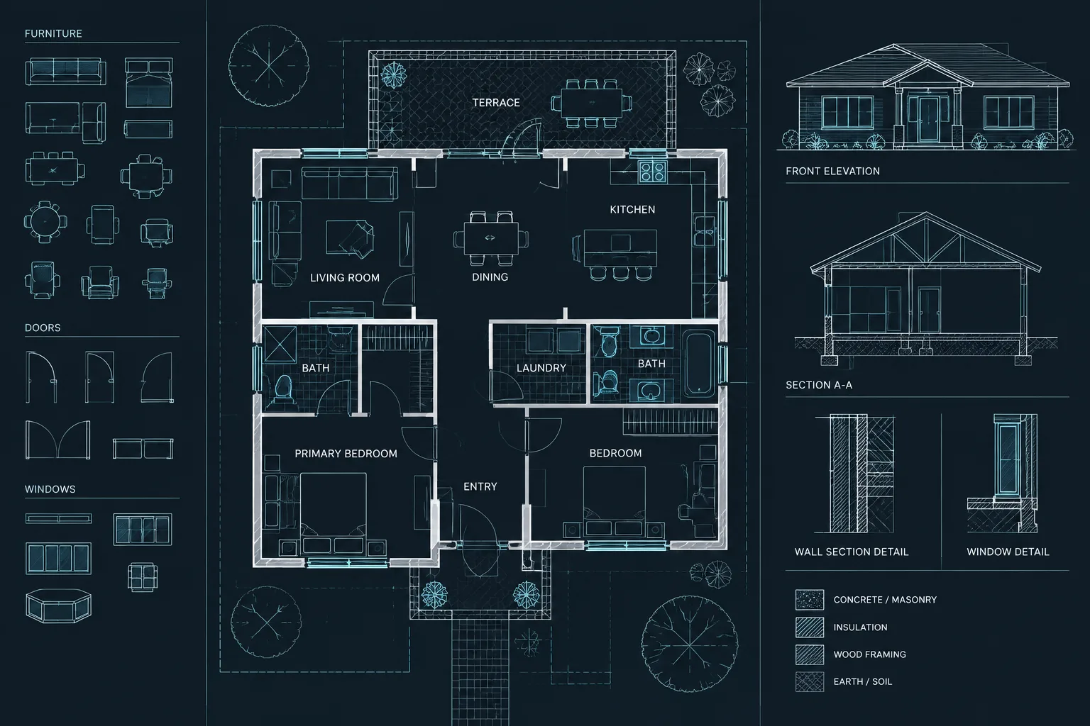
An effective kitchen plan develops from large relationships to smaller components: architectural background, cabinet runs, appliances, operating zones, countertops, elevations, and annotation. Following that order keeps the CAD file flexible and makes design changes easier to manage.
Generic DWG blocks can accelerate early planning, but they should remain placeholders until their dimensions and operating requirements are verified. Treat the plan, elevations, sections, equipment information, and consultant drawings as connected views of the same design. That coordination—not the amount of detail in any single block—is what makes a kitchen drawing useful.
Track what is fixed, provisional, and verified
A useful coordination habit is to distinguish confirmed information from working assumptions. Walls and openings may come from the architectural background, while appliance footprints, cabinet divisions, utility points, or finish conditions may remain provisional. A polished block should not be interpreted as confirmed information simply because it contains detailed linework.
Use clear notes, layer conventions, or status markers to identify items awaiting review. When a product or cabinet configuration is confirmed, compare it with the placeholder rather than replacing the symbol without checking the surrounding layout.
Review changes across connected drawings
Kitchen revisions often affect more than the plan. Moving an appliance can alter cabinet divisions, countertop cutouts, elevation composition, utility coordination, ventilation routing, and annotation. Changing a window or wall return can have similar consequences.
After each significant revision, review the affected cabinet run as a coordinated set of plan, elevation, section, equipment, and service information. This change-based review is usually more reliable than waiting for a final drawing check, when related conflicts may already be distributed across several views.
Keep the DWG readable for the next user
A kitchen drawing should remain understandable to someone who did not create it. Use consistent object properties, recognizable insertion points, controlled block detail, and clear distinctions between permanent geometry and temporary clearance studies. Remove redundant imported linework, but retain the information needed to understand equipment operation and installation relationships.
The strongest CAD file is not necessarily the most detailed one. It is the file in which current information, unresolved assumptions, and drawing relationships can be identified and revised without unnecessary reconstruction.
Kitchen Plan Drafting FAQ
Should cabinets or appliances be placed first?
Begin with the room constraints and broad cabinet runs, then introduce verified appliance and fixture footprints while the arrangement is still flexible. Cabinet modules and appliance locations should be refined together because each can change the other.
Can a downloaded kitchen CAD block be used without editing?
It should be inspected before use. Check its units, overall size, insertion behavior, layers, linework, and operating geometry. Treat it as a placeholder unless it has been matched to the selected product or project information.
Why should kitchen elevations be developed early?
Elevations reveal vertical relationships that are difficult to judge in plan, including cabinets near windows, countertop and backsplash limits, appliance faces, shelving, hoods, soffits, and ceiling conditions. Developing them alongside the plan helps expose conflicts before annotation is finalized.
How should wall cabinets appear in a kitchen plan?
Use a consistent overhead line convention that distinguishes them from objects cut or viewed directly in plan. The exact graphic treatment should follow the project drafting standard and remain legible at the intended plot scale.
What should be checked after an appliance changes?
Review the installation opening, adjacent cabinets, panels, countertop conditions, door or drawer operation, service access, utility connections, elevations, tags, and notes. A product change can affect several drawing views even when its plan footprint appears similar.
Are operating envelopes the same as required clearances?
No. Operating envelopes are drafting aids used to visualize doors, drawers, access, and movement. Compliance requirements must be established from the applicable project criteria, regulations, accessibility provisions, and verified product information.