
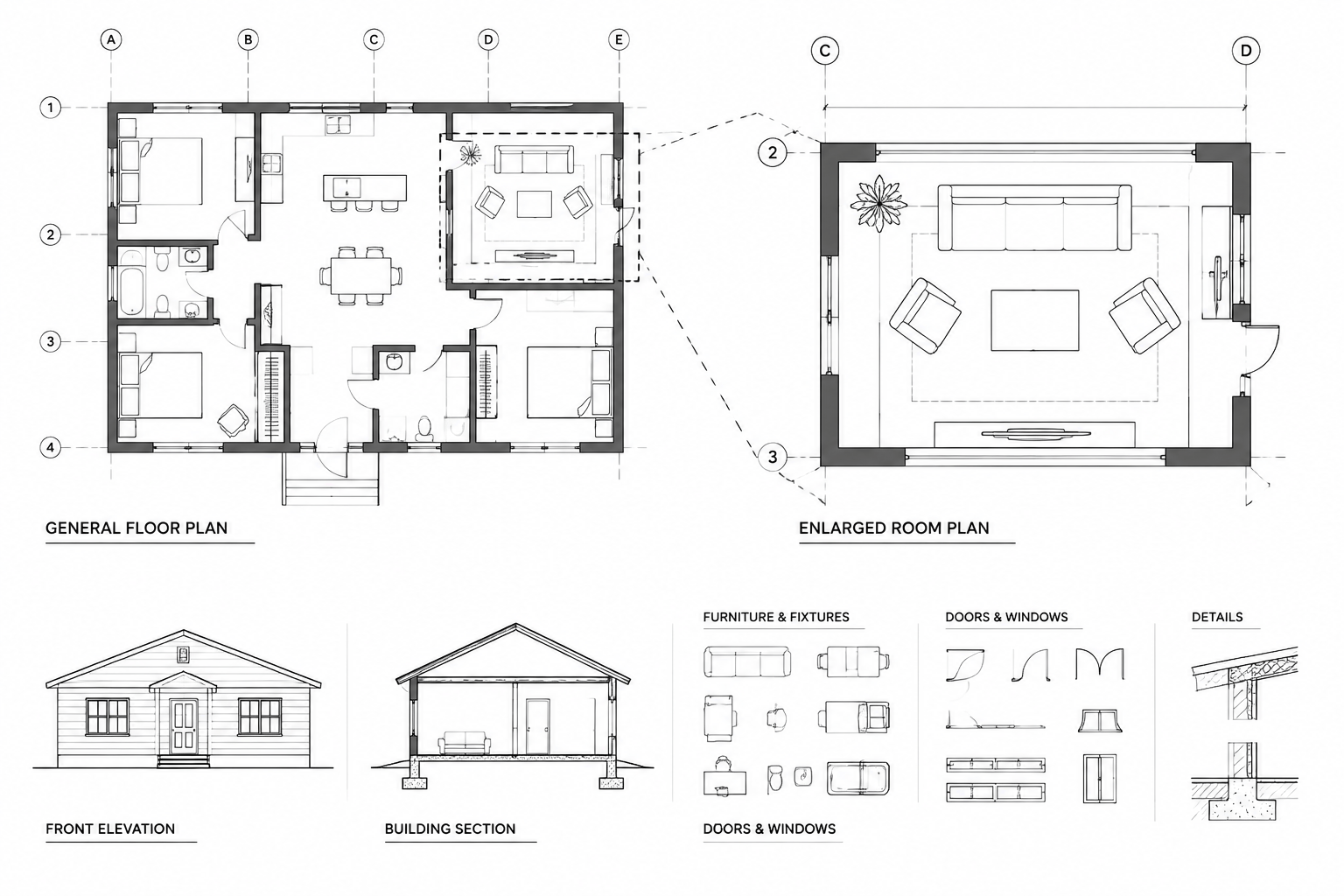
Enlarged plans are used when a general floor plan cannot clearly show the information needed for a compact or detail-heavy area. Restrooms, kitchens, reception counters, stairs, equipment rooms, and built-in casework zones are common examples. The enlarged view gives dimensions, notes, fixtures, clearances, and construction relationships more room without overcrowding the main plan.
Creating an enlarged plan is not simply a matter of scaling up a portion of a drawing. It requires a clear source, a deliberate callout boundary, coordinated references, and an annotation strategy suited to the new view. The following workflow explains how to create enlarged plan callouts in CAD while keeping the general plan and enlarged drawing synchronized.
What an Enlarged Plan Should Accomplish
An enlarged plan should clarify a defined area while maintaining an obvious relationship to the overall building plan. A reader should be able to identify where the enlarged area is located, find the corresponding view, and understand which information belongs in each drawing.
A useful enlarged plan typically provides:
- A recognizable portion of the surrounding walls or grid system
- Fixtures, equipment, doors, casework, and other relevant components
- More detailed dimensions than the general plan
- Keynotes, material notes, or assembly references where required
- Section, elevation, or detail markers associated with the area
- A view title and drawing reference that match the originating callout
The view should add information rather than repeat every note already visible elsewhere. The general plan establishes overall location and organization; the enlarged plan communicates local coordination.
Decide Whether an Enlarged View Is Necessary
Before creating another drawing, determine whether the area truly needs enlargement. Adding unnecessary views creates more references to maintain and more opportunities for conflicting information.
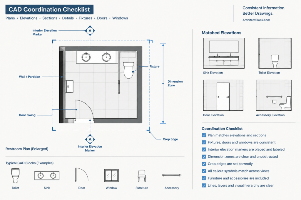
An enlarged plan is usually helpful when dimensions, tags, or symbols overlap at the general plan’s intended plotted scale. It may also be appropriate when several disciplines or drawing types must coordinate within a small zone. A restroom group, for example, may involve architectural partitions, plumbing fixtures, accessories, door swings, finishes, and interior elevations.
If the area only requires one isolated construction condition, a detail or section may be more effective. If the issue is primarily vertical, an interior elevation may communicate it better. Select the view type according to the information that must be explained.
Establish a Reliable Source for the Enlarged Plan
The enlarged view should originate from the same current geometry used for the main floor plan. Avoid independently redrawing walls, doors, and fixtures for the enlarged plan. Separate copies can quickly diverge as the design changes.
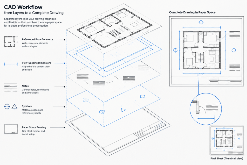
Common approaches include displaying the same model-space geometry through a dedicated paper-space viewport or referencing a coordinated floor-plan file into a separate enlarged-plan drawing. The appropriate method depends on the project’s file structure, team size, and sheet organization.
Whichever method is used, follow three principles:
- Maintain one authoritative source for primary building geometry.
- Place view-specific notes and dimensions where their intended display can be controlled.
- Avoid editing referenced background geometry merely to improve one enlarged view.
When a separate drawing file is necessary, use consistent insertion points, rotation, units, and reference paths. Confirm that the enlarged view aligns with the current architectural base before annotation begins.
Create the Callout Boundary on the General Plan
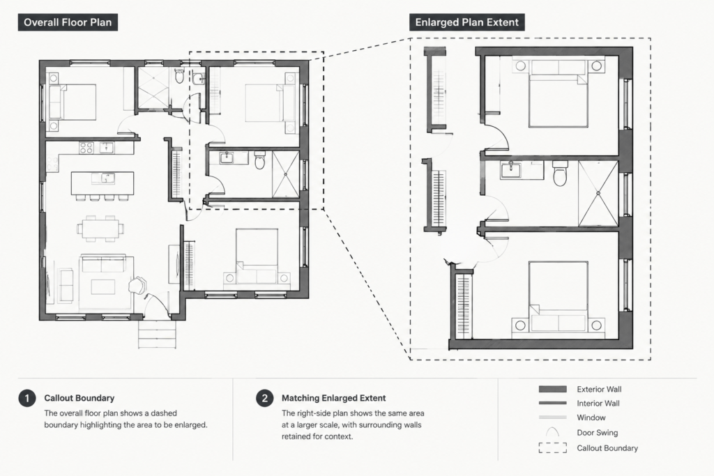
The callout boundary identifies the portion of the building shown in the enlarged view. Draw it around the relevant area without obscuring critical plan information. Its shape should be easy to follow and should not imply that walls or rooms outside the boundary are unimportant to the enlarged view’s context.
Include enough surrounding geometry to orient the reader. A boundary cut tightly against the room faces may remove useful references such as corridor walls, adjacent doors, column lines, or room labels. Conversely, an excessively large boundary can make the enlarged view less focused.
The callout symbol should contain the drawing reference used by the project’s sheet-indexing system. Keep the symbol legible at the plotted size of the general plan. Place it where it can be read without crossing dimensions, door tags, or other markers.
Use a Dedicated Callout Layer
Place callout boundaries and reference symbols on a clearly named annotation layer. This makes their visibility, lineweight, and plotting behavior easier to manage. Do not place them on wall, fixture, or miscellaneous text layers simply because those layers are already visible.
If the office uses separate layers for callout outlines, view references, and titles, follow that convention consistently. The exact naming system is less important than predictable use throughout the project.
Build the Enlarged View
Frame the enlarged view so its orientation is immediately understandable. Keeping the same orientation as the general plan is often the clearest approach. Rotating the enlarged view may improve sheet fit, but it can also slow plan reading. If rotation is necessary, provide enough contextual geometry and directional information to prevent confusion.
Crop or clip the displayed background thoughtfully. Show complete wall intersections, door openings, and nearby reference elements whenever they help explain the space. Avoid crop limits that run directly through important symbols or leave unexplained fragments at the edge of the view.
Set the view to a plotted scale that supports the required level of annotation. Then test the actual sheet output. A view that appears spacious on screen may still be difficult to read when plotted.
Control Information Between the General and Enlarged Plans
A strong drawing set assigns information intentionally. Overall dimensions, major wall locations, room names, and circulation relationships generally belong on the overall plan. Local fixture spacing, accessory locations, casework dimensions, and detailed partition relationships are better suited to an enlarged plan.
| Information | Typical primary location | Coordination concern |
|---|---|---|
| Overall building dimensions | General floor plan | Do not restate them locally unless needed for interpretation. |
| Room and area identification | Both views when useful | Use matching names or numbers. |
| Fixture and equipment layout | Enlarged plan | Coordinate with schedules and consultant drawings. |
| Local partition dimensions | Enlarged plan | Dimension from stable references rather than loose objects. |
| Door identification | General plan or both | Keep tags consistent with the door schedule. |
| Interior elevation markers | Enlarged plan | Verify that referenced views exist and match their titles. |
Duplicate information is sometimes necessary for navigation, but duplicated dimensions or notes should be minimized. When the same requirement appears in multiple locations, every revision must be coordinated.
Annotate for the Enlarged View’s Scale
Use text, dimensions, leaders, and symbols that produce the intended plotted size. Do not enlarge annotation merely because the plan geometry appears larger on screen. Apply the project’s annotation system consistently so enlarged plans read as part of the same drawing set.
Arrange dimensions in logical strings. Start with the information most closely related to the objects being located, then move broader dimension strings outward. Keep text clear of fixture outlines, door swings, and hatch patterns. Where possible, use common reference faces or centerlines so the dimensional logic can be checked easily.
Notes should explain conditions that cannot be communicated efficiently through geometry or standard symbols. Avoid using notes to compensate for inaccurate drawing. If a partition, fixture, or opening must be located precisely, represent and dimension it clearly.
Coordinate Related Views and References
Enlarged plans often become hubs for interior elevations, wall sections, millwork details, and finish references. Check every marker in both directions: the source symbol should point to the correct destination, and the destination title should identify the correct originating area.
Use a consistent room name, number, or area designation across the floor plan, enlarged plan, elevations, schedules, and finish information. If a room changes name or is divided during design, search for references throughout the drawing set rather than updating only the visible plan label.
Common Enlarged-Plan Problems
- Redrawn background geometry: Independent copies of walls and doors become inconsistent after revisions.
- Overly tight callout boundaries: The enlarged plan lacks context and is difficult to locate on the general plan.
- Excessive duplication: Notes and dimensions appear in multiple views and no longer agree.
- Uncontrolled layer visibility: Unnecessary grids, hatches, tags, or consultant information clutter the view.
- Ambiguous cutoffs: Fixtures or construction elements are partially shown at the crop edge without explanation.
- Broken references: Callout numbers, sheet references, and view titles do not match.
- Poor plot testing: Annotation looks acceptable on screen but becomes crowded or faint on the issued sheet.
Final CAD Coordination Checklist
- Confirm that the enlarged plan uses the current floor-plan geometry.
- Check the callout boundary against the actual extents of the enlarged view.
- Verify the drawing number, title, and sheet reference in both locations.
- Review layer visibility and remove irrelevant background information.
- Check room, door, fixture, and equipment identifiers for consistency.
- Confirm that dimensions reference intended construction elements.
- Review section, elevation, and detail markers for valid destinations.
- Inspect lineweights, text, symbols, and hatches in a plotted test.
- Compare the enlarged plan with relevant schedules and consultant backgrounds.
A well-built enlarged plan makes a dense area easier to construct and easier to review. By using shared source geometry, assigning information deliberately, and checking every callout reference, CAD users can create detailed views without losing coordination with the overall architectural drawing set.



