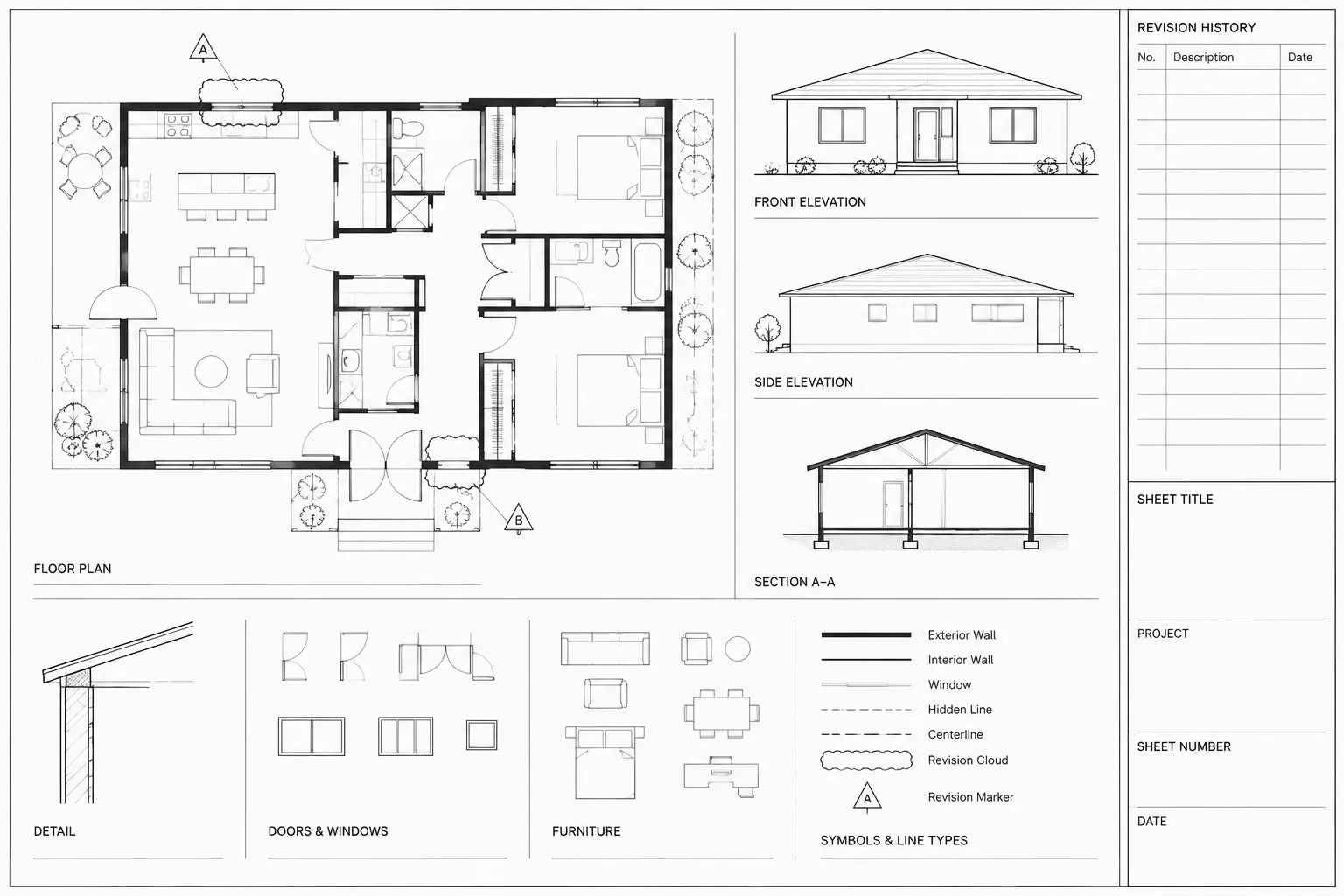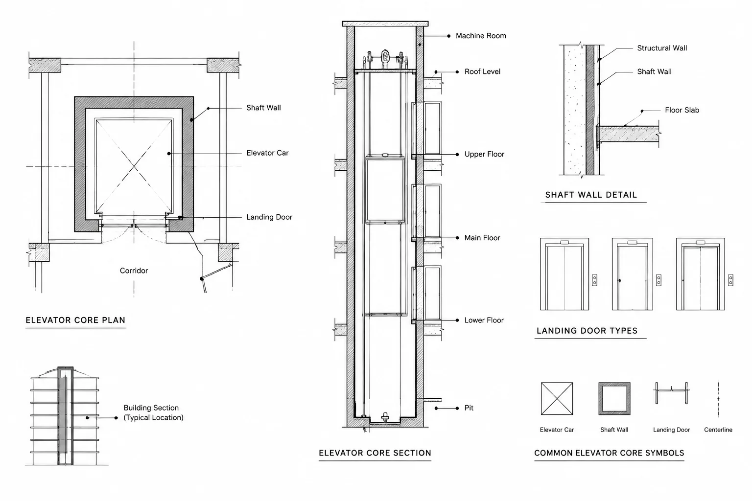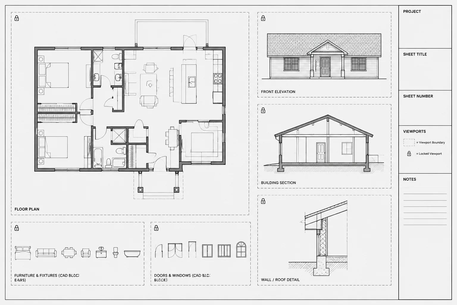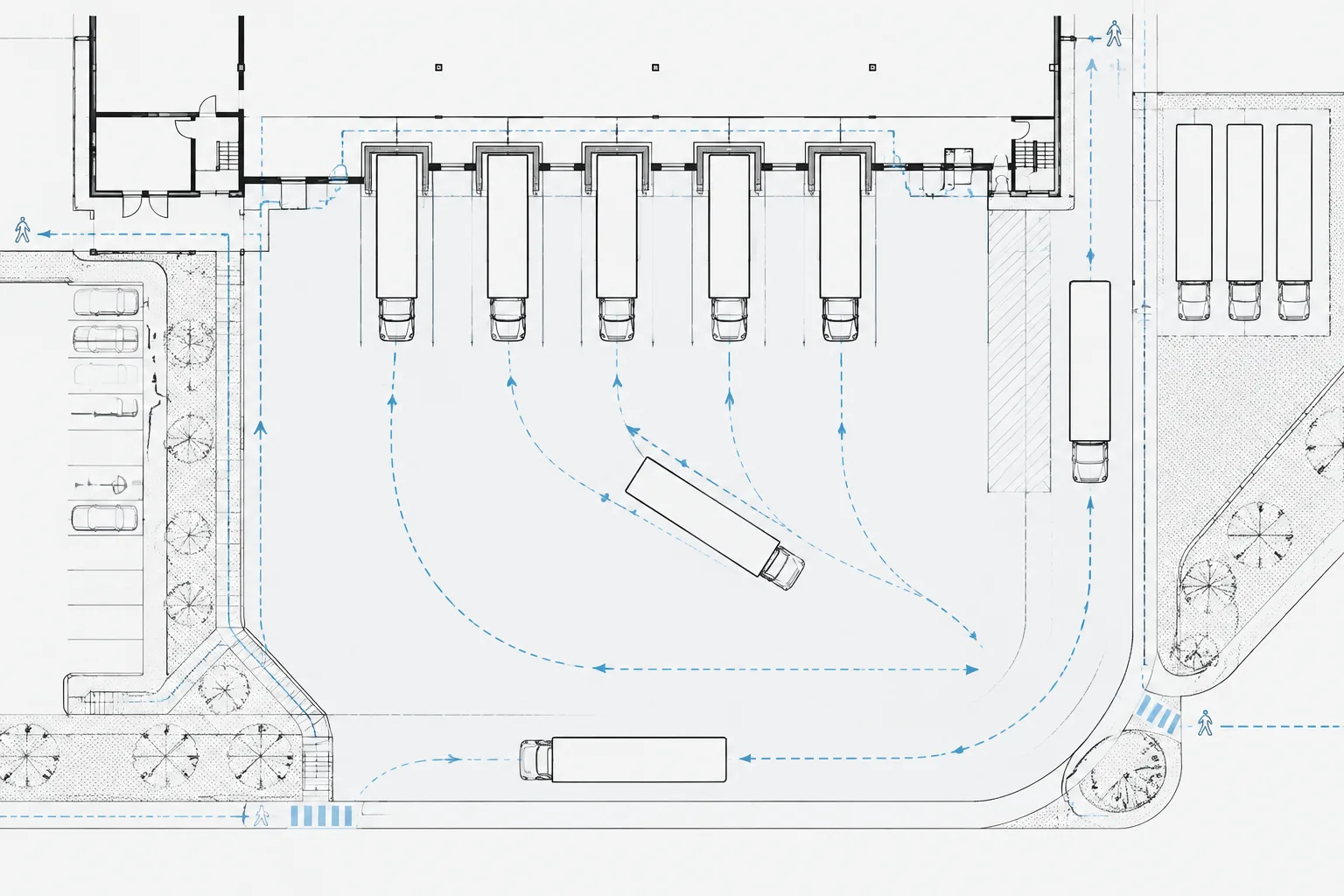
CAD block insertion points determine how reusable drawing content connects to walls, grids, baselines, furniture layouts, and annotation targets. A sensible point makes placement feel direct, while an arbitrary point forces corrective moves and repeated visual checks.
This practical guide is intended for creating block libraries, reviewing downloaded DWG content, and troubleshooting blocks that rotate, align, or replace unpredictably. The key is to choose a working reference based on the placement task rather than relying automatically on the geometric center.
A CAD block can be drawn accurately and still be frustrating to use. One common cause is a poorly selected insertion point. If the base point is far from the visible geometry, located on an arbitrary corner, or inconsistent with similar blocks, placing and replacing the object becomes slower and less reliable.
Well-planned CAD block insertion points support accurate snapping, predictable rotation, easier alignment, and efficient block replacement. The best location depends on what the block represents and how it will be placed in an architectural drawing. A door, plumbing fixture, room tag, and freestanding table should not automatically use the same base-point strategy.
This guide explains how to select practical insertion points, improve existing block libraries, and check blocks before using them in project drawings.
What Is a CAD Block Insertion Point?
A block insertion point is the reference point used to place a block definition in a drawing. When a user inserts the block, the cursor controls this point unless coordinates are entered directly. It also acts as the block’s primary location when the object is moved, rotated, scaled, copied, or referenced through its properties.
The insertion point should normally have a clear relationship to the represented object. It might be a wall intersection, the center of an opening, the back corner of a cabinet, the center of a table, or the tip of a drawing symbol.
This point is not merely a technical requirement. It affects everyday drafting behavior. A logical base point helps users understand where the block belongs without repeatedly zooming in, moving it after insertion, or creating temporary construction geometry.
Start with the Placement Task
Before choosing a base point, ask how the block will be positioned in an actual architectural plan, elevation, section, or detail. The best insertion point is usually the point a drafter needs to snap to existing geometry.
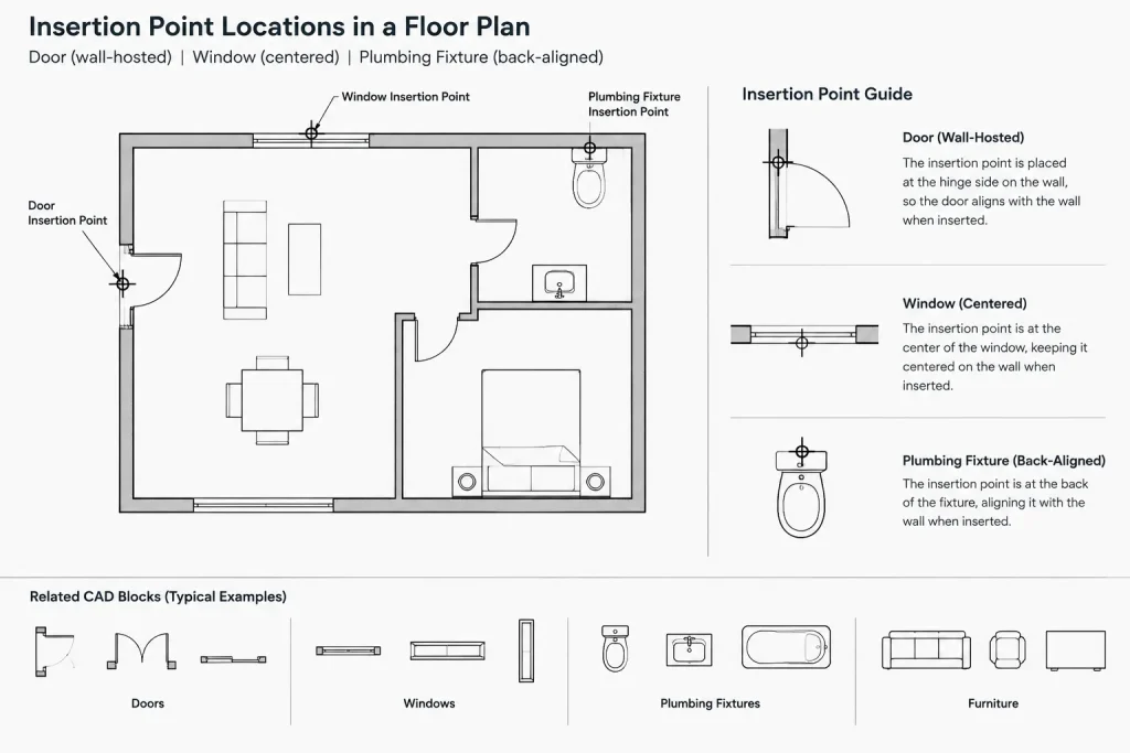
- Wall-hosted objects: Select a point that relates directly to the wall face, opening, centerline, or endpoint used during placement.
- Freestanding objects: Use a meaningful center, corner, or alignment point based on common layout methods.
- Repeated casework: Favor a corner or face that supports end-to-end placement along a run.
- Annotation symbols: Place the base point at the target, center, leader origin, or another visually meaningful location.
- Elevation components: Relate the insertion point to a baseline, centerline, finished surface, or adjacent component edge.
A geometric center is not always the most useful choice. For example, a cabinet is often aligned from its back face or one end rather than from the center of its footprint. The intended drafting operation should guide the decision.
Recommended Strategies by Block Type
Doors and Wall Openings
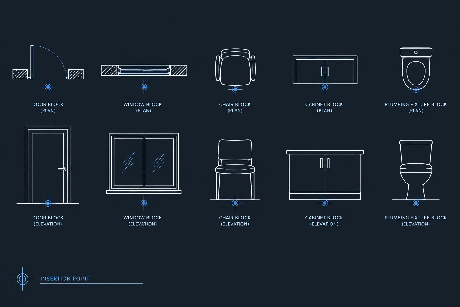
A door block generally benefits from an insertion point located at a jamb or another opening reference that can snap directly to wall geometry. The point should remain logical when the door is rotated or mirrored. If a block includes a panel, frame, and swing, confirm that the base point still represents the intended hinge or jamb relationship rather than a remote point in the swing arc.
Door families should use a consistent convention. Mixing hinge-side, latch-side, opening-center, and frame-corner insertion points within one library makes replacement and rapid placement more difficult.
Windows
Window blocks may be placed from an opening centerline, jamb, wall face, or frame corner, depending on the office workflow and block design. A center-based point can help align windows along a grid or reference line, while a jamb-based point can be more practical when placing openings from dimensioned wall segments.
Plan, elevation, and detail blocks representing the same window type do not necessarily need identical insertion points, but each should follow a documented convention appropriate to its view.
Furniture
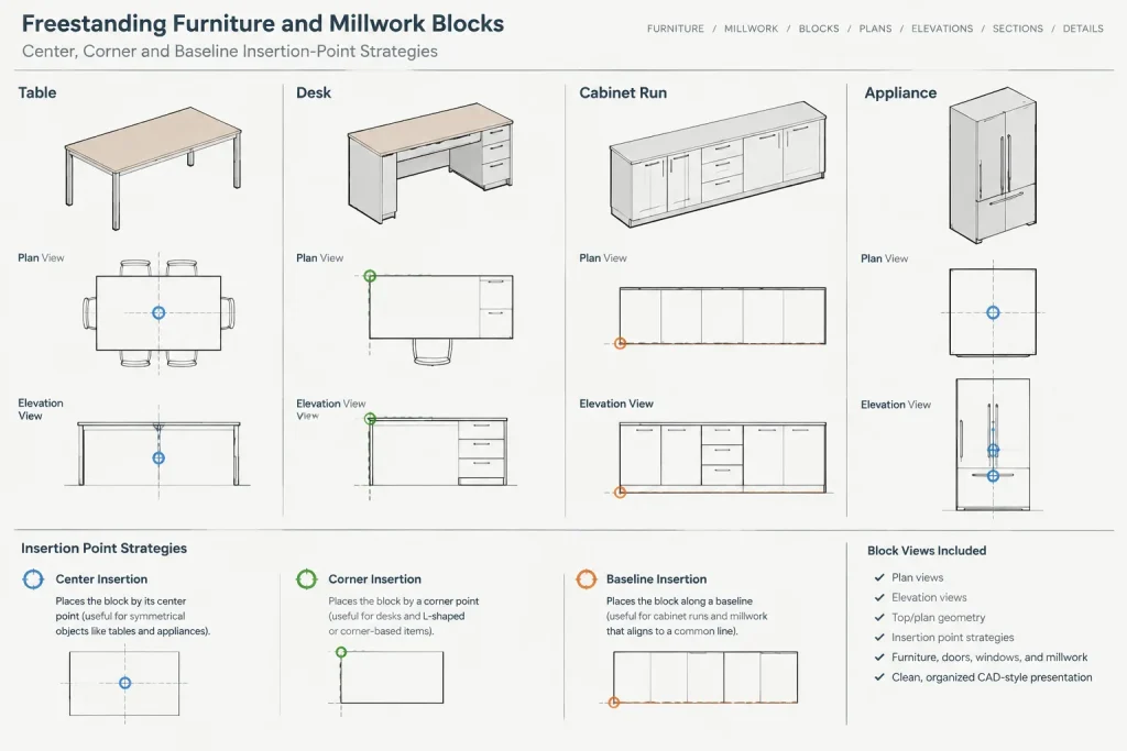
Freestanding furniture often works well with a center or significant corner insertion point. A centered point supports rotation and symmetrical placement, while a corner point supports alignment to room boundaries, adjacent furniture, or planning grids.
Choose according to likely use. A conference table may be arranged around a room centerline, while a desk may be positioned from a back corner or work-surface edge. Avoid using the outer limit of a chair swing, clearance zone, or other optional graphic as the insertion point unless that graphic controls placement.
Plumbing Fixtures and Appliances
Fixtures placed against walls usually need a point on the back face or fixture centerline. This allows the block to snap to a wall and then move laterally into position. A point at the center of the overall bounding box may fall inside the fixture and provide no direct connection to the mounting surface.
If the block includes clearance graphics, keep the insertion point tied to the actual fixture rather than to the clearance boundary. Clearance zones may vary by project criteria, while the fixture location remains the fundamental reference.
Cabinets and Millwork Components
Base cabinets, wall cabinets, shelves, and modular millwork commonly benefit from a back corner insertion point. This supports alignment to wall faces and placement of consecutive units. The chosen side should be consistent across the library so users can predict how every component will insert and rotate.
For elevation blocks, a lower corner or centerline at the installation baseline may be more useful. The point should help align adjacent components without requiring repeated repositioning.
Annotation and Reference Symbols
Symbols should use the point that communicates their drawing function. A section marker may use the end, center, or intersection of its reference geometry. A north arrow may use the center of rotation. A target marker should normally insert at the location being identified.
Do not place the base point at a text corner simply because the text is easy to select. Annotation text may change in length, scale, or orientation, making it an unstable placement reference.
Insertion Point Comparison
| Base-point strategy | Useful for | Potential drawback |
|---|---|---|
| Object center | Rotation, symmetrical layouts, freestanding furniture | May not snap naturally to walls or adjacent objects |
| Back corner | Cabinets, appliances, desks, wall-aligned fixtures | Requires a consistent left-or-right convention |
| Opening centerline | Windows, wall openings, grid-based placement | May be less convenient for endpoint-based dimensions |
| Jamb or hinge point | Doors and operable panels | Mirroring must be tested carefully |
| Target point | Tags, markers, callouts, reference symbols | Text and graphics may extend unevenly around the point |
| Baseline point | Elevations, equipment, millwork, vertical alignment | Depends on a clearly defined drawing datum |
Why Distant Insertion Points Cause Problems
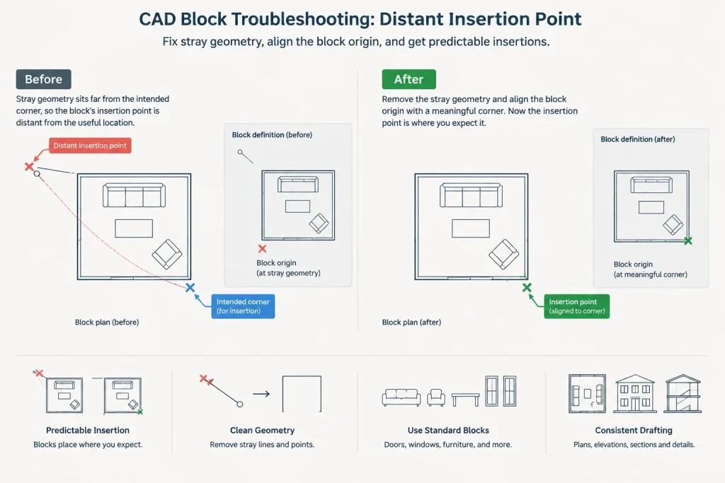
A block may appear to vanish during insertion when its base point is located far from its visible geometry. The cursor follows the insertion point while the actual object remains outside the current view. This often occurs when a block was created from geometry that included an unnoticed stray object or when the selected base point was entered incorrectly.
A remote insertion point can also create unexpectedly large drawing extents, confusing zoom behavior, and difficulty selecting or aligning content. If a downloaded block behaves strangely, inspect both the visible geometry and the location of the block origin before using it in a project.
How to Correct an Existing Block
Before editing a library block, save a controlled copy and check whether the definition is already used in active drawings. Changing a shared definition can reposition every existing instance because the geometry’s relationship to the insertion point has changed.
- Identify the intended placement reference. Decide which point should meet a wall, centerline, grid, corner, baseline, or target.
- Inspect the block definition. Look for stray lines, points, text, hatches, attributes, or invisible construction objects away from the main geometry.
- Relocate geometry deliberately. In the block editing environment, move the component geometry so the desired reference aligns with the block origin.
- Check attributes and parameters. Confirm that editable text, visibility states, actions, and other block behavior still relate correctly to the revised geometry.
- Test a fresh insertion. Insert the revised block into a blank test file rather than judging only an existing instance.
- Test rotation and mirroring. Verify orientation, readable text, swing graphics, and alignment from each expected direction.
- Confirm replacement behavior. If the block is intended to replace another library component, compare their base-point conventions.
Rebuilding a simple block may be safer than modifying a complicated definition with unknown nested content. Preserve any verified data or attributes that must remain attached to the component.
Coordinate Insertion Points Across a Block Library
Consistency is more valuable than selecting a theoretically perfect point for each individual file. Similar components should behave similarly. If all base cabinets insert from the back-left corner, a user can place an entire run without inspecting each definition first.
Create a short library rule for each content category. Document whether doors use the hinge jamb, windows use the opening center, plumbing fixtures use the back-center point, and furniture uses a center or designated corner. The exact rules can vary by office, but they should be easy to understand and test.
Consistent insertion points also improve block substitution. Replacing one chair, fixture, cabinet, or symbol with another is more predictable when both definitions share the same reference logic. Otherwise, the replacement may shift even when its rotation and scale remain unchanged.
Quality-Control Checklist
- The insertion point is located on or near the visible block geometry.
- The point corresponds to a real placement or alignment task.
- Similar blocks use the same base-point convention.
- The block inserts at the expected drawing units and scale.
- Rotation occurs around a useful point.
- Mirroring does not create incorrect text or symbol orientation.
- Clearance graphics do not control the base point unless intentionally required.
- No stray objects distort the block extents.
- Attributes remain legible and correctly positioned.
- Redefining the block will not unexpectedly move approved project content.
A Small Decision with a Large Workflow Impact
CAD block insertion points are easy to overlook because they are usually invisible after placement. However, they influence nearly every interaction with a block, from the first insertion to later rotation, alignment, replacement, and scheduling.
Select each point according to how the represented object is installed, aligned, or referenced in the drawing. Then apply that logic consistently across related content. A predictable block library reduces corrective moves, makes downloaded DWG content easier to evaluate, and helps architectural drawings remain coordinated as they develop.
Applying an Insertion-Point Convention in Practice
A useful office convention should describe both the selected point and the reason for selecting it. Terms such as center or corner can be ambiguous unless the rule also identifies the geometry being referenced, such as the opening, frame, back face, mounting edge, or annotation target.
When similar objects require different placement methods, consider maintaining clearly identified variants rather than forcing one block to support conflicting workflows. For example, content intended for wall alignment may need different reference logic from content intended for grid-based space planning. The block name, preview, or library description should make that distinction understandable.
Diagnosing Insertion-Point Problems
- The geometry appears far from the cursor: Inspect the definition origin, nested content, and stray objects beyond the visible component.
- Rotation feels awkward: Check whether the block is rotating around a useful physical or layout reference.
- Replacement causes a shift: Compare the insertion-point conventions of the original and replacement definitions.
- Every placement requires a follow-up move: The selected point probably does not match the drafter’s usual snap target.
- Drawing extents seem unexpectedly large: Look for remote geometry, attributes, points, or nested elements as well as a misplaced base point.
Review the Entire Definition
The visible outline is only part of a block. Attributes, wipeouts, hatches, nested blocks, construction objects, and optional graphics can affect editing and extents. Review these elements before relocating geometry around the block origin.
Perform revisions in a controlled test file and compare fresh insertions with existing content. This separates a definition problem from an issue caused by a particular block reference, drawing environment, or previous edit. Once the behavior is verified, document the convention so future library additions follow the same placement logic.
Frequently Asked Questions
Should every CAD block use its geometric center as the insertion point?
No. The geometric center is useful for some freestanding or symmetrical objects, but wall-mounted objects, openings, cabinets, and reference symbols often need a point tied to an edge, jamb, centerline, baseline, or target.
Why does a block appear far away from the cursor during insertion?
The block origin may be remote from its visible geometry, or the definition may contain a stray or nested object that affects its extents. Inspect the complete definition rather than moving the inserted reference without investigating the cause.
Can changing a block insertion point affect existing instances?
Yes. Moving geometry relative to the definition origin can change where existing references appear. Work on a controlled copy and test the revised definition before updating content used in active drawings.
Is an insertion point the same as an object snap point?
Not exactly. The insertion point is the primary reference used to place the block. Object snaps can also locate endpoints, midpoints, centers, intersections, and other points on geometry within the block, depending on the drawing setup and available geometry.
Why do blocks shift when one definition is replaced with another?
The definitions may use different reference conventions. Even when their visible geometry is similar, a center-based block and a corner-based block will not occupy the same position when substituted directly.
Should clearance graphics determine the base point?
Usually the insertion point should remain tied to the represented object or its installation reference. Optional clearance graphics should control placement only when the library is intentionally designed around that workflow.