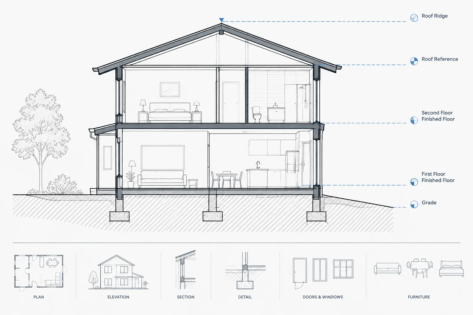
Floor levels connect nearly every part of an architectural drawing set. They establish where floors, ceilings, roofs, openings, landings, and site features sit vertically. When level information is inconsistent, a floor plan may appear correct by itself while conflicting with sections, elevations, stairs, or consultant drawings.
A reliable CAD workflow treats levels as coordinated project information rather than isolated text labels. The goal is to create a clear vertical reference system, use it consistently, and make changes without leaving contradictory values elsewhere in the drawing set.
Understand the different types of vertical reference
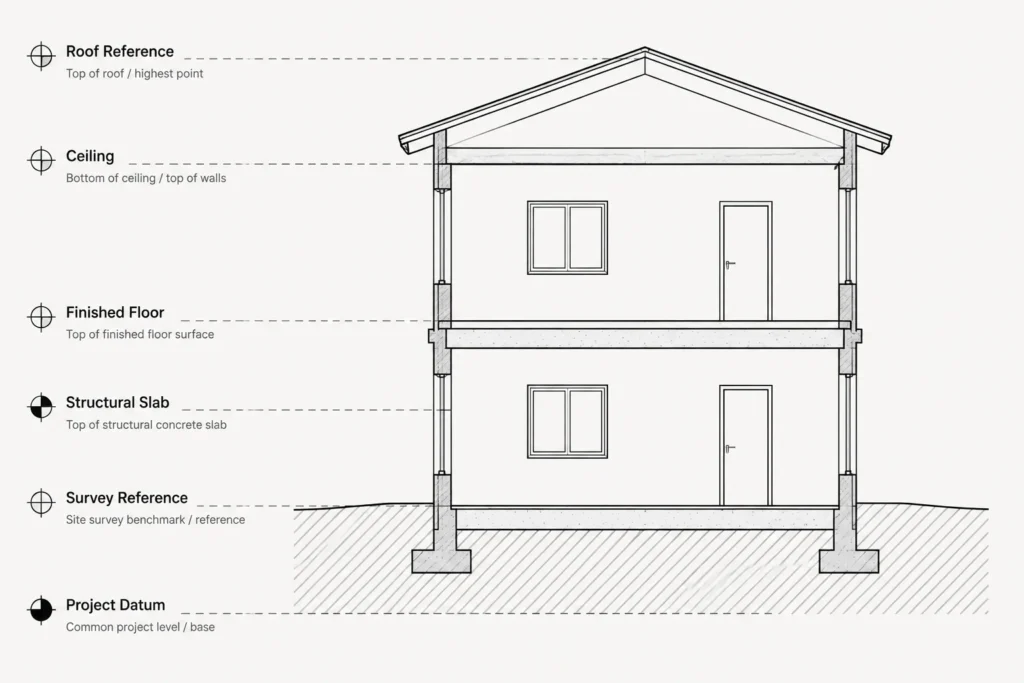
Before drafting level markers, identify what each elevation value represents. Similar-looking labels can refer to different physical surfaces or reference systems.
Project datum
A project datum is an agreed reference from which building elevations are measured. A team may use a simplified project elevation system for architectural coordination. The selected reference should be documented so that everyone understands its meaning.
Survey or civil datum
Site and civil information may use elevations tied to a surveyed benchmark or another established vertical reference. Do not assume that a project datum and a survey datum are interchangeable. If both appear in the drawing set, clearly document their relationship using verified project information.
Finished floor level
A finished floor level generally identifies the elevation of the completed walking surface. This is different from the top of structural framing, top of slab, or top of subfloor. The distinction becomes important when finish build-ups, depressed slabs, raised floors, or transitions occur.
Structural and construction levels
Consultants may reference structural slabs, framing members, foundations, or other construction surfaces. Architectural drawings should not relabel these as finished levels unless the surfaces are actually intended to coincide.
Ceiling, roof, and site elevations
Ceiling heights, parapets, roof edges, ridges, canopies, grade points, and paving surfaces may also require elevation information. These should be identified by what the marker measures, not merely by a number placed near the object.
Create a level register before extensive annotation
A small working register helps the CAD team organize vertical information before placing numerous level symbols. It can be maintained as an internal coordination table or incorporated into project documentation when appropriate.
| Level reference | Physical surface or point | Primary drawing locations | Coordination concern |
|---|---|---|---|
| Floor level | Verified finished floor or construction surface | Plans, sections, elevations | Confirm which surface the value describes |
| Landing level | Stair or ramp landing surface | Plans and sections | Coordinate with connected floors and circulation geometry |
| Ceiling level | Finished ceiling plane or designated ceiling feature | Reflected ceiling plans, sections, interior elevations | Distinguish continuous ceilings from local changes |
| Roof level | Specified roof plane, edge, ridge, or parapet reference | Roof plans, elevations, sections | Account for slope and identify the measured point |
| Exterior grade | Existing or proposed ground and paving surfaces | Site plans, elevations, sections | Distinguish existing conditions from proposed work |
The register should describe level intent rather than becoming an unverified source of values. Actual elevations must come from coordinated project information.
Establish one controlled source for level information
Repeated level values are vulnerable to editing errors. Decide where the working level information will be controlled and who is responsible for updating it. Depending on the project structure, that source may be a designated base drawing, a shared reference file, or a formally maintained project table.
Referenced geometry can help align plans, sections, and elevations, but references alone do not guarantee correct annotations. A copied level marker may remain visually aligned while containing outdated text. Both geometry and displayed values require checking.
A practical rule is to avoid typing the same value independently in many unrelated files. When repetition is necessary, include level verification in the drawing review process.
Draft level markers for unambiguous reading
A useful level marker communicates three things: the location being measured, the type of surface or feature, and the associated elevation. Graphic style should be consistent across the set without overpowering the building drawing.
- Place the marker head and leader so the measured point is visually clear.
- Use concise labels that distinguish finished floor, slab, grade, roof, ceiling, and other references.
- Keep marker orientation consistent within each drawing type.
- Separate overlapping markers rather than stacking text into an unreadable cluster.
- Use annotation layers that plot clearly and can be managed independently from model geometry.
- Avoid using a generic marker where the measured surface is uncertain.
In elevations and sections, a horizontal extension from the marker can help associate the value with a floor or datum line. That line should not imply that a level continues through an area where the surface actually steps or slopes.
Coordinate levels across drawing types
Floor plans
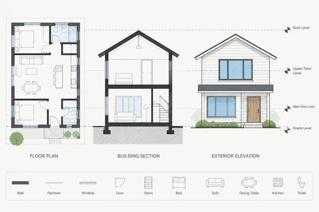
Plans commonly identify the level of the floor being shown and local changes within it. Mark depressed areas, platforms, landings, exterior paving, and other verified changes where they affect interpretation. Do not fill the plan with redundant markers if one clear note and several targeted change indicators communicate the information better.
Building sections
Sections are the primary place to test vertical relationships. Align floor surfaces, ceiling planes, roof geometry, openings, and foundations against the established datum system. A section should reveal whether level transitions shown in plan can actually connect as intended.
Exterior elevations
Elevation markers should correspond to the same physical references used in sections. Check floor lines against window heads, door openings, canopies, parapets, grade, and adjacent site surfaces. Be careful with sloping grade: one grade marker cannot describe an entire facade when the ground changes along it.
Interior elevations and enlarged drawings
Interior elevations often use local vertical dimensions for cabinets, fixtures, finishes, and ceiling features. Relate these dimensions to the correct floor reference. If the room contains a step, platform, or floor transition, identify which floor surface controls each vertical measurement.
Stairs and ramps
Stair and ramp drawings depend on verified start and end levels. Coordinate the plan geometry with sections and enlarged details whenever connected levels change. CAD blocks representing stairs or ramps should be treated as graphic starting points, not proof that the vertical transition works.
Handle split levels, slopes, and local depressions carefully
Not every floor is a single horizontal plane. Split-level buildings, sloped floors, recessed showers, equipment pads, loading areas, terraces, and drainage surfaces require more specific annotation.
For stepped conditions, label each relevant horizontal surface and show the transition in section. For sloped surfaces, identify the high and low relationships or other controlling points using verified project data. A single central marker can falsely suggest that the entire area is level.
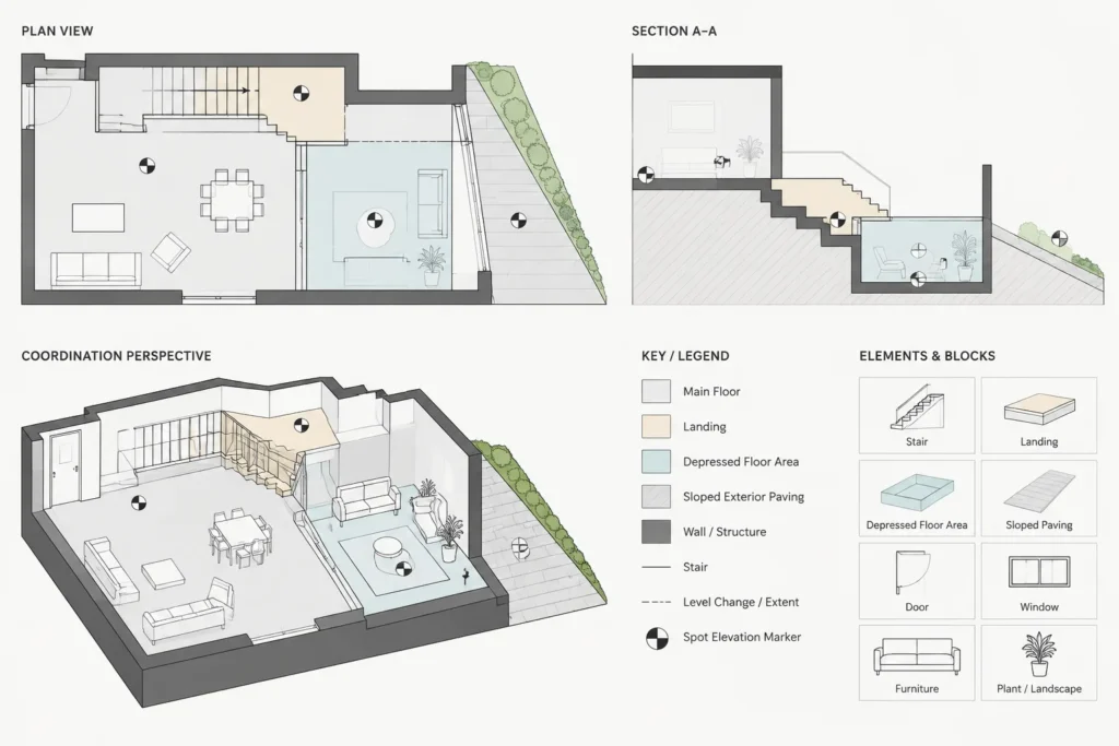
Use break lines, slope indicators, spot elevations, and section references where appropriate to explain the geometry. The exact annotation method should follow the project’s drafting conventions and the information available.
Separate model geometry from annotation
Organize level symbols, datum lines, text, and related dimensions on predictable annotation layers. Building geometry should remain on its appropriate object layers. This separation makes it easier to control visibility, plotting, and drawing-specific notes without hiding essential model elements.
If level markers are built as reusable blocks, use a consistent insertion point tied to the measured location. Keep optional graphics manageable, and avoid embedding project-specific values in a generic library block. Before using an external block, inspect its units, layers, text style, attributes, and insertion point.
Use a repeatable level-coordination review
Perform a vertical coordination review whenever floor assemblies, site elevations, structural depths, ceiling zones, roof forms, or circulation layouts change.
- Confirm that every displayed elevation uses the intended datum.
- Verify that each value refers to a clearly identified physical surface.
- Compare corresponding floor lines in plans, sections, and elevations.
- Check stairs, ramps, landings, and thresholds against connected levels.
- Review exterior doors and accessible routes with the responsible project team where elevation transitions occur.
- Compare architectural levels with current structural, civil, and other consultant information.
- Search for old text, duplicated markers, and annotations located outside active drawing areas.
- Plot or preview sheets to check marker readability and overlaps at the intended presentation scale.
Do not resolve a discrepancy by changing one drawing merely to make the numbers look consistent. Determine which source is current, confirm the intended condition, and then update every affected view.
Common level-drafting mistakes
- Mixing datums without explanation: Survey and project elevations appear together with no documented relationship.
- Confusing finish and structure: A marker does not state whether it refers to finish, slab, framing, or another surface.
- Editing only one view: A plan is updated while sections and elevations retain earlier information.
- Using floating text: The elevation value is placed near an object without a clear measured point.
- Overlooking local changes: Depressions, platforms, and sloped areas are represented as one continuous level.
- Trusting downloaded content: A stair, ramp, fixture, or site block is assumed to contain suitable geometry or elevation data without verification.
Build vertical coordination into the CAD workflow
Level coordination is most effective when it begins with the drawing setup rather than at final checking. Establish the datum, define what each level represents, organize the information in a controlled location, and use consistent markers throughout the project.
As the design develops, review levels as connected relationships rather than isolated numbers. A floor elevation affects stairs, openings, ceilings, roofs, facade composition, and site transitions. Keeping those relationships visible in the CAD workflow produces drawings that are easier to read, revise, and coordinate.