
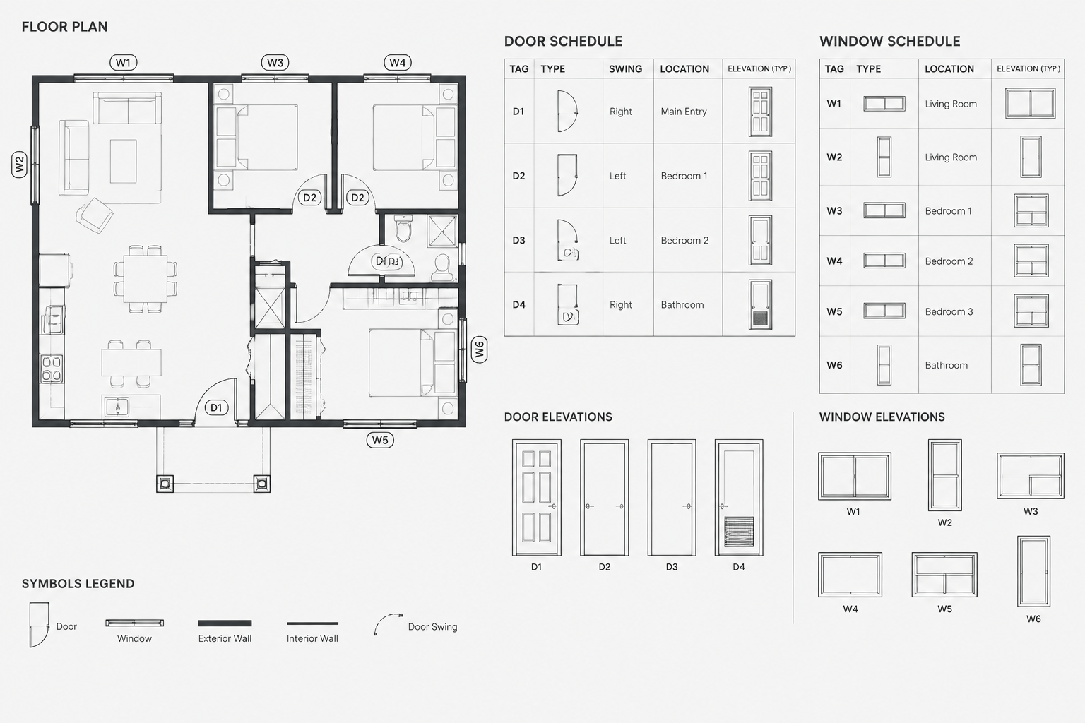
Door and window schedules turn repeated drawing information into an organized project reference. Their value, however, depends on coordination. A schedule can look complete while still disagreeing with the floor plan, elevation, or detail where an opening appears.
A reliable door and window schedule CAD workflow begins with consistent opening types, identifiers, blocks, and annotation. It also requires a deliberate checking process whenever the design changes. The objective is not simply to populate a table. It is to make every tagged opening traceable across the drawing set.
What a Door or Window Schedule Represents
A schedule is a structured index of openings shown elsewhere in the project drawings. Depending on the project, it may identify opening types, materials, operation, glazing, hardware references, frame information, remarks, or related details. The required fields should be established by the project team rather than copied automatically from an unrelated template.
The distinction between an individual opening and an opening type is important. An individual identifier refers to a particular location in the building. A type designation groups openings that share defined characteristics. Some drawing sets schedule every opening individually, while others use type marks alongside separate type elevations. Either method can work when it is applied consistently and communicates the necessary information.
Establish the Information Structure Before Tagging
Before placing tags, decide what each identifier means and which drawing element is responsible for carrying it. An opening tag should not alternate unpredictably between representing a panel, a complete assembly, a frame, or a type.
Create a short project convention covering:
- How individual doors and windows are identified
- How repeated types are named
- Whether identifiers are unique across the project or reset by floor, area, or building
- Which schedule fields are required
- How demolition, existing, relocated, and new openings are distinguished
- Where elevations, sections, and details are referenced
- Who is responsible for updating and checking the schedule
This convention does not need to be lengthy. A concise note in the project CAD manual or drawing checklist can prevent multiple drafting interpretations later.
Build Consistent Door and Window Blocks
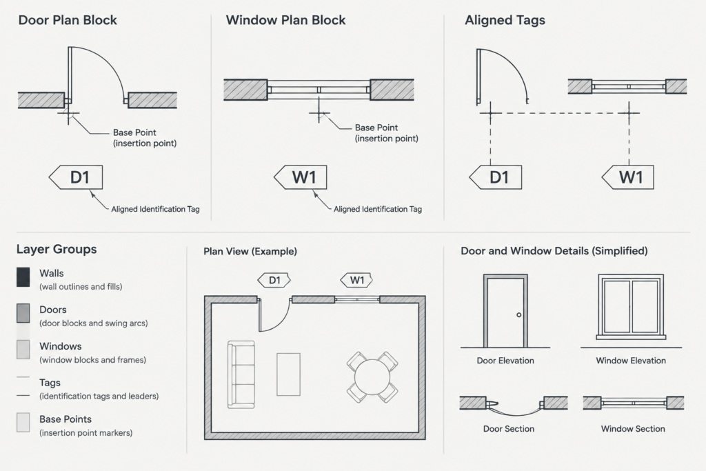
Opening graphics should be easy to edit without losing their identity. Door blocks commonly include the leaf and swing in plan, while window blocks may show the frame and glazing relationship appropriate to the plan’s level of detail. Wall openings, jamb lines, overhead elements, and sill conditions may need separate control depending on the drawing scale and office workflow.
Use a consistent base point so blocks insert and replace predictably. For doors, a hinge or jamb reference is often more useful than an arbitrary point outside the geometry. For windows, a centerline or defined frame reference may support alignment. The best base point is the one that remains meaningful during design revisions.
Do not overload a single block with every possible construction condition. Highly complex blocks can become difficult to audit. Separate block families or clearly managed visibility states may be more practical when opening configurations differ substantially. Whatever method is selected, test mirrored instances carefully. Text, tag orientation, handing indicators, and asymmetric geometry can behave differently after mirroring.
Use attributes only for information they can manage reliably
Block attributes can store identifiers and other short data fields. They are useful when the information belongs to the placed object and must remain attached as it moves. Attributes are less effective when users also maintain an unrelated text label or schedule entry manually. Duplicate sources create uncertainty about which value is current.
If attributes will support data extraction, keep field names stable and avoid using visually similar attributes for different purposes. A field called Type should not mean the assembly type in one block and the operation type in another.
Place Tags for Reading and Coordination
Tags should be legible at the intended sheet scale and should not obscure walls, dimensions, room names, or other critical notes. Place them according to a repeatable graphic convention. Door tags may sit near the opening or within the room served, while window tags may be positioned beside the wall or linked with a leader where the plan is crowded.
Tag placement must also make ownership clear. At paired doors, closely spaced windows, storefront systems, and grouped openings, a reader should be able to identify exactly which assembly a mark describes. Leaders can resolve ambiguity, but excessive crossing leaders usually indicate that the annotation layout needs further organization.
Keep tags on dedicated annotation layers rather than combining them with opening geometry. Separate layers make it easier to control display in plans prepared for different purposes. A coordination plan may require all marks, while a presentation plan may suppress schedule tags.
Choose Schedule Fields Deliberately
A schedule should contain information that helps the drawing set communicate, coordinate, or specify the opening. Adding columns merely because they exist in a template can produce empty cells and conflicting notes.
| Field category | Coordination purpose | Common drafting concern |
|---|---|---|
| Identifier | Connects the schedule row to the plan tag | Duplicate, missing, or obsolete marks |
| Type | Links an opening to a repeated configuration or elevation | Type changed in plan but not in the schedule |
| Location | Helps reviewers find the opening | Room names revised without updating the row |
| Size information | Records the project-defined opening or component dimensions | Unclear whether values describe rough openings, frames, or panels |
| Material or finish | Coordinates architectural intent | Terminology differs from notes or specifications |
| Operation or handing | Describes how the unit functions | Plan swing conflicts with the listed condition |
| Detail reference | Directs the reader to related construction information | Reference points to a removed or renumbered detail |
| Remarks | Records an exception that does not fit another field | Important requirements buried in inconsistent free text |
Schedule headings should define ambiguous measurements. For example, do not assume that every reader interprets Width or Height as the same part of an assembly. State the intended basis through the heading, a schedule note, or the project’s documented convention.
Coordinate Plans, Elevations, Sections, and Details
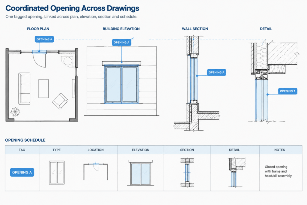
The floor plan usually establishes location, orientation, and relationship to rooms. Elevations communicate composition, alignment, head and sill relationships, and visual grouping. Sections and details explain how the assembly relates to walls, floors, finishes, and adjacent construction. The schedule organizes selected properties. None of these views should be treated as an isolated source.
When checking a door, compare the plan swing with the scheduled operation or handing. Confirm that the opening identifier is unique and that any type elevation shows the same configuration. Review wall thickness, jamb conditions, and nearby clearances as project-specific coordination items without assuming that a generic CAD block resolves them.
For windows, compare the plan location with exterior and interior elevations. Look for missing units, inconsistent divisions, alignment changes, and windows concealed by annotation. Where a window continues across multiple spaces or forms part of a larger glazed assembly, determine whether it is scheduled as one system or several units and show that decision consistently.
Use a Controlled Revision Workflow
Opening schedules often become inaccurate during revisions because plan graphics are edited first and schedule review is postponed. Treat every opening change as a linked set of tasks.
- Revise the opening geometry and wall opening.
- Confirm the block or object still carries the correct identifier.
- Update the related schedule row or extracted data.
- Check elevations, sections, and detail references.
- Review dimensions and nearby annotation affected by the change.
- Remove abandoned tags, rows, leaders, and type drawings.
- Record the change according to the project’s revision procedure.
If the schedule is generated from block data, extraction reduces repetitive entry but does not replace review. A correctly extracted attribute can still contain incorrect information. If the schedule is drafted manually, use a comparison checklist and assign responsibility for reconciling it with the latest plan.
Run Visual and Data-Based Quality Checks
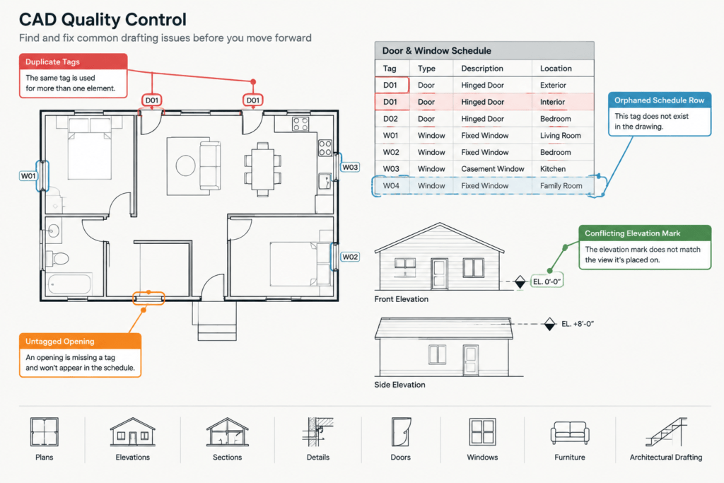
A final review should include both drawing inspection and identifier auditing. Visually trace tags through the plan in a consistent order, such as by floor and room sequence. Then compare the resulting list with the schedule.
Look specifically for duplicate identifiers, skipped marks, schedule rows without plan tags, tags without schedule rows, blank required fields, inconsistent type names, mirrored handing errors, and references to deleted details. Also search model space for opening blocks outside the active building plan. Design alternatives, copied layouts, and archived geometry can contaminate extracted schedules if they remain selectable.
Plot or preview the relevant sheets before issue. Layer states, annotation scales, viewport clipping, and dense linework can make a tag unreadable even when it appears correct while editing. A schedule is coordinated only when the information is accurate and the intended reader can find it.
Treat Downloaded DWG Blocks as Starting Geometry
Downloaded door and window blocks can accelerate drafting, but they should be inspected before entering the project library. Check units, insertion points, layers, linework, text, attributes, naming, and behavior when mirrored or scaled. Remove unnecessary nested content and verify that the graphic convention matches the office drawing set.
A library symbol does not establish code compliance, product availability, rough-opening requirements, structural support, fire performance, accessibility, or suitability for a particular wall assembly. Those conditions require project-specific verification. The CAD block’s role is to communicate verified design information clearly, not to substitute for that verification.
A well-managed door and window schedule CAD workflow makes changes visible and traceable. Consistent identifiers, disciplined blocks, purposeful schedule fields, and repeated cross-checking help the plans, elevations, details, and schedules function as one coordinated set rather than separate drawings.




