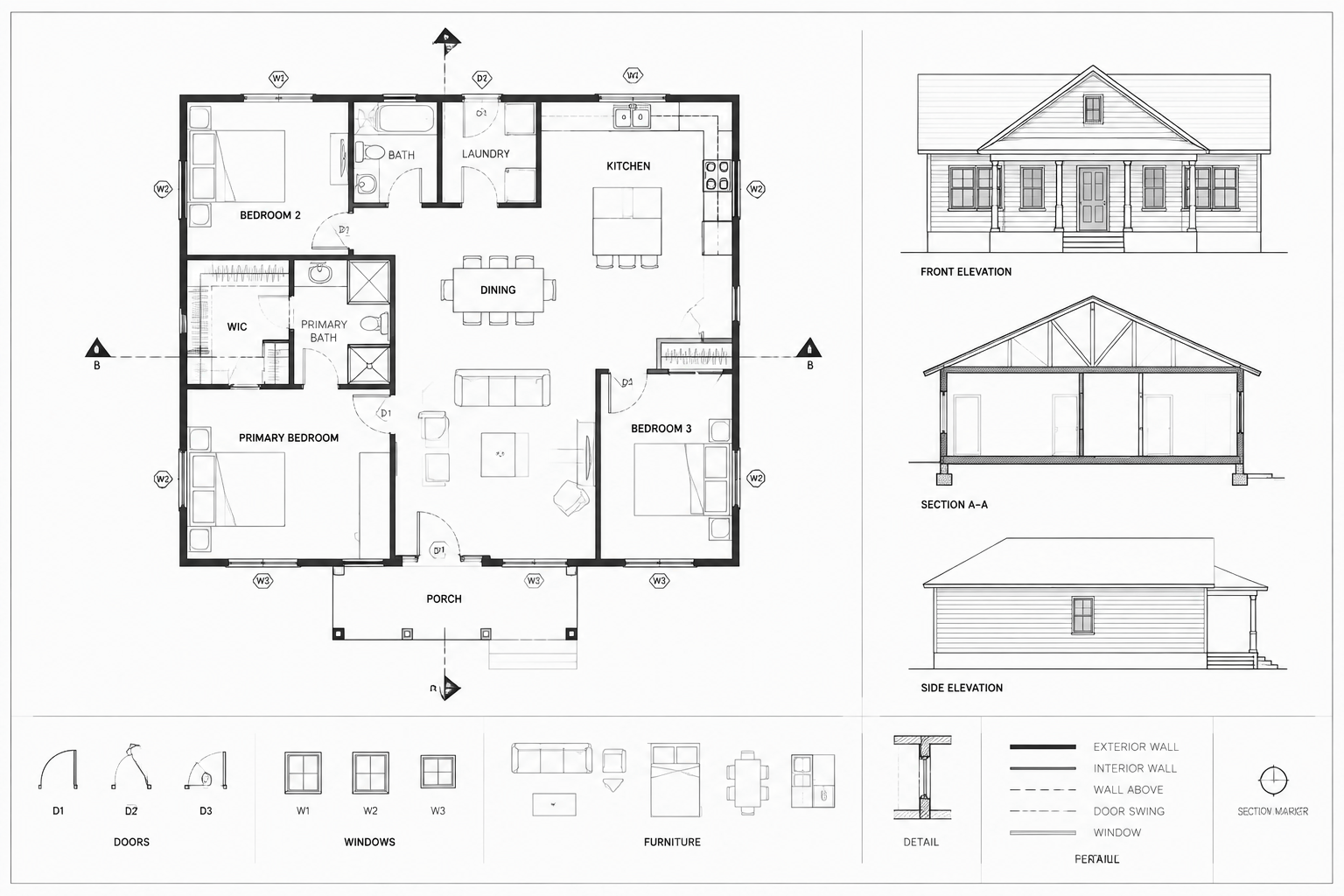
A floor plan can be geometrically accurate and still be difficult to use. Walls, doors, windows, fixtures, and furniture describe the building, but annotation explains how the drawing should be read. Room names establish spatial use, dimensions communicate measured relationships, tags connect objects to schedules, and reference symbols direct readers to related views.
Effective architectural floor plan annotation is not simply a matter of adding more text. The goal is to present the necessary information with a clear hierarchy while avoiding duplication, conflicts, and visual clutter. The following workflow can be adapted to small residential drawings, commercial plans, tenant layouts, and larger coordinated drawing sets.
Begin with a Clean and Coordinated Plan
Annotation should follow a reasonably stable drawing base. If walls are still moving, openings are uncoordinated, or room layouts are incomplete, dimensions and tags will require repeated editing. Before annotating, review the plan for overlapping objects, duplicate linework, disconnected wall intersections, misplaced blocks, and inconsistent layers.
Confirm which information belongs in the current plan. A general floor plan may need room identification, primary dimensions, door and window references, section markers, and key notes. A finish plan, furniture plan, life-safety plan, or equipment plan may require a different annotation strategy. Trying to display every project requirement on one plan usually reduces readability.
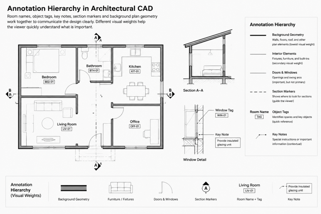
Establish an Annotation Hierarchy
Not every note should have the same visual emphasis. A reader should be able to identify the drawing title, major spaces, dimensions, object tags, and supporting notes without searching through a uniform field of text.
A practical hierarchy can distinguish between:
- Primary identifiers: room names, major plan zones, and prominent view references.
- Measured information: dimension strings, levels, coordinates, and other location controls.
- Object references: door tags, window tags, wall-type tags, equipment labels, and fixture identifiers.
- Supporting information: key notes, local instructions, material transitions, and installation-related notes.
- Context information: existing features, overhead elements, adjacent spaces, and background references.
Hierarchy can be created through text size, lineweight, framing shapes, placement, and spacing. Color may help while drafting, but the plotted sheet must remain understandable using its intended output settings.
Separate Annotation by Function
Place annotation on managed layers rather than mixing it with walls, furniture, or imported references. A project may separate dimensions, room text, door tags, window tags, key notes, section references, and revision information. The exact layer names should follow the office or project convention, but each layer should have an identifiable purpose.
Functional separation makes it easier to control visibility in different viewports. For example, furniture labels may be useful on a furniture plan but unnecessary on a general construction plan. It also allows annotation to be reviewed, frozen, or isolated without disturbing the building geometry.
Set Up Text and Dimension Styles Before Placement
Choose approved text and dimension styles before annotating the sheet. Consistent styles reduce manual formatting and make future changes easier. Review the font, plotted text height, width behavior, arrowheads, dimension precision, unit display, extension lines, and spacing conventions required for the project.
Decide whether annotation will be scaled through annotative objects, viewport-specific methods, or another established office workflow. Avoid compensating for scale by manually resizing individual notes. Mixed methods can produce inconsistent plotted results and make later sheet-scale changes difficult.
Test the setup in a representative layout and plot preview. Annotation that appears comfortable in model space may become crowded or too light when viewed on the final sheet.
Place Room Names and Space Identifiers
Room names should be easy to find without obscuring plan geometry. Place them in open areas when possible, using consistent alignment throughout the drawing. If room numbers are required, keep their relationship to the room name consistent.
Small or irregular spaces may not have enough room for internal text. In those cases, use a coordinated leader, keyed identifier, or another project-approved method rather than forcing text across walls and fixtures. Avoid using furniture as the visual center of a room label because furniture layouts may change independently of room boundaries.
Room names must match schedules, finish information, and related plans. Similar labels should be reviewed carefully so that abbreviated and full names do not accidentally describe the same space in conflicting ways.
Build Dimensions from the Building Outward
Dimensions should explain size and location rather than trace every visible edge. Begin by determining which elements control construction or coordination. These may include structural grids, wall faces or centerlines, openings, major partitions, equipment locations, and overall extents.
Organize dimension strings so the reader can move from detailed information near the plan to broader information farther away. Keep strings aligned where practical, provide space between text and nearby graphics, and avoid crossing leaders, symbols, and extension lines.
Avoid Redundant Dimensions
Repeated dimensions can become contradictory when one value changes and another is missed. Include a dimension where it is most useful and coordinate dependent information through the drawing set. Do not assume that automatically measured geometry is suitable for issue; verify the intended reference points, rounding, units, and displayed values.
Do Not Use Dimensions to Repair Uncertain Geometry
A dimension should report coordinated geometry, not hide an unresolved condition. If a wall, opening, or block is inaccurately placed, correct the model or drawing base before adjusting dimension text. Manual text overrides can conceal errors and should be used only when the project workflow specifically requires them and the result remains truthful.
Coordinate Tags with Schedules
Door, window, wall-type, finish, fixture, and equipment tags act as references to information elsewhere in the set. Their value depends on coordination. A tag that does not match its schedule creates ambiguity even if it is graphically attractive.
Use a repeatable placement rule. Door tags, for example, should be positioned so readers can associate each tag with the correct opening without following tangled leaders. When several tagged objects are close together, move tags into clear space and use restrained leaders rather than stacking symbols over the geometry.
| Annotation type | Primary purpose | Coordination check |
|---|---|---|
| Room identifier | Names or indexes a space | Match room, finish, and area information |
| Door or window tag | Connects an opening to a schedule | Check identifier, type, and opening association |
| Wall-type tag | References an assembly designation | Confirm the leader points to the intended wall |
| Section or elevation marker | Directs readers to another view | Verify view direction and sheet reference |
| Key note | Links a local condition to a note list | Remove unused notes and duplicate identifiers |
Use Notes and Leaders Selectively
Notes are most effective when they address a condition that cannot be communicated clearly through geometry, tags, or standard symbols. Keep note language concise and specific. Broad instructions that apply throughout the project may belong in general notes, while a unique local condition may need a leadered note at the relevant location.
Leaders should terminate unambiguously. Point them to the actual object, surface, or boundary being described rather than to empty space nearby. Keep leader paths simple, avoid unnecessary bends, and prevent arrowheads from merging with dense linework.
Coordinate References to Elevations, Sections, and Details
Reference markers turn an individual plan into part of a coordinated drawing set. Before issue, verify that each section line, elevation marker, and detail callout refers to an existing destination. Confirm that the viewing direction matches the intended view and that renamed or relocated sheets have not left outdated references behind.
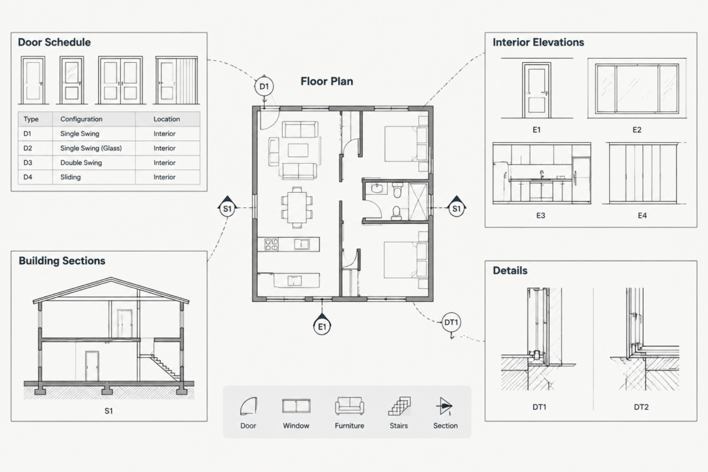
Place markers where they explain the drawing without covering important plan information. If a marker must be offset, retain a clear visual relationship between the symbol and the area or cut being referenced.
Resolve Annotation Collisions
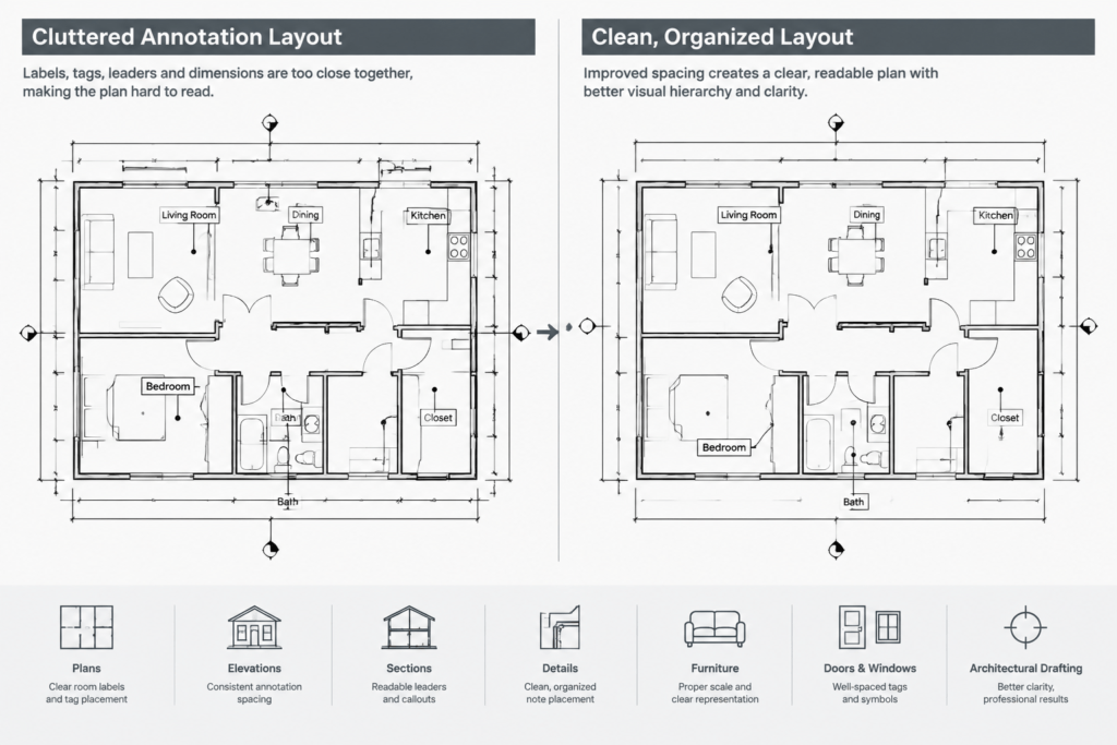
Annotation often accumulates in corridors, restroom groups, kitchens, entrances, and other compact areas. Do not solve every collision by shrinking text. Instead, review whether information can be moved, aligned, consolidated, or assigned to a more appropriate plan.
- Move notes into open areas and use clear leaders.
- Align related tags to create an orderly reading pattern.
- Break or relocate dimension strings that obscure symbols.
- Use enlarged plans for areas that cannot be documented clearly at the primary scale.
- Remove duplicate information that is already communicated elsewhere.
- Control background visibility so secondary graphics do not compete with annotation.
Perform a Sheet-Based Quality Check
Review annotation from the layout or plotted sheet, not only from a close model-space view. Check every viewport at its assigned scale and confirm that text remains legible, symbols are recognizable, and linework does not pass through labels.
A focused review should include spelling, room-name consistency, duplicated identifiers, empty tags, broken leaders, incorrect references, dimension overrides, missing dimensions, and annotation placed on the wrong layer. Also inspect viewport boundaries and clipped areas to ensure required notes have not been hidden.
Finally, compare the plan with schedules and related drawings. Door tags should agree with the door schedule, room identifiers should align with finish information, and section references should lead to the correct views. Any downloaded CAD block or symbol should be checked for scale, layers, attributes, graphic quality, and suitability before it is incorporated into project documentation.
A Repeatable Annotation Sequence
A consistent order helps reduce rework: stabilize the plan base, establish styles and layers, place room identifiers, add object tags, locate view references, build dimensions, add necessary notes, resolve collisions, and review the plotted sheet. The process should finish with cross-drawing coordination rather than a purely visual check.
Clear annotation allows a floor plan to function as a communication document rather than a collection of CAD entities. When text, dimensions, tags, and references follow a deliberate hierarchy, the drawing becomes easier to review, coordinate, revise, and use.