Architectural wall poche gives cut walls visual weight so rooms, circulation, openings, and building edges can be understood quickly. In CAD, however, the quality of the result depends as much on boundary geometry, layer control, and plotting as it does on the selected fill.
This guide presents a maintainable architectural wall poche CAD workflow for floor plans. It explains how to choose a graphic strategy, prepare wall geometry, coordinate openings and renovation conditions, manage referenced drawings, and verify the final sheet without treating poche as a substitute for accurate drafting.
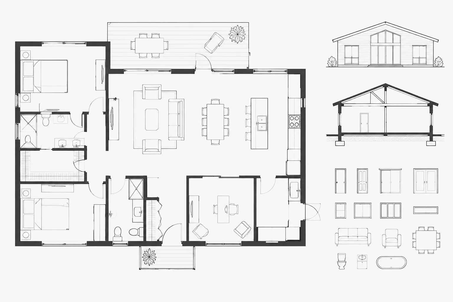
Wall poche is the graphic treatment used to emphasize walls and other elements cut by a plan view. It may appear as a solid fill, a hatch, a screened tone, or a combination of linework and fill. Although poche can make a floor plan easier to read, poorly managed poche can hide openings, obscure details, slow editing, and produce inconsistent plots.
A reliable architectural wall poche CAD workflow begins with a clear purpose. The fill should explain what the plan cuts through and establish a visual hierarchy; it should not compensate for incomplete wall geometry. The workflow also needs to account for drawing scale, renovation status, plotting method, and coordination with doors, windows, columns, shafts, and referenced files.
What Wall Poche Communicates
In a conventional floor plan, the cut walls should usually carry more visual weight than objects seen beyond the cut plane. Poche reinforces this distinction by creating a continuous visual mass around rooms and circulation spaces.
Depending on the drawing type, poche can help readers identify:
- Walls intersected by the plan cut plane
- Structural elements cut in plan
- Voids created by doors, windows, shafts, and other openings
- Differences between existing, removed, and new construction
- Areas where a wall changes thickness or construction
- The relationship between enclosed rooms and open areas
Poche is primarily a communication device. It does not, by itself, define a material, fire rating, structural role, or construction requirement. Those properties should be communicated through coordinated wall types, notes, symbols, schedules, and details.
Choose a Poche Strategy Before Drafting
Decide how the project will represent cut walls before applying fills throughout the file. A small presentation plan may need a different treatment from a dense construction plan. The selected method should remain legible at the intended plotted scale and work with the project’s plot-style system.
| Strategy | Useful application | Coordination concern |
|---|---|---|
| Solid fill | Strong figure-ground diagrams and plans with simple wall layouts | Can overpower notes, symbols, and narrow openings if plotted too heavily |
| Screened solid fill | Construction plans requiring clear walls without a dominant black mass | Screening must be tested in the actual PDF and print workflow |
| Material hatch | Plans where a limited number of cut materials need to be distinguished | Dense patterns can create clutter or become unstable at inappropriate scales |
| Outline and lineweight only | Simple plans or office standards that avoid filled walls | Wall hierarchy depends heavily on consistent lineweights |
| Hybrid treatment | Plans combining general wall poche with selected material information | The distinction between graphic fill and material notation must remain clear |
Do not assume that the strongest display on screen will create the clearest sheet. Review sample areas through the same page setup, plot style, viewport scale, and PDF process intended for the issued drawings.
Build Clean Wall Boundaries First
Hatch problems often begin as geometry problems. Before adding poche, inspect wall intersections, corners, offsets, pilasters, and openings. Wall faces should meet cleanly without small gaps, duplicate segments, or unintended overlaps.
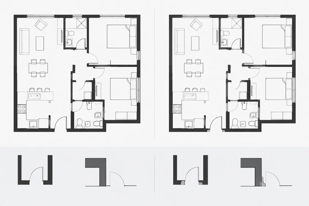
Pay particular attention to:
- Wall ends at doors and full-height openings
- Window recesses and changes in wall thickness
- Curved walls meeting straight segments
- Columns or structural walls embedded in partitions
- Shaft walls and multiple adjacent enclosures
- Exterior wall returns at entrances and storefronts
- Walls interrupted by expansion or separation joints
A hatch that leaks across rooms or refuses to recognize a region is a warning that the underlying boundary may be incomplete. Increasing gap tolerance or drawing an arbitrary patch can conceal the immediate symptom, but it may leave unreliable plan geometry in place.
Separate Wall Linework from Poche
Place poche on a dedicated layer rather than combining it with wall outlines. Separation makes it easier to control color, screening, plotting, visibility, and draw order without changing the wall geometry.
A practical layer structure may distinguish among:
- Wall outlines or primary wall linework
- General cut-wall poche
- Material-specific hatches
- Existing construction graphics
- New construction graphics
- Demolition graphics
- Structural elements shown in the architectural background
Layer names should follow the project’s established naming framework. The important point is functional separation, not a universal layer name. Keep hatch color and other object properties set according to the office’s layer-based or plot-style workflow unless a documented exception is necessary.
Create Maintainable Poche Boundaries
There are two common ways to define wall poche: selecting existing wall boundaries or creating separate closed boundary objects. Each method has advantages.
Using Existing Wall Geometry
Referencing clean wall linework can reduce duplicate geometry. It works well when walls are stable and openings are accurately drafted. Associative hatches can update when their recognized boundaries change, but they still require review after significant edits.
Using Separate Closed Boundaries
Closed polylines can provide deliberate control in complicated wall assemblies or imported drawings. They can also make boundary troubleshooting easier. However, they introduce another set of objects that must remain coordinated with the wall linework.
If separate boundaries are used, place them on a controlled nonplotting or construction layer when appropriate to the office workflow. Avoid leaving visible duplicate outlines around the hatch, since they can unintentionally increase lineweight or create doubled geometry.
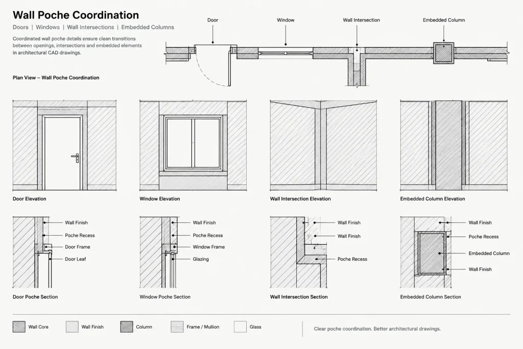
Coordinate Doors, Windows, and Openings
Poche should stop at genuine openings and continue through elements that remain cut by the plan plane. This sounds straightforward, but door frames, sidelights, recessed openings, and complex window profiles often create ambiguous hatch islands.
Review each opening type rather than assuming one hatch operation will resolve every condition. Confirm that:
- Door leaves remain visible against adjacent fills
- Frames and jambs are not buried by solid poche
- Glazed openings read differently from solid wall portions
- Full-height openings create a complete break in the wall mass
- Overhead items are not mistaken for cut geometry
- Casework and fixtures remain visually subordinate but legible
When an opening block includes masking objects, fills, or background geometry, test its interaction with the wall poche. Draw order can solve some display conflicts, but it should not become a substitute for correctly constructed boundaries.
Handle Existing, New, and Demolished Walls Deliberately
Renovation plans require more than a single wall fill. The graphic distinction among existing-to-remain, demolished, and new work should be defined by the project’s drawing conventions and applied consistently across plans, enlarged plans, sections, and legends.
Avoid relying on color alone because printed sheets may be monochrome and some readers may not perceive the intended color difference. Combine line type, lineweight, hatch, tone, and notation as appropriate. If demolition is shown on a separate plan, coordinate the remaining wall geometry with the new-work plan so that obsolete poche does not survive in later views.
When an existing wall is partially removed, divide the geometry at meaningful construction limits. A continuous hatch placed beneath demolition linework can misleadingly suggest that the entire wall remains.
Use Draw Order Carefully
Wall poche generally belongs behind wall outlines, symbols, tags, dimensions, and key annotations. Sending fills behind relevant linework helps preserve edges and opening details. However, global draw-order changes can produce unexpected results, especially when the plan contains blocks, external references, wipeouts, and multiple hatch layers.
Test representative conditions that include:
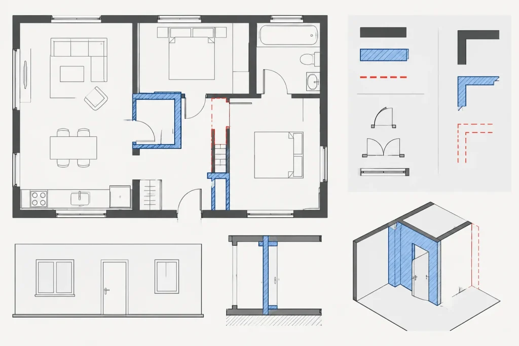
- A door in a poche wall
- A window with detailed frame linework
- A room tag near a narrow partition
- A column embedded in an exterior wall
- An xref containing its own fills or masks
- A viewport with layer overrides
If annotations need frequent masking to remain readable, the poche may be too visually heavy or the annotation placement may need adjustment.
Coordinate Poche Across Xrefs and Enlarged Plans
In a multi-file project, decide which file owns the poche. Common possibilities include the base floor-plan file, a dedicated annotation file, or the sheet-specific view file. Avoid placing overlapping wall fills in both a referenced model and its host sheet file unless there is a documented reason.
Enlarged plans often require more detailed wall geometry than the overall plan. Determine whether the enlarged view will use the same referenced poche, apply viewport-specific graphic control, or maintain a separate detail-level treatment. Whichever method is selected, changes to openings and wall thicknesses should be checked in both views.
Do not trace permanent poche over an xref without a clear update process. If the referenced walls move, the traced fill may remain behind and create subtle inaccuracies.
Quality-Control Checklist
Review wall poche in the plotted sheet context, not only in model space. A focused check should include the following:
- Confirm that every cut wall intended to receive poche is filled consistently.
- Look for hatch leaks into rooms, corridors, exterior space, and shafts.
- Check that doors, windows, and full-height openings remain readable.
- Verify that existing, new, and demolished construction are distinguishable.
- Inspect corners and wall junctions for white gaps or overlapping fills.
- Confirm that room tags, dimensions, section marks, and notes are not obscured.
- Compare overall and enlarged plans for mismatched openings or wall limits.
- Review xrefs for duplicate poche, conflicting masks, or inconsistent tones.
- Plot a PDF using the intended page setup and inspect it at normal viewing size.
- Recheck hatch boundaries after late wall, door, or window revisions.
Keep the Graphic Hierarchy Simple
Effective architectural wall poche makes the plan understandable at a glance. The cut building elements form the primary figure, openings remain clear, and furniture, fixtures, dimensions, and annotations can be read without competing with the fill.
The most dependable workflow is to clean the wall geometry first, separate fill from outline layers, define a consistent renovation strategy, and test the result through the final plotting process. Poche should support the architectural information—not become another layer of geometry that the team struggles to maintain.
A Practical Decision Sequence
When wall poche becomes difficult to manage, troubleshoot the drawing in a deliberate order. Begin with the architectural geometry, then review the hatch boundary, layer properties, draw order, referenced content, and plotted output. This sequence helps distinguish a drafting problem from a display or plotting problem.
- Geometry: Confirm that wall faces, returns, intersections, and opening limits form intentional regions.
- Boundary behavior: Check whether the fill recognizes the correct outer edge and internal islands.
- Layer control: Verify that poche is separated from outlines and assigned the intended visibility and plotting behavior.
- Object interaction: Inspect doors, windows, blocks, masks, annotations, and structural elements for conflicts.
- File coordination: Identify whether the fill belongs in the base drawing, an annotation file, or a sheet-specific file.
- Output: Review the result through the actual page setup, viewport, plot style, and PDF workflow.
Editing Without Creating Graphic Debt
Wall revisions should include a poche review as part of the drafting task. Moving a wall, changing an opening, or replacing a referenced plan can leave fills that appear acceptable at first glance but no longer match the current geometry. These remnants are especially difficult to notice where screened fills, masks, and dense linework overlap.
A maintainable file makes the relationship between wall outlines and poche easy for another drafter to understand. Dedicated layers, predictable ownership, limited boundary duplication, and consistent graphic conventions reduce the need for local patches. If a special condition requires a manual exception, keep it isolated and recognizable rather than embedding it in unrelated linework.
What to Check After a Revision
- Review the ends of every wall affected by a moved or resized opening.
- Inspect intersections connected to revised wall segments.
- Confirm that hatch islands still represent actual voids.
- Look for old fills beneath demolition graphics or masking objects.
- Compare the base plan with enlarged or sheet-specific views.
- Regenerate the plotted output and inspect graphic hierarchy at the intended viewing condition.
The goal is not simply to produce a closed hatch region. The goal is a coordinated plan in which cut elements read clearly, openings remain accurate, and future edits can be completed without rebuilding the graphic treatment.
Frequently Asked Questions
Is wall poche the same as a material hatch?
No. Wall poche primarily establishes the visual mass of elements cut by the plan. A material hatch identifies or suggests construction material. A drawing may combine these functions, but the legend, notes, wall types, and details should make the intended meaning clear.
Should wall poche be associative?
Associative behavior can make routine edits easier when the recognized boundaries are clean and stable. It does not remove the need for review. Significant changes to walls, openings, blocks, or referenced geometry can still produce incorrect boundaries or unexpected islands.
Why does a wall hatch leak into an adjacent room?
A leak usually indicates an incomplete boundary, a small gap, an unintended overlap, or geometry that does not meet as expected. Inspect the relevant wall faces and opening limits before relying on tolerance changes or temporary patches.
Should poche be placed in the base plan or the sheet file?
Either location can work if file ownership is clearly defined. The best choice depends on how the project shares model geometry, annotations, enlarged views, and sheet-specific graphics. Avoid duplicate fills in both locations unless the workflow intentionally requires them.
How should poche interact with doors and windows?
The fill should stop where a genuine opening interrupts the cut wall while preserving readable frames, jambs, leaves, glazing, and adjacent linework. Complex opening blocks should be tested for masks, internal fills, and draw-order conflicts.
Why does poche look clear on screen but too heavy in a PDF?
Screen display does not fully represent plot styles, screening, lineweight relationships, viewport settings, or PDF processing. Evaluate representative plan areas through the same output workflow intended for the finished sheets.