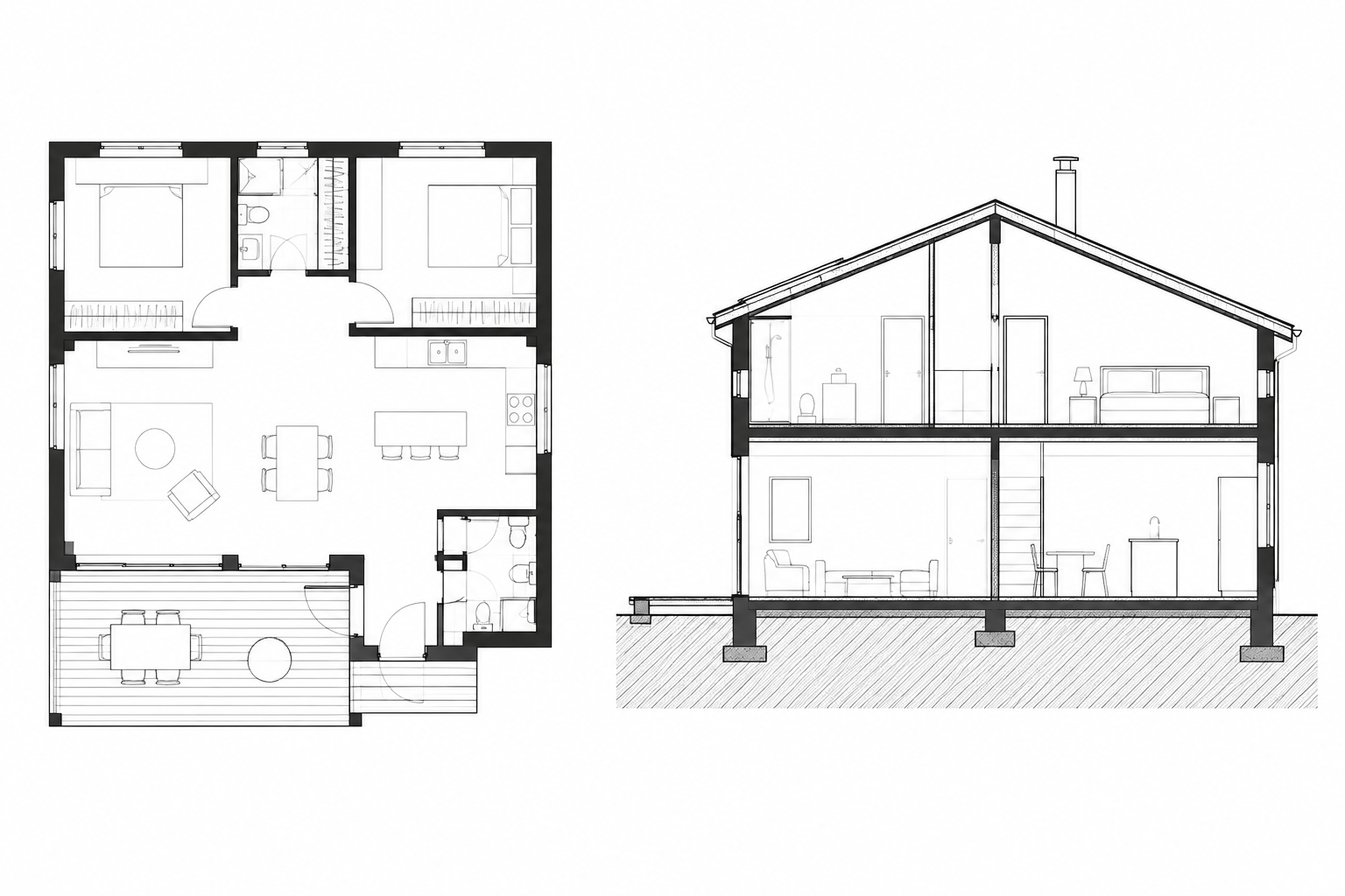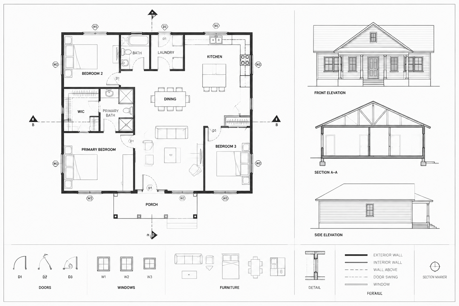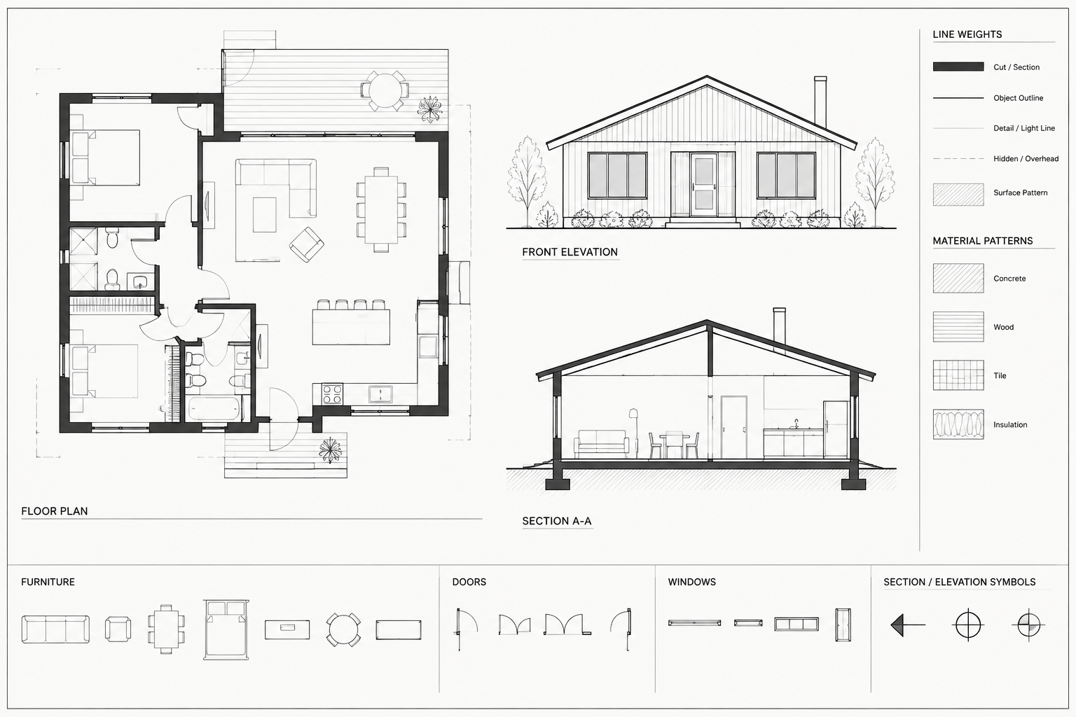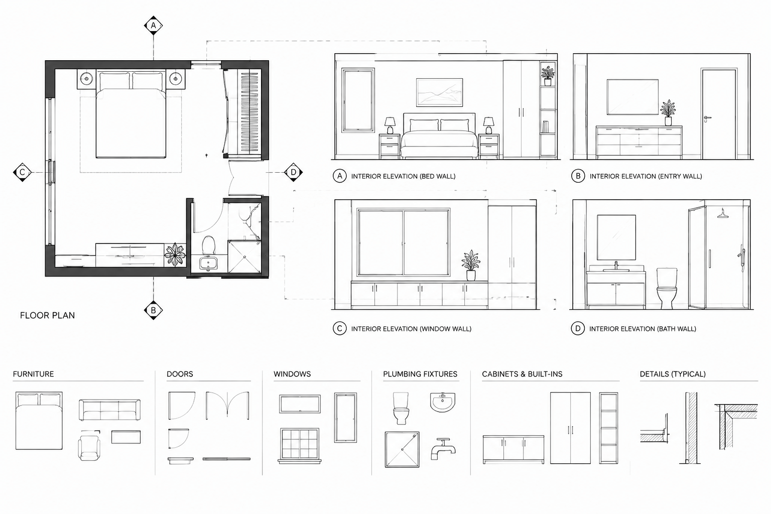
Interior elevations show the vertical surfaces of a room as if the viewer were looking directly at each wall. They communicate information that may be difficult to understand from a floor plan alone, including cabinet arrangements, wall finishes, fixture mounting relationships, openings, trim, shelving, and changes in ceiling form.
A reliable interior elevation begins with coordinated project geometry rather than isolated drafting. The floor plan establishes the room boundaries and horizontal locations, while sections, reflected ceiling plans, schedules, and design information help define vertical conditions. The goal is not simply to produce an attractive view. It is to create a drawing that remains consistent with the rest of the document set.
What an Interior Elevation Should Communicate
The required content varies with the room and project phase. A kitchen elevation may emphasize casework, appliances, counters, and backsplashes. A restroom elevation may focus on plumbing fixtures, accessories, mirrors, partitions, and finish transitions. An office elevation may show glazing, wall-mounted equipment, built-in storage, and power or data coordination.
Common interior elevation content includes:
- Walls, floors, ceilings, soffits, and other major room boundaries
- Doors, windows, borrowed lights, and interior glazing
- Cabinets, counters, shelving, niches, and built-in furniture
- Plumbing fixtures, appliances, equipment, and accessories
- Wall finish boundaries and material changes
- Reference levels, dimensions, labels, and keyed notes
- Links to schedules, details, or related drawing views
Only include information that is supported by the project documents. Generic CAD blocks can assist with graphic layout, but their sizes, mounting positions, clearances, and configurations must be checked against selected products, design requirements, and applicable regulations.
Prepare the Floor Plan Before Projecting the View
Start with a dependable floor plan. Confirm that walls connect correctly, openings are current, room names are established, and fixed equipment is placed intentionally. Resolve obvious conflicts before projecting them into another view.
Identify which wall or walls require elevations. Highly repetitive or visually simple walls may not need the same level of documentation as walls containing casework, equipment, finish patterns, or complex openings. The drawing set should explain the room without creating unnecessary duplicate views.
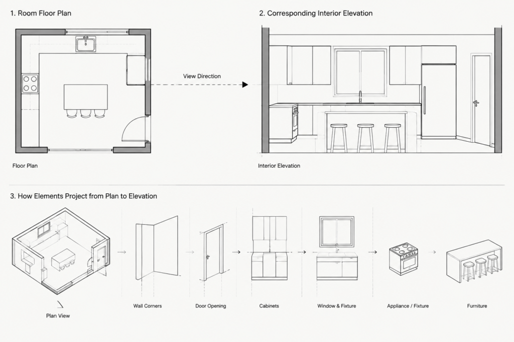
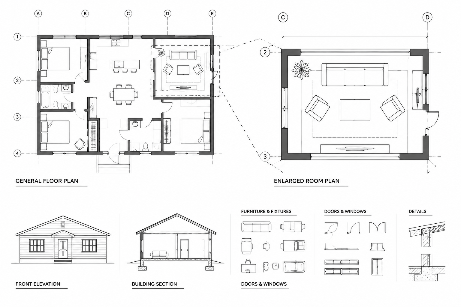
Place an interior elevation marker in the plan and give each view a stable identifier. The marker should clearly show the viewing direction. If several walls are documented with one room marker, make the relationship between each arrow and each elevation unmistakable.
Establish a Controlled CAD Workspace
Create the elevation in a deliberate drawing location rather than in an arbitrary open area of model space. Keep enough separation between views to avoid overlapping notes and dimensions, but organize related room elevations as a recognizable group.
Use layers that distinguish the primary drawing components. A practical organization may separate:
- Major profile and cut-adjacent edges
- Visible object outlines
- Secondary surface lines and joints
- Overhead or concealed information, when necessary
- Dimensions, text, tags, and reference symbols
- Finish patterns or material indications
- Equipment and fixture graphics
Layer names and plotting behavior should follow the project CAD standard. Avoid creating a special layer for every individual object unless that degree of control serves a real coordination or display purpose.
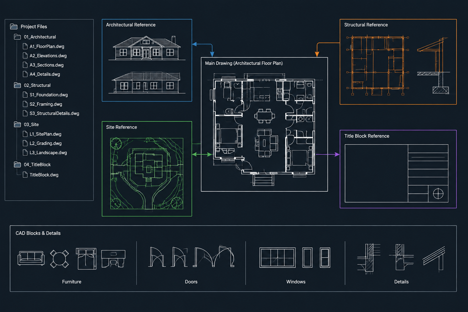
Project the Main Geometry from the Plan
Orient the elevation so the selected wall reads straight on. Use construction lines or temporary projection geometry to transfer the horizontal locations of wall returns, doors, windows, cabinets, fixtures, and equipment from the plan.
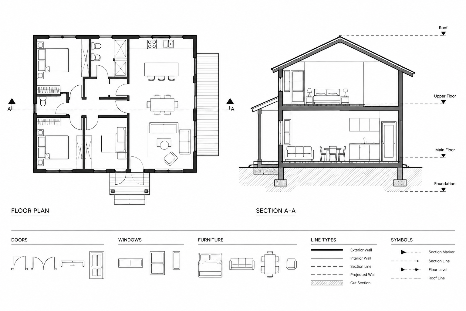
Horizontal projection establishes where elements appear across the wall, but it does not determine their vertical placement. Heights and levels must come from coordinated design information such as building sections, room sections, ceiling plans, schedules, product information, or project-specific details.
A useful drafting sequence is:
- Draw the floor or base reference.
- Establish the ceiling, soffit, or upper room boundary.
- Project wall ends, corners, and major openings.
- Add built-in casework and fixed equipment.
- Add fixtures, accessories, trim, and finish divisions.
- Remove temporary construction geometry.
- Apply line hierarchy before annotation.
Do not assume that every object visible in plan should appear in elevation. A direct wall elevation normally emphasizes the viewed surface and objects associated with it. Elements in front of the wall may be included selectively when they are needed to explain the design, but too much foreground information can obscure the wall itself.
Build the View from Large Forms to Small Details
Room boundaries and openings
Begin with the main architectural envelope. Show the floor line, ceiling relationship, wall returns, and openings. Coordinate door and window locations with the plan and schedules. If an opening has trim, a sill, a head condition, or adjacent finish work, represent only the level of detail appropriate to the drawing scale.
Casework and built-ins
Draft cabinets as coordinated assemblies rather than collections of unrelated rectangles. Align base units, wall units, tall units, countertops, fillers, panels, and open shelving with the plan. Indicate door and drawer divisions where they are needed for design or fabrication coordination, but avoid implying construction details that have not been developed.
Fixtures, equipment, and accessories
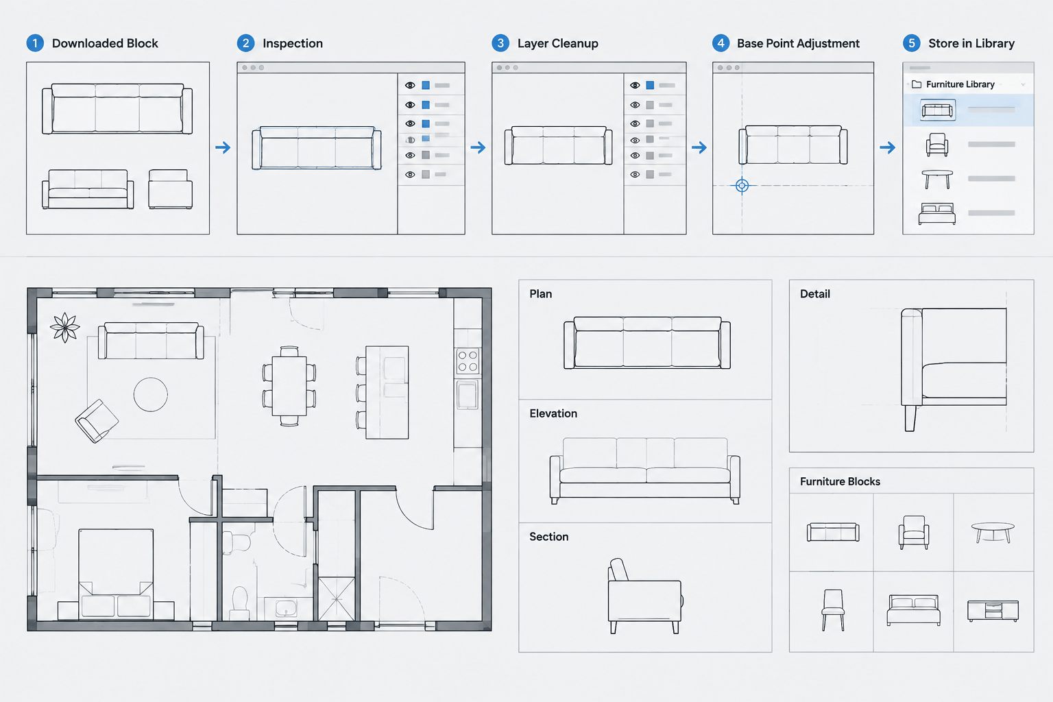
Use elevation-view blocks when available. A plan symbol rotated into a vertical orientation is rarely an adequate substitute because the two views communicate different geometry. Check each block for scale, insertion point, graphic density, and consistency with the selected object.
Finishes and surface patterns
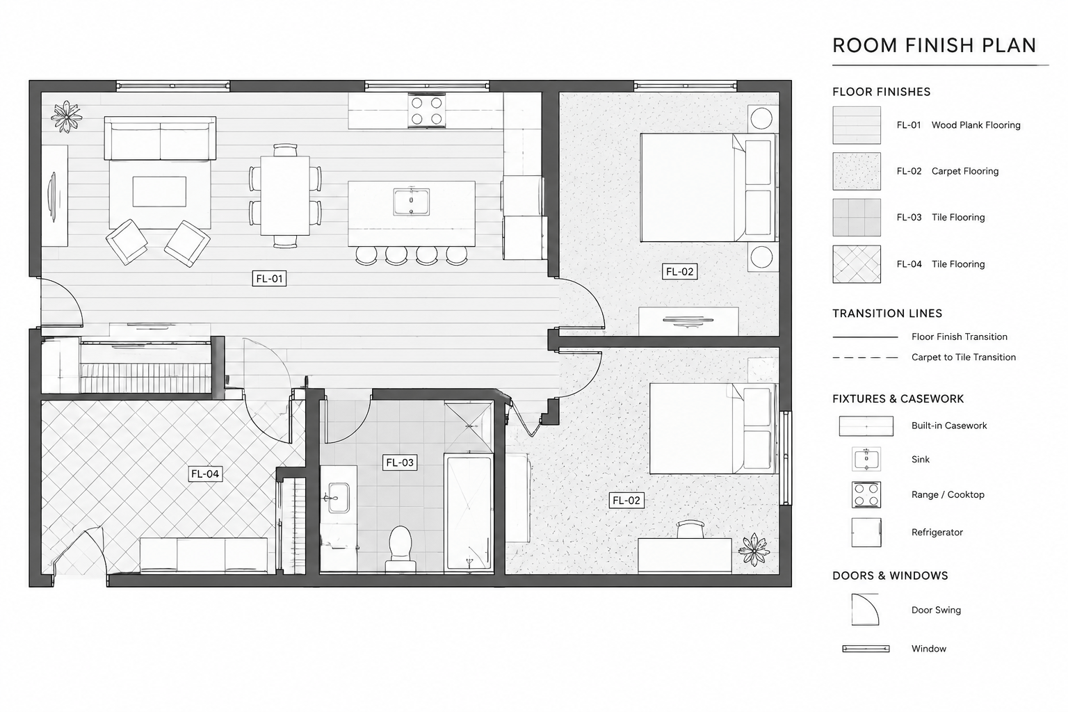
Show finish transitions when their locations matter. Tile extents, wall panels, mirrors, backsplashes, feature surfaces, and changes in paint or cladding can be outlined and labeled. Patterns should remain subordinate to object outlines and annotation. Dense hatching can make a view difficult to read and may perform poorly when printed or exported.
Use Line Hierarchy to Create Depth
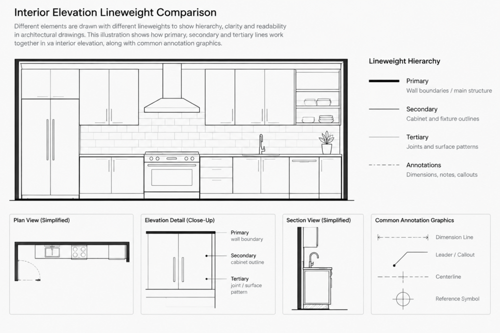
An interior elevation is a flattened view, so line hierarchy must explain which elements are dominant. The perimeter of the viewed wall, major openings, and prominent built-ins generally need stronger graphic emphasis than joints, seams, hardware, or finish patterns.
| Graphic category | Typical content | Drafting purpose |
|---|---|---|
| Primary | Major boundaries, wall returns, openings, prominent built-ins | Defines the overall form and limits of the view |
| Secondary | Cabinet edges, fixture outlines, trim, panels | Explains components attached to or placed against the wall |
| Tertiary | Joints, hardware, surface patterns, minor seams | Adds supporting information without dominating the drawing |
| Annotation | Dimensions, notes, tags, levels, references | Communicates information that geometry alone cannot show |
Always review the plotted result. A hierarchy that looks clear on a bright monitor may become too heavy, too faint, or visually compressed on the sheet.
Dimension and Annotate with a Clear Purpose
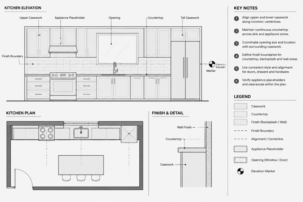
Dimensions should support construction, layout, and coordination rather than repeat every measurable line. Prioritize overall extents, controlling alignments, opening positions, critical heights, and relationships between fixed components.
Organize dimensions so their reference points are clear. Avoid dimensioning to hatch lines, loose decorative graphics, or block geometry that may change. Where possible, reference stable architectural elements such as wall faces, centerlines, finished surfaces, cabinet edges, or opening limits, according to the project convention.
Use notes for material identity, finish boundaries, equipment references, and conditions that cannot be communicated efficiently through dimensions. Keep note language consistent across related elevations. If an item is controlled by a schedule or specification, reference that source instead of filling the view with duplicated information that could become inconsistent.
Coordinate the Elevation with Other Drawings
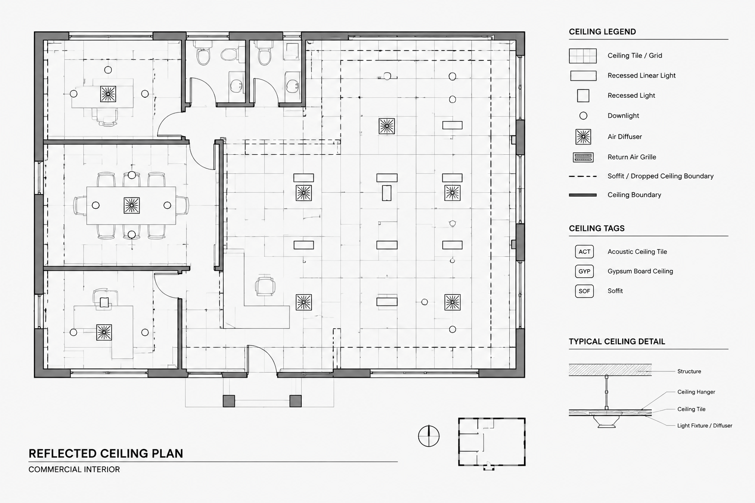
Interior elevations should be checked against more than the floor plan. Compare the view with the reflected ceiling plan for ceiling changes, lights, diffusers, and soffits that affect the wall composition. Review building sections for floor and ceiling relationships. Check door, window, finish, equipment, and casework information where those documents are part of the project.
Coordination is especially important when several drawing types describe the same object. For example, a cabinet may appear in plan, elevation, section, schedule, and detail. Decide which view controls each type of information, and avoid creating contradictory dimensions or labels.
Common Interior Elevation Drafting Problems
- Drawing from memory: Project locations from coordinated geometry instead of estimating them visually.
- Overusing downloaded blocks: Generic blocks can suggest the wrong size, configuration, or mounting relationship.
- Showing too much depth: Excess foreground content can make the wall elevation difficult to interpret.
- Using one lineweight for everything: Equal emphasis flattens the view and hides the main architectural form.
- Duplicating uncontrolled notes: Repeated information can drift out of coordination as the design changes.
- Ignoring sheet scale: Tiny seams, hardware, and hatch patterns may merge or disappear when plotted.
- Leaving projection lines in the file: Temporary geometry can plot accidentally or confuse later editing.
Final Quality-Control Checklist
- Confirm that the elevation marker points toward the correct wall.
- Compare wall lengths, returns, openings, and fixed objects with the floor plan.
- Verify vertical information against coordinated project sources.
- Check that blocks represent the intended view and are not unverified placeholders.
- Review casework divisions, countertop edges, fillers, and adjacent clearances.
- Confirm that finish boundaries match the notes and related finish information.
- Remove duplicate lines, temporary projections, and hidden stray objects.
- Check text size, dimension readability, line hierarchy, and hatch density on the sheet.
- Verify that view titles and references lead to the correct drawing locations.
A strong interior elevation is selective, coordinated, and easy to revise. By projecting dependable plan geometry, sourcing vertical conditions from verified project information, and applying disciplined linework and annotation, CAD users can produce views that add real value to an architectural drawing set.